2012 NISSAN 370Z COUPE display
[x] Cancel search: displayPage 7 of 427
Illustrated table of contents0
Safety — Seats, seat belts and supplemental
restraint system1
Instruments and controls
Pre-driving checks and adjustments
Center display, heater, air conditioner, audio, phone
and voice recognition systems
Starting and driving
In case of emergency
Appearance and care
Maintenance and do-it-yourself
Technical and consumer information
Index
2
3
4
5
6
7
8
9
10
Table of
Contents
Page 19 of 427
SSI0653
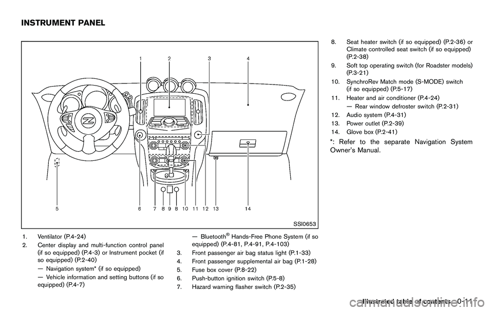
1. Ventilator (P.4-24)
2. Center display and multi-function control panel(if so equipped) (P.4-3) or Instrument pocket (if
so equipped) (P.2-40)
— Navigation system* (if so equipped)
— Vehicle information and setting buttons (if so
equipped) (P.4-7) — Bluetooth®Hands-Free Phone System (if so
equipped) (P.4-81, P.4-91, P.4-103)
3. Front passenger air bag status light (P.1-33)
4. Front passenger supplemental air bag (P.1-28)
5. Fuse box cover (P.8-22)
6. Push-button ignition switch (P.5-8)
7. Hazard warning flasher switch (P.2-35) 8. Seat heater switch (if so equipped) (P.2-36) or
Climate controlled seat switch (if so equipped)
(P.2-38)
9. Soft top operating switch (for Roadster models) (P.3-21)
10. SynchroRev Match mode (S-MODE) switch (if so equipped) (P.5-17)
11. Heater and air conditioner (P.4-24) — Rear window defroster switch (P.2-31)
12. Audio system (P.4-31)
13. Power outlet (P.2-39)
14. Glove box (P.2-41)
*: Refer to the separate Navigation System
Owner’s Manual.
Illustrated table of contents0-11
INSTRUMENT PANEL
Page 20 of 427
0-12Illustrated table of contents
SSI0509
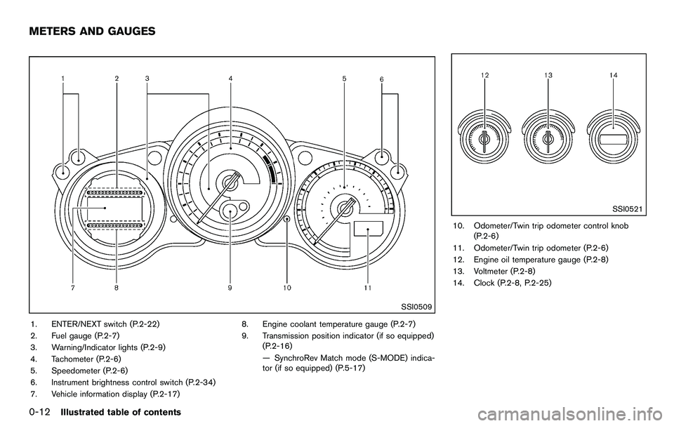
1. ENTER/NEXT switch (P.2-22)
2. Fuel gauge (P.2-7)
3. Warning/Indicator lights (P.2-9)
4. Tachometer (P.2-6)
5. Speedometer (P.2-6)
6. Instrument brightness control switch (P.2-34)
7. Vehicle information display (P.2-17)8. Engine coolant temperature gauge (P.2-7)
9. Transmission position indicator (if so equipped)
(P.2-16)
— SynchroRev Match mode (S-MODE) indica-
tor (if so equipped) (P.5-17)
SSI0521
10. Odometer/Twin trip odometer control knob(P.2-6)
11. Odometer/Twin trip odometer (P.2-6)
12. Engine oil temperature gauge (P.2-8)
13. Voltmeter (P.2-8)
14. Clock (P.2-8, P.2-25)
METERS AND GAUGES
Page 63 of 427
SPA1097
SUPPLEMENTAL AIR BAG WARNING
LIGHT
The supplemental air bag warning light, display-
ing
in the instrument panel, monitors the
circuits of the supplemental front-impact air bag,
front seat-mounted side-impact supplemental
air bag, roof-mounted (Coupe models) or door-
mounted (Roadster models) curtain side-impact
supplemental air bag, and seat belt pretensioner
systems. The monitored circuits include the air
bag systems, pretensioners and all related
wiring.
When the ignition switch is in the ON position,
the supplemental air bag warning light illumi-
nates for about 7 seconds and then turns off. This means the system is operational.
If any of the following conditions occur, the front
air bag, side air bag, curtain air bag and
pretensioner systems need servicing:
.
The supplemental air bag warning light
remains on approximately 7 seconds after
the ignition switch is pushed to the ON
position.
. The supplemental air bag warning light
flashes intermittently.
. The supplemental air bag warning light does
not come on at all.
Under these conditions, the front air bag, side air
bag, curtain air bag or pretensioner systems may
not operate properly. They must be checked and
repaired. Take your vehicle to the nearest
NISSAN dealer.
WARNING
If the supplemental air bag warning
light is on, it could mean that the front
air bag, side air bag, curtain air bag
and/or pretensioner systems will not
operate in an accident. To help avoid
injury to yourself or others, have your
vehicle checked by a NISSAN dealer as
soon as possible.
REPAIR AND REPLACEMENT PRO-
CEDURE
The front air bags, side air bags, curtain air bags
and pretensioners are designed to activate on a
one-time-only basis. As a reminder, unless it is
damaged, the supplemental air bag warning light
will remain illuminated after inflation has oc-
curred. Repair and replacement of these sys-
tems should be done only by a NISSAN dealer.
When maintenance work is required on the
vehicle, the front air bags, side air bags, curtain
air bags, pretensioners and related parts should
be pointed out to the person conducting the
maintenance. The ignition switch should always
be in the LOCK position when working under
the hood or inside the vehicle.
WARNING
. Once a front air bag, side air bag, or
curtain air bag has inflated, the air
bag module will not function again
and must be replaced. Additionally,
the activated pretensioner must
also be replaced. The air bag mod-
ule and pretensioner system should
be replaced by a NISSAN dealer.
The air bag module and preten-
sioner system cannot be repaired.
Safety — Seats, seat belts and supplemental restraint system1-41
Page 65 of 427
2 Instruments and controls
Cockpit ........................................................................\
................ 2-3
Instrument panel ........................................................................\
2-4
Meters and gauges ................................................................... 2-5
Speedometer and odometer ............................................ 2-6
Tachometer ........................................................................\
... 2-6
Engine coolant temperature gauge ................................ 2-7
Fuel gauge ........................................................................\
.... 2-7
Triple meter ........................................................................\
... 2-8
Warning/indicator lights and audible reminders ............... 2-9 Checking bulbs ................................................................. 2-10
Warning lights ................................................................... 2-10
Indicator lights ................................................................... 2-14
Audible reminders ............................................................ 2-16
Vehicle information display .................................................. 2-17 Operational indicators ..................................................... 2-18
Warnings and alerts ........................................................ 2-20
Maintenance indicators ................................................... 2-21
Trip computer .................................................................... 2-22
Security systems .................................................................... 2-27 Vehicle Security System ................................................. 2-27
NISSAN Vehicle Immobilizer System .......................... 2-28
Windshield wiper and washer switch ............................... 2-29
Rear window defroster switch ............................................ 2-31
Headlight and turn signal switch ....................................... 2-31 Xenon headlights .............................................................. 2-31 Headlight switch ............................................................ 2-32
Turn signal switch .......................................................... 2-35
Fog light switch (if so equipped) .............................. 2-35
Hazard warning flasher switch ........................................... 2-35
Horn ........................................................................\
.................. 2-36
Heated seats (if so equipped) ........................................... 2-36
Climate controlled seats (if so equipped) ...................... 2-38
Vehicle Dynamic Control (VDC) OFF switch ................. 2-39
Power outlet ........................................................................\
.... 2-39
Storage ........................................................................\
............ 2-40
Instrument pocket (except for navigation system
equipped models) .......................................................... 2-40
Cup holders ..................................................................... 2-40
Glove box ........................................................................\
. 2-41
Console box .................................................................... 2-42
Rear parcel box .............................................................. 2-42
Cargo cover (if so equipped) ..................................... 2-43
Windows ........................................................................\
......... 2-44 Power windows .............................................................. 2-44
Interior lights ........................................................................\
... 2-46
Map lights ........................................................................\
2-46
Interior light control switch .......................................... 2-47
Vanity mirror lights ................................................................. 2-48
Cargo area courtesy light (Roadster models) ............... 2-48
Cargo light (Coupe models) .............................................. 2-48>
Page 68 of 427
2-4Instruments and controls
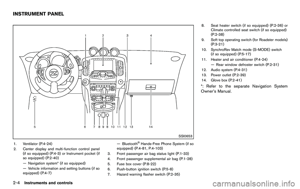
SSI0653
1. Ventilator (P.4-24)
2. Center display and multi-function control panel(if so equipped) (P.4-3) or Instrument pocket (if
so equipped) (P.2-40)
— Navigation system* (if so equipped)
— Vehicle information and setting buttons (if so
equipped) (P.4-7) — Bluetooth®Hands-Free Phone System (if so
equipped) (P.4-81, P.4-103)
3. Front passenger air bag status light (P.1-33)
4. Front passenger supplemental air bag (P.1-28)
5. Fuse box cover (P.8-22)
6. Push-button ignition switch (P.5-8)
7. Hazard warning flasher switch (P.2-35) 8. Seat heater switch (if so equipped) (P.2-36) or
Climate controlled seat switch (if so equipped)
(P.2-38)
9. Soft top operating switch (for Roadster models) (P.3-21)
10. SynchroRev Match mode (S-MODE) switch (if so equipped) (P.5-17)
11. Heater and air conditioner (P.4-24) — Rear window defroster switch (P.2-31)
12. Audio system (P.4-31)
13. Power outlet (P.2-39)
14. Glove box (P.2-41)
*: Refer to the separate Navigation System
Owner’s Manual.
INSTRUMENT PANEL
Page 69 of 427
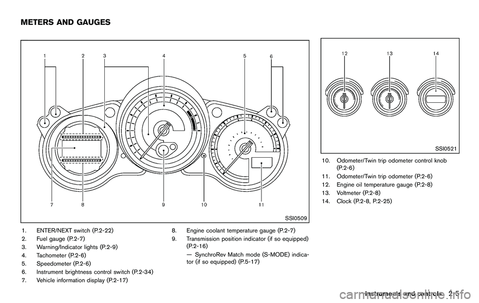
SSI0509
1. ENTER/NEXT switch (P.2-22)
2. Fuel gauge (P.2-7)
3. Warning/Indicator lights (P.2-9)
4. Tachometer (P.2-6)
5. Speedometer (P.2-6)
6. Instrument brightness control switch (P.2-34)
7. Vehicle information display (P.2-17)8. Engine coolant temperature gauge (P.2-7)
9. Transmission position indicator (if so equipped)
(P.2-16)
— SynchroRev Match mode (S-MODE) indica-
tor (if so equipped) (P.5-17)
SSI0521
10. Odometer/Twin trip odometer control knob(P.2-6)
11. Odometer/Twin trip odometer (P.2-6)
12. Engine oil temperature gauge (P.2-8)
13. Voltmeter (P.2-8)
14. Clock (P.2-8, P.2-25)
Instruments and controls2-5
METERS AND GAUGES
Page 70 of 427
2-6Instruments and controls
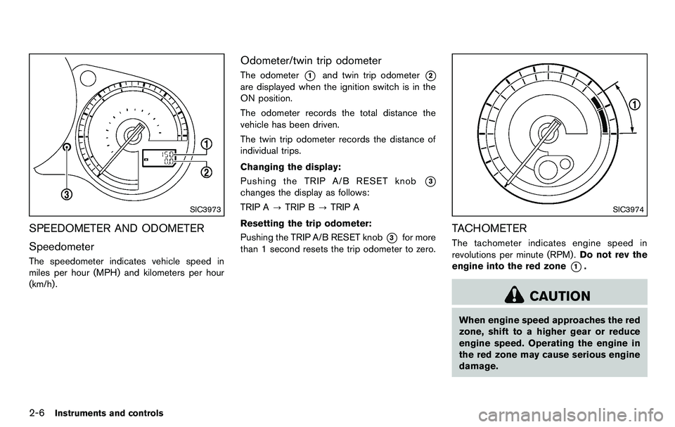
SIC3973
SPEEDOMETER AND ODOMETER
Speedometer
The speedometer indicates vehicle speed in
miles per hour (MPH) and kilometers per hour
(km/h) .
Odometer/twin trip odometer
The odometer*1and twin trip odometer*2
are displayed when the ignition switch is in the
ON position.
The odometer records the total distance the
vehicle has been driven.
The twin trip odometer records the distance of
individual trips.
Changing the display:
Pushing the TRIP A/B RESET knob
*3
changes the display as follows:
TRIP A?TRIP B ?TRIP A
Resetting the trip odometer:
Pushing the TRIP A/B RESET knob
*3for more
than 1 second resets the trip odometer to zero.
SIC3974
TACHOMETER
The tachometer indicates engine speed in
revolutions per minute (RPM) . Do not rev the
engine into the red zone
*1.
CAUTION
When engine speed approaches the red
zone, shift to a higher gear or reduce
engine speed. Operating the engine in
the red zone may cause serious engine
damage.