Page 643 of 714
7-42 Vehicle care and maintenance
7
Engine compartmentIn the engine compartment, the fuse block is located as shown
in the illustration.Fuse load capacities
N00954800169
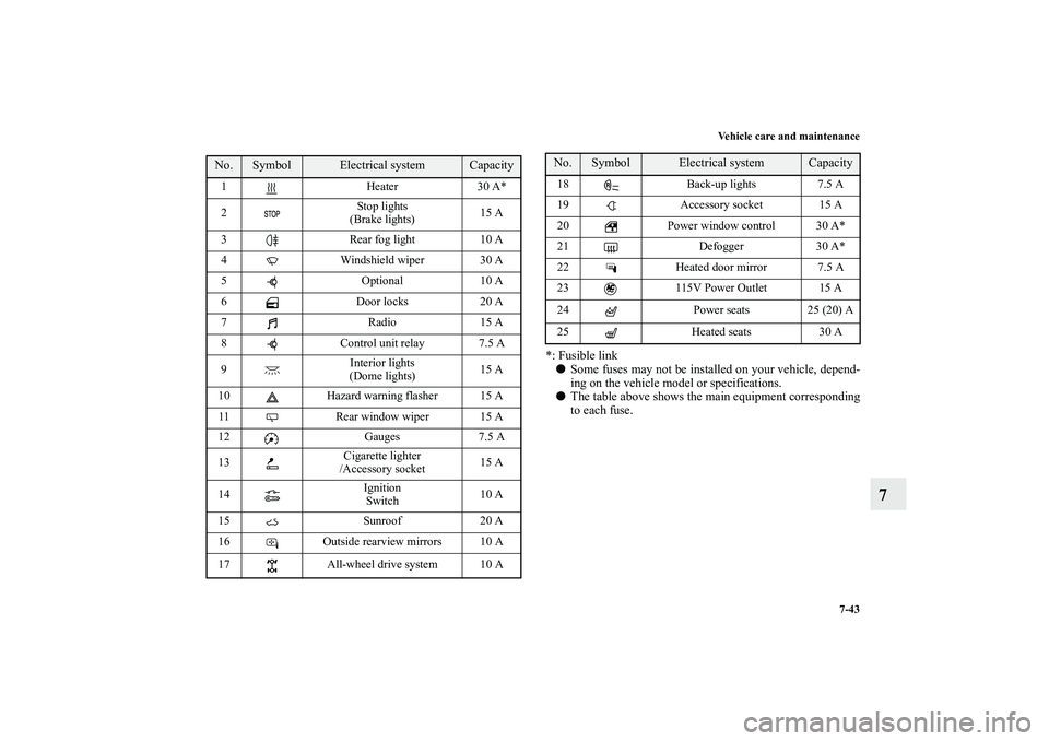
This fuse list shows the names of the electrical systems and
their fuse capacities.
There are spare fuses in the fuse block cover in the engine
compartment. Always replace a blown fuse with one of the
same capacity as the original.
Passenger compartment fuse location table
1- Push the lock lever.
2- Remove the fuse block cover.
Passenger compartment fuse location
Sub fuse block Main fuse block
BK0138000US.book 42 ページ 2011年4月13日 水曜日 午前11時17分
Page 644 of 714
Vehicle care and maintenance
7-43
7
*: Fusible link
�Some fuses may not be installed on your vehicle, depend-
ing on the vehicle model or specifications.
�The table above shows the main equipment corresponding
to each fuse.
No.
Symbol
Electrical system
Capacity
1 Heater 30 A*
2Stop lights
(Brake lights)15 A
3 Rear fog light 10 A
4 Windshield wiper 30 A
5 Optional 10 A
6 Door locks 20 A
7Radio15 A
8 Control unit relay 7.5 A
9Interior lights
(Dome lights)15 A
10 Hazard warning flasher 15 A
11 Rear window wiper 15 A
12 Gauges 7.5 A
13Cigarette lighter
/Accessory socket15 A
14Ignition
Switch10 A
15 Sunroof 20 A
16 Outside rearview mirrors 10 A
17 All-wheel drive system 10 A
18 Back-up lights 7.5 A
19 Accessory socket 15 A
20 Power window control 30 A*
21 Defogger 30 A*
22 Heated door mirror 7.5 A
23 115V Power Outlet 15 A
24 Power seats 25 (20) A
25 Heated seats 30 ANo.
Symbol
Electrical system
Capacity
BK0138000US.book 43 ページ 2011年4月13日 水曜日 午前11時17分
Page 645 of 714
7-44 Vehicle care and maintenance
7
Engine compartment fuse location tableEngine compartment fuse location
Behind the fuse block cover
No.
Symbol
Electrical system
Capacity
1 Front fog lights 15 A
2 Engine 7.5 A
3 Automatic transaxle 20 A
4Horn10 A
5 Alternator 7.5 A
6 Headlight washer 20 A
7 Air conditioning 10 A
8ETV/Oil cooler fan
(Twin Clutch SST)15 A
9 Security horn 20 A
10 Wiper deicer 15 A
11 — — —
12 Power gate 30 A
13 Daytime running lights 10 A
14Headlight
(high beam) (left)10 A
15Headlight
(high beam) (right)10 A
16Headlight
(low beam)
(left)Discharge 20 A
BK0138000US.book 44 ページ 2011年4月13日 水曜日 午前11時17分
Page 646 of 714

Vehicle care and maintenance
7-45
7
*: Fusible link
�Some fuses may not be installed on your vehicle, depend-
ing on the vehicle model or specifications.
�The table above shows the main equipment corresponding
to each fuse.
There are no 7.5 A, 25 A or 30 A spare fuses. If a fuse of one of
these capacities blows, replace it temporarily by borrowing one
of the fuses indicated below.
7.5 A: 10 A spare fuse
25 A: 20 A spare fuse
30 A: 30 A audio amplifier fuse
Replace the borrowed fuse with a fuse that has the correct
capacity as soon as possible.
17Headlight
(low beam)
(right)Discharge 20 A
18Headlight
(low beam)
(left)Halogen 10 A
19Headlight
(low beam)
(right)Halogen 10 A
20 ENG/POWER 10 A
21 Ignition coil 10 A
22ENG/POWER 20 A
Fuel line heater 25 A
23 Fuel pump 15 A
24 Starter 30 A*
25 — — —
26 Anti-lock braking system 40 A*
27 Anti-lock braking system 30 A*
28Air conditioning condenser fan
motor30 A*
29 Radiator fan 40 A*
30 IOD IOD 30 A
31 Audio amplifier 30 ANo.
Symbol
Electrical system
Capacity
32 Diesel 30 A
33 — Spare fuse 10 A
34 — Spare fuse 15 A
35 — Spare fuse 20 ANo.
Symbol
Electrical system
Capacity
BK0138000US.book 45 ページ 2011年4月13日 水曜日 午前11時17分
Page 647 of 714
7-46 Vehicle care and maintenance
7
Identification of fuse
Fuse replacement
N00954900014
1. Before replacing a fuse, always turn off the electrical item
connected to the fuse and turn the ignition switch to the
“LOCK” position.
2. There is a fuse remover (A) in the engine compartment
fuse block.
Capacity
Color
7.5 A Brown
10 A Red
15 A Blue
20 A Yellow
25 A Natural (white)
30 A Green (fuse type) /Pink (fusible link type)
40 A Green (fusible link type)
BK0138000US.book 46 ページ 2011年4月13日 水曜日 午前11時17分
Page 648 of 714
Vehicle care and maintenance
7-47
7
3. Clamp it on the fuse you wish to remove, and pull the fuse
straight out from the fuse block.4. Use the fuse location diagrams and the matching tables, to
check the fuse that is related to the problem. If the fuse is
not blown, something else must be causing the problem.
Have the system inspected by your authorized Mitsubishi
Motors dealer or a repair facility of your choice.
B- Fuse is OK
C- Blown fuse
BK0138000US.book 47 ページ 2011年4月13日 水曜日 午前11時17分
Page 654 of 714
Vehicle care and maintenance
7-53
7
2. Turn the bulb (B) counterclockwise to remove it. 3. While holding down the tab (C), pull out the socket (D).
4. To install the bulb, perform the removal steps in reverse.*- Front of the vehicle
BK0138000US.book 53 ページ 2011年4月13日 水曜日 午前11時17分
Page 655 of 714
7-54 Vehicle care and maintenance
7
Headlights (high beam, except for vehicles
equipped with high intensity discharge head-
lights)
N00901900034
1. Turn the cap (A) counterclockwise to remove it.
CAUTION
!�Handle halogen light bulb with care. The gas inside
a halogen light bulb is highly pressurized, so drop-
ping, knocking, or scratching a halogen light bulb
can cause it to shatter.�Never hold the halogen light bulb with a bare hand,
dirty glove, etc.
The oil from your hand could cause the bulb to
break the next time the headlights are used.
If the glass surface is dirty, clean it with alcohol and
let it dry completely before installing the bulb.
*- Front of the vehicle
BK0138000US.book 54 ページ 2011年4月13日 水曜日 午前11時17分


 counterclockwise to remove it. 3. While holding down the tab (C), pull out the socket (D).
4. To install the bulb, perform the removal steps in")

N00901900034
1. Turn the cap (A) counterclockwise to remove it.
CAU")