2012 MINI COUPE ROADSTER CONVERTIBLE check engine
[x] Cancel search: check enginePage 240 of 283
Replacing componentsMOBILITY
239
Adjusting the tire pressure
1.After driving approx. 3.1 miles/5 km or
10 minutes, stop at a suitable location.
2. Screw the connection hose 6 of the
compressor directly onto the tire valve.
3. Insert the plug 5 into the power socket in
the vehicle interior.
4. Adjust tire pressure to 1.8 bar/26 psi. With
the engine running:
> To increase the inflatio n pressure: switch on
the compressor. To check the current infla-
tion pressure, switch off the compressor.
Do not run the compressor for longer
than 10 minutes; otherwise, the
device will overheat and possibly be
damaged. <
> To decrease the inflation pressure: press the
release button 9.
If the tire cannot ma intain the inflation
pressure, drive the vehicle again, refer to
Distributing the sealan t. Then repeat steps
1to4.
If an inflation pressure of 1.8 bar/26 psi still
cannot be reached, then the tire is too heavily
damaged. Contact your nearest MINI dealer. <
Driving on
Do not exceed the permitted maximum
speed of 50 mph/80 km/h; doing so may
result in an accident. <
Replace the defective tire as soon as possible
and have the new wheel/tire assembly
balanced.
Have the Mobility Kit refilled.
Changing wheels
Run-flat tires
Tire change for run-flat tires:
> Prepare for tire change, page 240
> Jack up vehicle, page 241
> Tighten lug bolts, page 241
Space-saver spare tire
Tire change with space-saver spare tire:
>Remove the space-saver spare tire,
page 239
> Prepare for tire change, page 240
> Jack up vehicle, page 241
> Mount space-saver spare tire, page 241
> Tighten lug bolts, page 241
> Drive with space-saver spare tire, page 240
Removing the space-saver spare tire
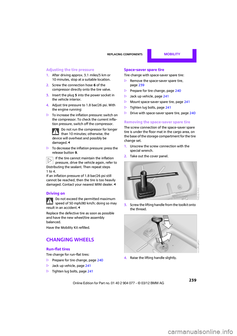
The screw connection of the space-saver spare
tire is under the floor mat in the cargo area, on
the base of the storage compartment for the tire
change set.
1. Unscrew the screw connection with the
special wrench.
2. Take out the cover panel.
3. Screw the lifting handle from the toolkit onto
the thread.
4. Raise the lifting handle slightly.
00320051004F004C00510048000300280047004C0057004C005200510003
Page 241 of 283
MOBILITYReplacing components
240
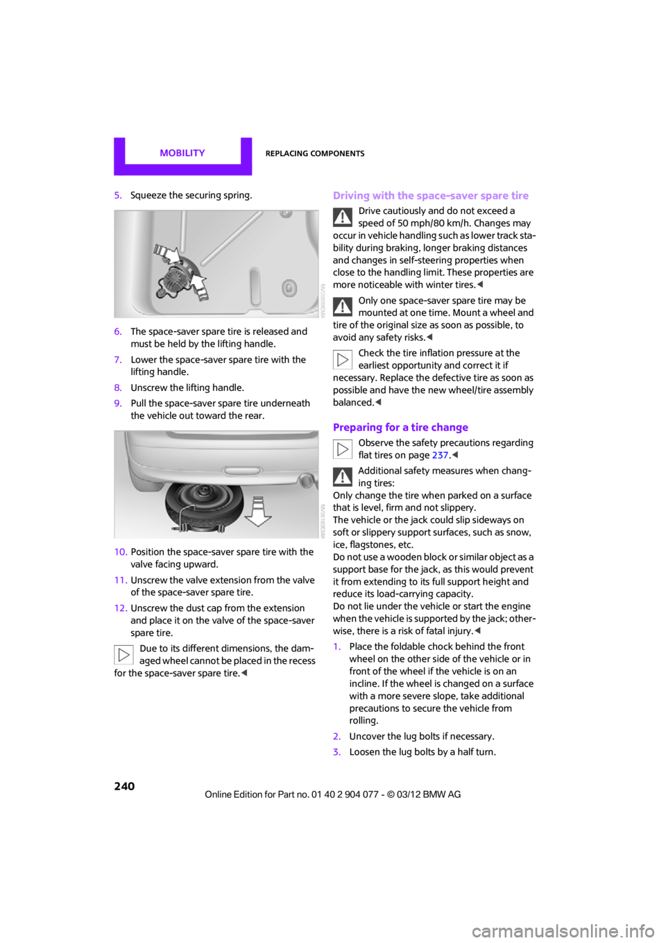
5.Squeeze the securing spring.
6. The space-saver spare tire is released and
must be held by the lifting handle.
7. Lower the space-saver spare tire with the
lifting handle.
8. Unscrew the lifting handle.
9. Pull the space-saver spare tire underneath
the vehicle out toward the rear.
10. Position the space-save r spare tire with the
valve facing upward.
11. Unscrew the valve extension from the valve
of the space-saver spare tire.
12. Unscrew the dust cap from the extension
and place it on the valve of the space-saver
spare tire.
Due to its different dimensions, the dam-
aged wheel cannot be placed in the recess
for the space-saver spare tire.
speed of 50 mph/80 km/h. Changes may
occur in vehicle handling such as lower track sta-
bility during braking, longer braking distances
and changes in self-steering properties when
close to the handling limit. These properties are
more noticeable with winter tires. <
Only one space-saver spare tire may be
mounted at one time. Mount a wheel and
tire of the original size as soon as possible, to
avoid any safety risks. <
Check the tire inflation pressure at the
earliest opportunity and correct it if
necessary. Replace the defe ctive tire as soon as
possible and have the ne w wheel/tire assembly
balanced. <
Preparing for a tire change
Observe the safety precautions regarding
flat tires on page 237.<
Additional safety measures when chang-
ing tires:
Only change the tire wh en parked on a surface
that is level, firm and not slippery.
The vehicle or the jack could slip sideways on
soft or slippery support surfaces, such as snow,
ice, flagstones, etc.
Do not use a wooden block or similar object as a
support base for the jack, as this would prevent
it from extending to its full support height and
reduce its load-carrying capacity.
Do not lie under the vehicle or start the engine
when the vehicle is supported by the jack; other-
wise, there is a risk of fatal injury. <
1. Place the foldable chock behind the front
wheel on the other side of the vehicle or in
front of the wheel if the vehicle is on an
incline. If the wheel is changed on a surface
with a more severe sl ope, take additional
precautions to secure the vehicle from
rolling.
2. Uncover the lug bolts if necessary.
3. Loosen the lug bolts by a half turn.
00320051004F004C00510048000300280047004C0057004C005200510003
Page 243 of 283

MOBILITYReplacing components
242
Starting-aid terminals
Only charge the battery in the vehicle when the
engine is off. Connections, refer to Jump-start-
ing on page 243.
Charger
The use of a charger ensures that the battery has
a sufficient charge even when it is used for fre-
quent short-distance driv es, for example. Charg-
ers that have been developed especially for the
vehicle and adapted to the vehicle electrical
system are available at your MINI dealer.
Disposal
After replacing old batteries, return the
used batteries to your MINI dealer or to a
recycling center. Maintain the battery in an
upright position for transport and storage.
Always secure the battery against tipping over
during transport. <
Power failure
After a temporary power loss, some equipment
may not be fully functional and may require
initialization. Individual se ttings are also lost and
must be reprogrammed:
> Time and date
These values must be updated, page 76.
> Onboard monitor
Operability must be waited for, page124.
Indicator and warning lamps
Lights up in red:
Battery is no longer being charged.
Alternator malfunction.
Switch off all unnecessary electrical consumers.
Have the battery checked without delay. Lights up in yellow:
Battery charge level very low, battery
aged, or battery not securely con-
nected.
Charge it by taking a long er drive or by using an
external charger. If the display appears again,
have the battery checked as soon as possible.
Fuses
Do not attempt to repair a blown fuse or
replace it with a fuse of a different color or
Ampere rating. To do this could cause a fire in
the vehicle resulting from a circuit overload.
Have fuses replaced by your MINI dealer. <
A fuse assignment diag ram is located on the
inside of the fuse box cover panels.
In the engine compartment
Opening the cover
Press the latch.
In the vehicle interior
On the right side of the footwell.
Opening the cover
Press out at the recess.
00320051004F004C00510048000300280047004C0057004C005200510003
Page 244 of 283
Giving and receiving assistanceMOBILITY
243
Giving and receiving assistance
Vehicle equipment
In this chapter, all production, country, and
optional equipment that is offered in the model
range is described. Equipment is also described
that is not available because of, for example,
selected options or count ry version. This also
applies to safety related functions and systems.
Roadside Assistance
Roadside Assistance is available by phone
24 hours a day in many countries. You can
receive assistance there in the event of an
emergency.
First aid pouch
Some of the articles co ntained in the first aid
pouch have a limited se rvice life. Therefore,
check the expiration dates of the contents
regularly and replace any items in good time, if
necessary.
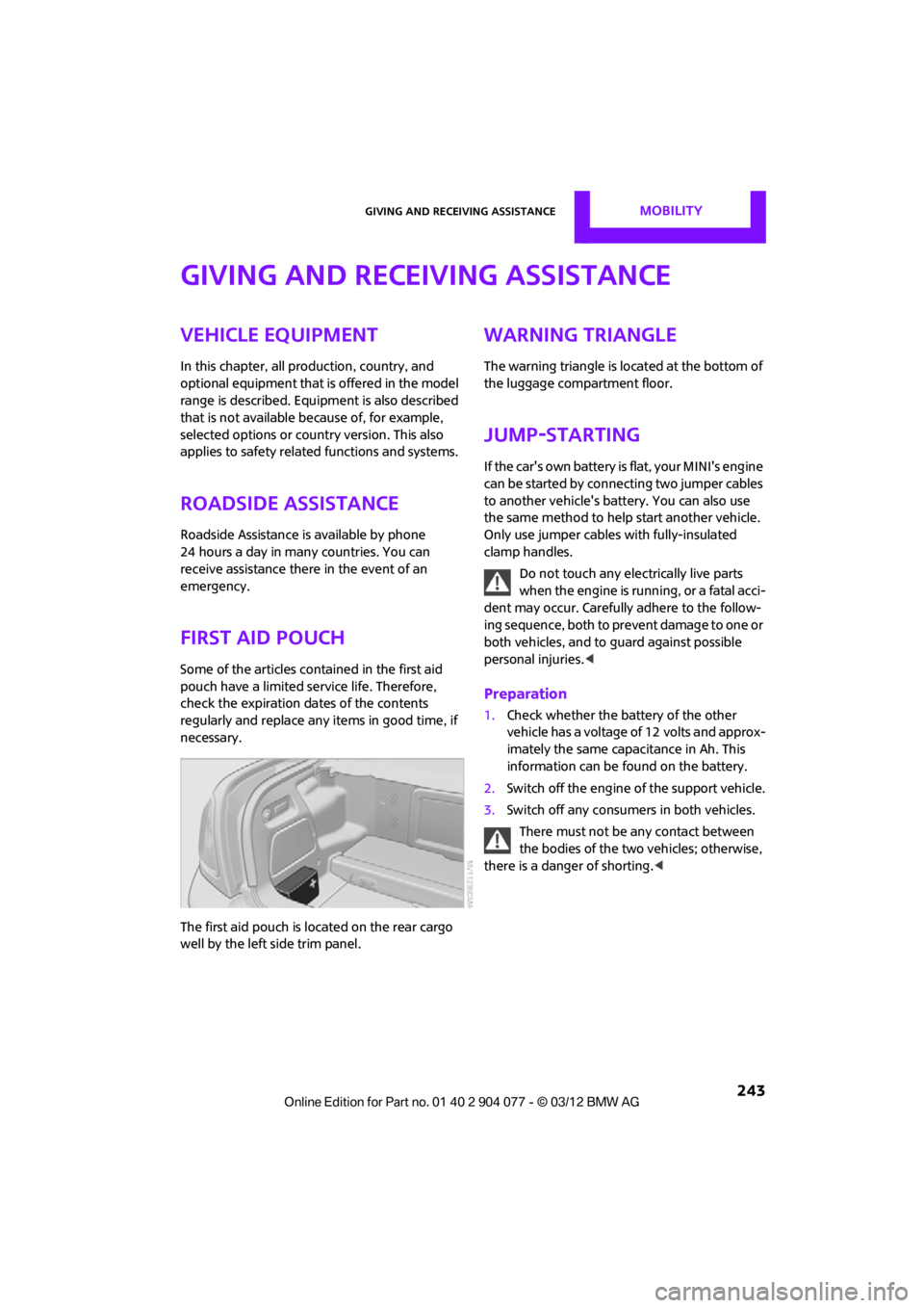
The first aid pouch is located on the rear cargo
well by the left side trim panel.
Warning triangle
The warning triangle is located at the bottom of
the luggage compartment floor.
Jump-starting
If the car's own battery is flat, your MINI's engine
can be started by connecting two jumper cables
to another vehicle's battery. You can also use
the same method to help start another vehicle.
Only use jumper cables with fully-insulated
clamp handles.
Do not touch any electrically live parts
w hen the e ngin e is run ning, or a fatal acci-
dent may occur. Carefully adhere to the follow-
ing sequence, both to prevent damage to one or
both vehicles, and to guard against possible
personal injuries. <
Preparation
1.Check whether the battery of the other
vehicle has a voltage of 12 volts and approx-
imately the same capacitance in Ah. This
information can be found on the battery.
2. Switch off the engine of the support vehicle.
3. Switch off any consumers in both vehicles.
There must not be any contact between
the bodies of the two vehicles; otherwise,
there is a danger of shorting. <
00320051004F004C00510048000300280047004C0057004C005200510003
Page 245 of 283
MOBILITYGiving and receiving assistance
244
Connecting jumper cables
Connect the jumper cables in the correct
order, so that no sparks which could cause
injury occur.<
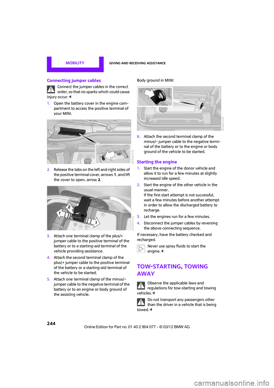
1. Open the battery cover in the engine com-
partment to access the positive terminal of
your MINI.
2. Release the tabs on the left and right sides of
the positive terminal cover, arrows 1, and lift
the cover to open, arrow 2.
3. Attach one terminal clamp of the plus/+
jumper cable to the positive terminal of the
battery or to a starting-aid terminal of the
vehicle providing assistance.
4. Attach the second terminal clamp of the
plus/+ jumper cable to the positive terminal
of the battery or a starting-aid terminal of
the vehicle to be started.
5. Attach one terminal clamp of the minus/–
jumper cable to the negative terminal of the
battery or to an engine or body ground of
the assisting vehicle. Body ground in MINI:
6.
Attach the second te rminal clamp of the
minus/– jumper cable to the negative termi-
nal of the battery or to the engine or body
ground of the vehicle to be started.
Starting the engine
1. Start the engine of the donor vehicle and
allow it to run for a few minutes at slightly
increased idle speed.
2. Start the engine of the other vehicle in the
usual manner.
If the first start attempt is not successful,
wait a few minutes before another attempt
in order to allow the discharged battery to
recharge.
3. Let the engines run for a few minutes.
4. Disconnect the jumper cables by reversing
the above connecting sequence.
If necessary, have the battery checked and
recharged. Never use spray fluids to start the
engine. <
Tow-starting, towing
away
Observe the applicable laws and
regulations for tow-starting and towing
vehicles. <
Do not transport any passengers other
than the driver in a vehicle that is being
towed. <
00320051004F004C00510048000300280047004C0057004C005200510003
Page 247 of 283
MOBILITYGiving and receiving assistance
246
Only attach the tow bar to the tow fittings,
as attachment to other vehicle parts can
lead to damage. <
Towing with a tow rope
When starting off in the towing vehicle, make
sure that the tow rope is taut.
To avoid jerking and the associated
stresses on vehicle components when
towing, always use nylon ropes or nylon straps.
Attach the tow rope to the tow fittings only, as
attaching it to other pa rts of the vehicle could
result in damage. <
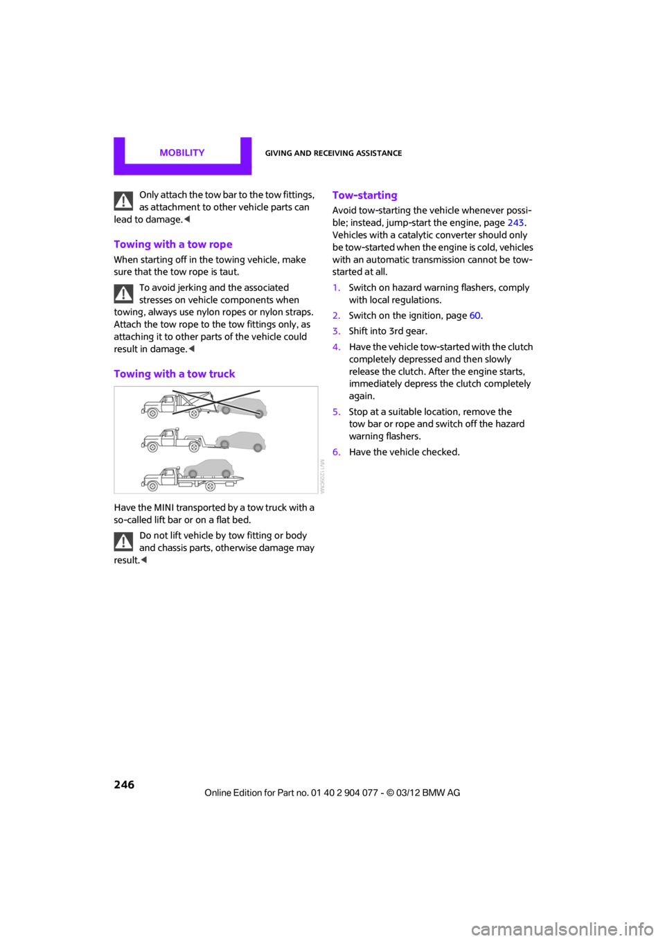
Towing with a tow truck
Have the MINI transported by a tow truck with a
so-called lift bar or on a flat bed.
Do not lift vehicle by tow fitting or body
and chassis parts, otherwise damage may
result. <
Tow-starting
Avoid tow-starting the vehicle whenever possi-
ble; instead, jump-start the engine, page 243.
Vehicles with a catalyti c converter should only
be tow-started when the engine is cold, vehicles
with an automatic transmission cannot be tow-
started at all.
1. Switch on hazard warning flashers, comply
with local regulations.
2. Switch on the ignition, page 60.
3. Shift into 3rd gear.
4. Have the vehicle tow-started with the clutch
completely depressed and then slowly
release the clutch. After the engine starts,
immediately depress the clutch completely
again.
5. Stop at a suitable location, remove the
tow bar or rope and switch off the hazard
warning flashers.
6. Have the vehicle checked.
00320051004F004C00510048000300280047004C0057004C005200510003
Page 269 of 283

268
REFERENCEEverything from A to Z
Everything from A to Z
Index
A
ABS Antilock Brake System83
Accessories, see Vehicle equipment 4
Acknowledgment signals for
locking/unlocking vehicle 30
Activated-charcoa l filter for
automatic climate
control 105
Adaptive Light Control 97
Adding engine oil 223
Additives
– coolant 224
– engine oil 223
Address, entering 132
Address for navigation
– entering 126,132
Adjusting temperature inside the car, refer to Air
conditioner 102
Adjusting temperature inside the car, refer to Automatic
climate control 103
Adjusting the tone during audio operation, refer to
Tone control 147
Airbags 93
– sitting safely 50
– warning lamp 94
Air conditioner 101
Air conditioning mode
– air conditioner 102
– automatic climate control 103
– ventilation 106
Air distribution
– automatic 104
– individual 103
– manual 103 Air flow rate
102,104
– air conditioning system 102
– automatic climate
control 104
– heating, ventilation 102
Airing, refer to Ventilation106
Air outlets, refer to Air vents 101
Air pressure, checking, refer to
Tire inflation pressure 209
Air recirculation, refer to Recirculated-air
mode 102,104
Air supply
– air conditioner 102
– automatic climate control 103
– ventilation 106
Air vents 101
AKI, refer to Fuel grade 207
Alarm system 34
All-season tires, refer to Winter
tire
s220
Always Open Timer 72
AM, wa
veband 149
Ambient air, refer to
Recirculated-air
mode 102,104
Ambient lighting 100
Antenna, care 227
Antifreeze
– coolant 224
– washer fluid 67
Antilock Brake System ABS 83
Anti-theft alarm system, refer
to Alarm system 34
Anti-theft system 29
Approved axle loads, refer to
Weights 257 Approved engine oils
223
Approved gross vehicle weight, refer to Weights257
Armrest, refer to Center armrest 108
Arrival time
– computer 73
– route guidance 135
Ashtray 109
Assistant systems, refer to
– Dynamic Stability Control DSC 83
Audio 146
– controls 146
– switching on/off 146
– tone control 147
– volume 147
Audio device, external 108
Automatic
– air distribution 104
– air flow rate 104
– cruise control 68
– headlamp control 96
Automatic climate control 101
– automatic air distribution 104
Automatic rear spoiler 85
Automatic transmission with Steptronic 62
– Interlock 63
– overriding selector lever lock 64
– Shiftlock 63
– sport program 64
AUTO program for automatic
climate control 104
Auxiliary phone 182
AUX-In, refer to External audio
device 108
AUX-In connection 159
00320051004F004C00510048000300280047004C0057004C005200510003
Page 271 of 283

REFERENCEEverything from A to Z
270
Carpets, care230
Car phone
– installation location, refer to Center armrest 108
– refer to Telephone 108
Car phone, refer to Telephone 170,180
Car radio, refer to Radio 149
Car wash, care 227
Car washes 227
Catalytic conver ter, refer to
Hot exhaust system 115
CD, audio playback 157
CD player 157
– controls 146
– fast forward/reverse 158
– random order 158
– selecting a track 157
– switching on/off 146
– tone control 147
– volume 147
Center armrest 108
Center brake lamp 236
Center console, refer to Around the center
console 14
Central locking system 29
– Comfort Access 36
– from inside 32
– from outside 29
Changing bulbs 232
Changing the language on the Control Display 80
Changing the measurement units on the Control
Display 74
Changing wheels 239
Charging the battery 241
Chassis number, refer to
Engine compartment 221
Check Control 77
Child restraint fixing system
LATCH 57
Child restraint systems 56
Child seats 56 Chrome parts, care
229
Chrome parts, refer to Care 227
Cigarette lighter 109
Cleaning headlamps 67
– washer fluid 67
Clock
– setting time 76
– 12 h/24 h mode 76
Closing
– from inside 32
– from outside 29
Cl ot
hes hooks 108
Cockpit 10
Cold start, refer to Starting the engine 61
Comfort Access 36
– replacing the battery 38
– what to observe before
entering a car wash 37
Comfort area, refer to Around the center console 14
Compartment for remote control, refer to Ignition
lock 60
Computer 71
– displays on Control Display 73
Condensation, refer to When the vehicle is parked 116
Condition Based Service CBS 225
Configuring settings, refer to
Personal Profile 28
Connecting vacuum cleaner, refer to Connecting electrical
appliances 110
Consumption, refer to Average fuel consumption 72
Contact editing 178
Contacts 177,194
– new contact 195
Continuing route guidance 135
Control Display
– settings 73 Control Display, refer to iDrive
– switching on/off
17
Control Display, refer to Onboard computer 17
Controls and displays 10
Control stick, refer to Onboard computer 17
Control unit, refer to Onboard computer 17
Convenience operation
– convertible top 32
– windows 30
Convenient access, refer to
Comfort Access 36
Convenient star t, refer to
Starting the engine 61
Convertible top 39
– manual 44
– mechanical 44
Coolant 224
– checking level 224
– filling 224
Coolant temperature 224
Cooling, maximum 104
Cooling fluid, refer to
Coolant 224
Copyright 2
Corneri n
g li
ght, refer to
Adaptive Light Control 97
Criteria for route 135
Cruise control
– indicator lamp 13
Cruising range 71
Cupholders 109
Curb weight, refer to Weights 257
Current fuel consumption 72
Current playback
– external devices 162
D
Dashboard, refer to Cockpit 10
Dashboard instruments, refer to Displays 12
Dashboard lighting, refer to Instrument lighting 99
00320051004F004C00510048000300280047004C0057004C005200510003