2012 MERCEDES-BENZ SLS AMG COUPE service reset
[x] Cancel search: service resetPage 17 of 288

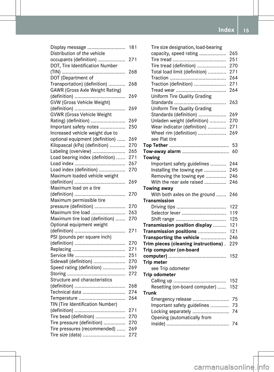
Display message ............................ 181
Distribution of the vehicle
occupants (definition) ....................271
DOT, Tire Identification Number
(TIN) ............................................... 268
DOT (Department of
Transportation) (definition) ............268
GAWR (Gross Axle Weight Rating)
(definition) ..................................... 269
GVW (Gross Vehicle Weight)
(definition) ..................................... 269
GVWR (Gross Vehicle Weight
Rating) (definition) .........................269
Important safety notes ..................250
Increased vehicle weight due to
optional equipment (definition) ......269
Kilopascal (kPa) (definition) ...........270
Labeling (overview) ........................265
Load bearing index (definition) ......271
Load index ..................................... 267
Load index (definition) ...................270
Maximum loaded vehicle weight
(definition) ..................................... 269
Maximum load on a tire
(definition) ..................................... 270
Maximum permissible tire
pressure (definition) ....................... 270
Maximum tire load .........................263
Maximum tire load (definition) .......270
Optional equipment weight
(definition) ..................................... 271
PSI (pounds per square inch)
(definition) ..................................... 270
Replacing ....................................... 271
Service life ..................................... 251
Sidewall (definition) .......................270
Speed rating (definition) ................269
Storing ........................................... 272
Structure and characteristics
(definition) ..................................... 268
Technical data ............................... 274
Temperature .................................. 264
TIN (Tire Identification Number)
(definition) ..................................... 271
Tire bead (definition) ......................270
Tire pressure (definition) ................270
Tire pressures (recommended) ......269
Tire size (data) ............................... 272Tire size designation, load-bearing
capacity, speed rating .................... 265
Tire tread ....................................... 251
Tire tread (definition) .....................270
Total load limit (definition) .............271
Traction ......................................... 264
Traction (definition) .......................271
Tread wear ..................................... 264
Uniform Tire Quality Grading
Standards ...................................... 263
Uniform Tire Quality Grading
Standards (definition) ....................269
Unladen weight (definition) ............270
Wear indicator (definition) .............271
Wheel rim (definition) ....................269
see Flat tire
Top Tether ............................................ 53
Tow-away alarm .................................. 60
Towing Important safety guidelines ...........244
Installing the towing eye ................245
Removing the towing eye ...............246
With the rear axle raised ................246
Towing away
With both axles on the ground .......246
Transmission
Driving tips .................................... 122
Selector lever ................................ 119
Shift range ..................................... 125
Transmission position display ......... 121
Transmission positions .................... 121
Transporting the vehicle .................. 246
Trim pieces (cleaning instructions) . 229
Trip computer (on-board
computer) .......................................... 152
Trip meter see Trip odometer
Trip odometer
Calling up ....................................... 152
Resetting (on-board computer) ......152
Trunk
Emergency release ..........................75
Important safety guidelines .............73
Locking separately ...........................74
Opening (automatically from
inside) .............................................. 74Index15
Page 23 of 288

General notes
i USA only:
This device complies with Part 15 of the
FCC Rules. Operation is subject to the
following two conditions:
1. This device may not cause harmful
interference, and
2. this device must accept any interference
received, including interference that may
cause undesired operation.
Any unauthorized modification to this
device could void the user’s authority to
operate the equipment.
The Product label with FCC ID and IC
certification number can be found in the
battery case of the SmartKey.
i Canada only:
This device complies with RSS-210 of
Industry Canada. Operation is subject to
the following two conditions:
1. This device may not cause interference,
and
2. this device must accept any interference
received, including interference that may
cause undesired operation of the device.
Any unauthorized modification to this
device could void the user’s authority to
operate the equipment.
The Product label with FCC ID and IC
certification number can be found in the
battery case of the SmartKey.
Diagnostics connection
GWARNING
If you connect equipment to the diagnostics
connection, it can affect the operation of the
vehicle systems. This can impair the operating
safety of your vehicle while driving. There is a
risk of accident.
Do not connect any equipment to the
diagnostics connection.
GWARNING
Loose equipment or equipment cables that
are connected to the diagnostics connection
can obstruct the area around the pedals. The
equipment or the cables could get between
the pedals in the event of sudden braking or
acceleration. As a result, the movement of the
pedals may be impaired. There is a risk of
accident.
Do not attach any equipment or cables in the
driver footwell.
! If the engine is switched off and
equipment on the diagnostics connection
is used, the starter battery may discharge.
The diagnostics connection is only intended
for the connection of diagnostic equipment at
a qualified specialist workshop.
Connecting equipment to the diagnostics
connection can, for example, lead to
emissions monitoring information being
reset. This may lead to the vehicle failing to
meet the requirements of the next emissions
test during the main inspection.
Qualified specialist workshop
An authorized Mercedes-Benz Center is a
qualified specialist workshop. It has the
necessary specialist knowledge, tools and
qualifications to correctly carry out the work
required on your vehicle. This is especially the
case for work relevant to safety.
Observe the notes in the Maintenance
Booklet.
Always have the following work carried out at
an authorized Mercedes-Benz Center:
R work relevant to safety
R service and maintenance work
R repair work
R alterations, installation work and
modifications
R work on electronic components
Introduction21Z
Page 224 of 288

outside temperature. For information on
the mixing ratio ( Y page 284).XTo open: pull cap : upwards by the tab.XAdd the premixed washer fluid.XTo close: press cap : onto the filler neck
until it engages.
Maintenance
Service interval display
Service messages
Information on the type of service and service
intervals (see separate Maintenance
Booklet).
You can obtain further information from an
authorized Mercedes-Benz Center or at
http://www.mbusa.com (USA only).
The service interval message informs you of
the next service due date.
If a service due date has been exceeded, you
also hear a warning tone.
The multifunction display shows a service
message for several seconds, e.g.:
Next service A in .. days
Service A due
Service A overdue by .. days
The letter indicates which service is due. A
stands for a minor service and B for a major
service. A number or another letter may be
displayed after the letter. This figure indicates
any necessary additional maintenance work
to be performed.
You can obtain further information from an
authorized Mercedes-Benz Center.
The service interval display does not take into
account any periods of time during which the
battery is disconnected.
Maintaining the time-dependent service
schedule:XNote down the service due date displayed
in the multifunction display before
disconnecting the battery.
or
XSubtract the battery disconnection periods
from the service date shown on the display
after reconnecting the battery.
i The service interval display does not
provide any information regarding the
engine's oil level. Observe the notes on the
engine oil level ( Y page 219).
Hiding a service message
XPress the % or a button on the
steering wheel.
Displaying service messages
XSwitch on the ignition.XPress the = or ; button on the
steering wheel to select the Serv. menu.XPress the 9 or : button to select the
ASSYST PLUS submenu and confirm with
a .
The service due date appears in the
multifunction display.
Please bear the following in mind
Resetting the service interval display
A qualified specialist workshop, e.g. an
authorized Mercedes-Benz Center, will reset
the service interval display after the
necessary service work has been carried out.
Further information, on maintenance for
example, can be obtained at an authorized
Mercedes-Benz Center or directly from
Mercedes-Benz.
! If the service interval display has been
reset unintentionally, have the setting
corrected at a Mercedes-Benz Center.
222MaintenanceMaintenance and care