2012 MERCEDES-BENZ SLK55AMG towing
[x] Cancel search: towingPage 275 of 334
Useful information
............................274
Where will I find...? ...........................274
Flat tire .............................................. 275
Battery ............................................... 282
Jump-starting .................................... 285
Towing and tow-starting ..................287
Fuses .................................................. 289 273Breakdown assistance
Page 276 of 334
Useful information
i This Operator's Manual describes all
models and all standard and optional
equipment of your vehicle available at the
time of publication of the Operator's
Manual. Country-specific differences are
possible. Please note that your vehicle may
not be equipped with all features
described. This also applies to safety-
related systems and functions.
i Please read the information on qualified
specialist workshops (Y page 23).Where will I find...?
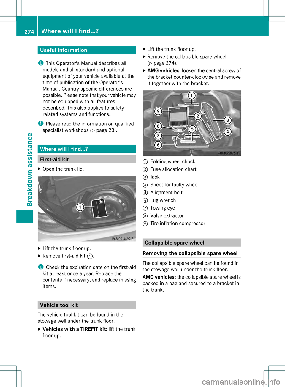
First-aid kit
X Open the trun klid. X
Lift the trunk floor up.
X Remove first-aid kit 0002.
i Check the expiration date on the first-aid
kit at least once a year. Replace the
contents if necessary, and replace missing
items. Vehicle tool kit
The vehicle tool kit can be found in the
stowage well under the trunk floor.
X Vehicles with a TIREFIT kit: lift the trunk
floor up. X
Lift the trunk floor up.
X Remove the collapsible spare wheel
(Y page 274).
X AMG vehicles: loosen the central screw of
the bracket counter-clockwise and remove
it together with the bracket. 0002
Folding wheel chock
0003 Fuse allocation chart
0023 Jack
0022 Shee tfor faulty wheel
0020 Alignmen tbolt
0021 Lug wrench
0014 Towing eye
0015 Valve extractor
0016 Tire inflation compressor Collapsible spare wheel
Removing the collapsible sparew heel The collapsible spare wheel can be found in
the stowage well unde
rthe trunk floor.
AMG vehicles: the collapsible spare wheel is
packed in a bag and secured to a bracket in
the trunk. 274
Where will I find...?Breakdown assistance
Page 277 of 334
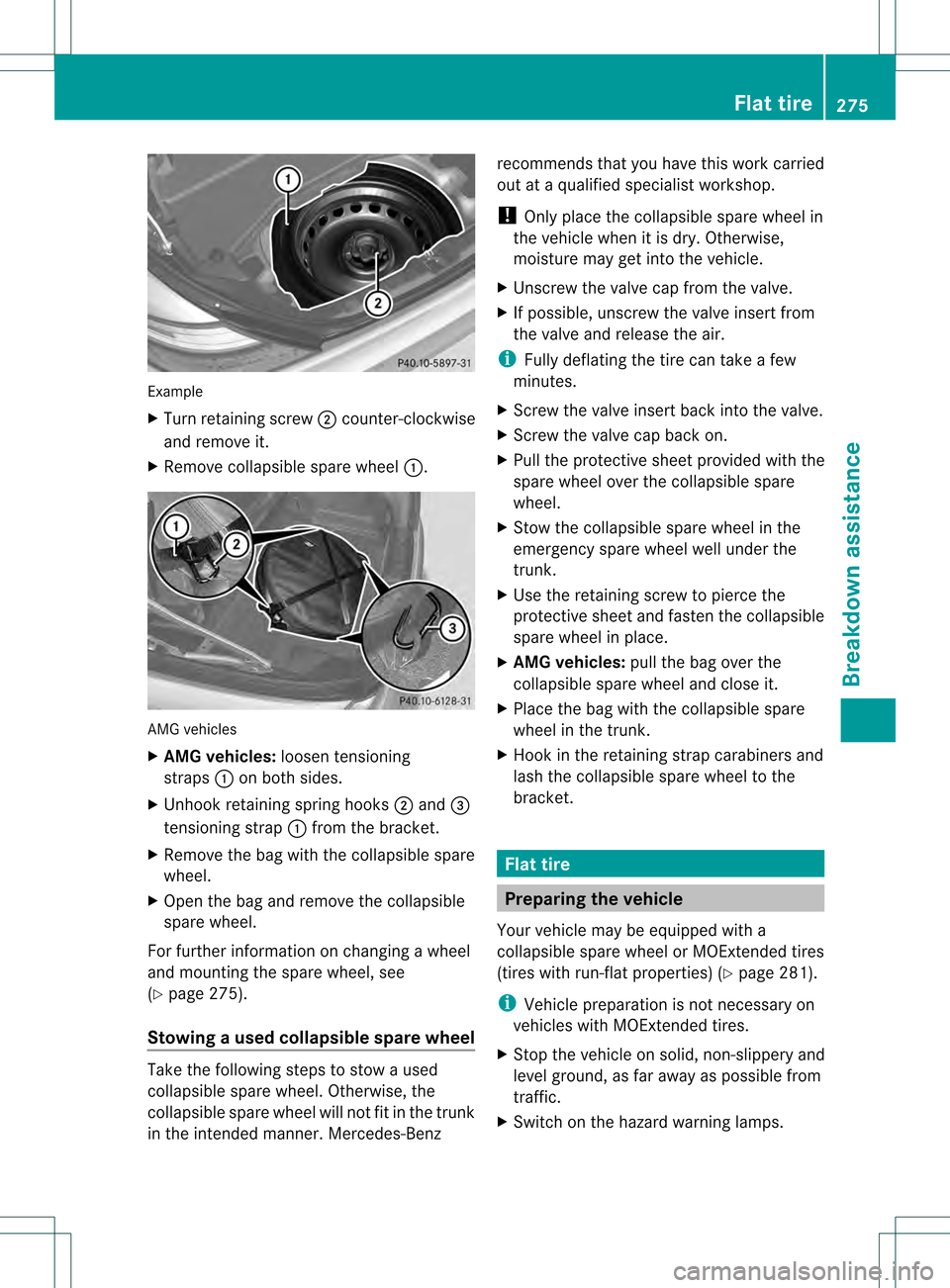
Example
X
Turn retaining screw 0003counter-clockwise
and remove it.
X Remove collapsible spare wheel 0002.AMG vehicles
X
AM Gvehicles: loosentensioning
straps 0002on both sides.
X Unhook retaining spring hooks 0003and 0023
tensioning strap 0002from the bracket.
X Remove the bag with the collapsible spare
wheel.
X Open the bag and remove the collapsible
spare wheel.
For further information on changing a wheel
and mounting the spare wheel, see
(Y page 275).
Stowing aused collapsible spare wheel Take the following steps to stow a used
collapsible spare wheel. Otherwise, the
collapsible spare wheel will not fit in the trunk
in the intended manner. Mercedes-Benz recommends that you have this work carried
out at a qualified specialist workshop.
!
Only place the collapsible spare wheel in
the vehicle when it is dry. Otherwise,
moisture may get into the vehicle.
X Unscrew the valve cap from the valve.
X If possible, unscrew the valve insert from
the valve and release the air.
i Fully deflating the tire can take a few
minutes.
X Screw the valve insert back into the valve.
X Screw the valve cap back on.
X Pull the protective sheet provided with the
spare wheel over the collapsible spare
wheel.
X Stow the collapsible spare wheel in the
emergency spare wheel well under the
trunk.
X Use the retaining screw to pierce the
protective sheet and fasten the collapsible
spare wheel in place.
X AMG vehicles: pull the bag over the
collapsible spare wheel and close it.
X Place the bag with the collapsible spare
wheel in the trunk.
X Hook in the retaining strap carabiners and
lash the collapsible spare wheel to the
bracket. Flat tire
Preparing the vehicle
Your vehicle may be equipped with a
collapsible spare wheel or MOExtended tires
(tires with run-flat properties) (Y page 281).
i Vehicle preparation is not necessary on
vehicles with MOExtended tires.
X Stop the vehicle on solid, non-slippery and
level ground, as far away as possible from
traffic.
X Switch on the hazard warning lamps. Flat tire
275Breakdown assistance
Page 289 of 334
Towing and tow-starting
Important safety notes
G
WARNING
If you tow the vehicle, you must use a rigid
towing ba rif:
R the engine is not running.
R there is a brake system malfunction.
R there is a malfunction in the power supply
or the vehicle's electrical system.
The power assistance for the steering and the
brake force booster do not work when the
engine is not running. You will need more
force to steer and brake, you may have to
depress the brake pedal with maximu mforce.
Before towing away, make sure that the
steering can be moved and is not locked.
If you tow or tow-start another vehicle, its
weight must not exceed the maximum
permissible gross vehicle weight of your
vehicle.
It is better to have the vehicle transported
than to have it towed.
! The vehicle can be towed a maximum of
30 miles (50km). The towing speed of
30 mph (50 km/h) must not be exceeded.
If the vehicle has to be towed more than
30 miles (50km), the entire vehicle must be
raised and transported.
! Make sure that the electric parking brake
is released. If the electric parking brake is
faulty, visit a qualified specialist workshop.
! Only secure the tow rope or tow bar at the
towing eyes. Otherwise, the vehicle could
be damaged.
! Do not use the towing eye for recovery,
as this could damage the vehicle. If in
doubt, recover the vehicle with a crane.
! Drive slowly and smoothly when towing.
Excessive tractive power could otherwise
damage the vehicles. !
Do not tow with sling-type equipment.
This could damage the vehicle.
! On vehicles with KEYLESS-GO, use the
SmartKey instead of the Start/Stop
button. Turn the SmartKey to position 2in
the ignition lock and shift the automatic
transmission to N. Then, turn the SmartKey
back to 0and leave it in the ignition lock.
When towing a vehicle with an automatic
transmission, the transmission must be in
position N.
The battery must be connected and charged.
Otherwise, you:
R cannot turn the SmartKey to position 2in
the ignition lock
R cannot shift the transmission to position
N on vehicles with automatic transmission
Vehicles with automatic transmission:
release the selector lever lock manually to
move it out of position P(Ypage 146).
i Switch off the automatic locking feature
(Y page 75) You could otherwise be locked
out when pushing or towing the vehicle. Installing/removing the towing eye
Installing the towing eye X
Remove the towing eye from the vehicle
tool kit (Y page 274). G
WARNING
The exhaust tail pipe may be hot. You could
burn yourself if you touch the tail pipe. Be
particularly careful when removing the rear
cover.
The mountings for the removable towing eyes
are located in the bumpers. They are at the
front and at the rear, under the covers. Towing and tow-starting
287Breakdown assistance Z
Page 290 of 334

X
Press the mark on cover 0002inwards in the
direction of the arrow.
X Take cover 0002off the opening.
X Screw the towing eye in clockwise to the
stop and tighten it.
Removing the towing eye X
Loosen the towing eye and unscrew it.
X Attach cover 0002to the bumper and press
until it engages.
X Place the towing eye in the vehicle tool kit. Towing the vehicle with the rear axle
raised
When towing your vehicle with the rear axle
raised, it is importan tthat you observe the
safety instructions (Y page 287).
! The ignition must be switched off if you
are towing the vehicle with the rear axle
raised. Intervention by ESP ®
could
otherwise damage the brake system. X
Switch on the hazard warning lamps
(Y page 108).
X Turn the SmartKey to position 0in the
ignition lock and remove the SmartKey
from the ignition lock.
X When leaving the vehicle, take the
SmartKey or the KEYLESS-GO key with you. Towing
avehicle with both axles on
the ground
When having your vehicle towed, observe the
important safety notes (Y page 287). G
WARNING
The power assistance for the steering and the
brake force booster do not work when the
engine is not running. You will then need
much more effort to brake and steer the
vehicle .Adapt your style of driving
accordingly.
X Switch on the hazard warning lamps
(Y page 108).
i When towing with the hazard warning
lamps switched on, use the combination
switch as usual to signal a change of
direction. In this case, only the turn signals
for the desired direction flash. When the
combination switch is reset, the hazard
warning lamps start flashing again.
X Turn the SmartKey to position 2in the
ignition lock.
X When the vehicle is stationary, depress the
brake pedal and keep it depressed.
X Vehicles with manual transmission:
depress the clutch pedal.
X Shift to neutral.
or
X Vehicles with automatic transmission:
shift the automatic transmission to
position N.
X Release the brake pedal.
X Release the parking brake. 288
Towing and tow-startingBreakdown assistance
Page 291 of 334
Transporting the vehicle
The towing eye can be used to pull the vehicle
onto a trailer or transporter for transporting
purposes.
X Vehicles with manual transmission:
shift to neutral.
X Vehicles with automatic transmission:
turn the SmartKey to position 2in the
ignition lock.
X Move the selecto rlever to N.
As soon as the vehicle is loaded:
X Preven tthe vehicle from rolling away by
applying the parking brake.
X Vehicles with manual transmission:
shift to first gear or reverse gear.
X Vehicles with automatic transmission:
move the selector lever to P.
X Turn the SmartKey to position 0in the
ignition lock and remove the SmartKey
from the ignition lock.
X Secure the vehicle.
! Only lash the vehicle down by the wheels
or wheel rims, not by parts of the vehicle
such as axle or steering components.
Otherwise, the vehicle could be damaged. Tow-starting (emergency starting)
When tow-starting your vehicle, it is
important that you follow the safety
instructions (Y page 287).
! Vehicles with automatic transmission
must not be started by tow-starting. This
could otherwise damage the transmission.
For further information on "Jump-starting"
see (Y page 285).
Before tow-starting the following conditions
must be fulfilled:
R the battery is connected.
R the engine has cooled down.
R the catalytic converter has cooled down. X
Switch on the hazard warning lamps
(Y page 108).
X Install the towing eye (Y page 287).
X Secure the rigid towing bar or the towing
rope.
X Depress and hold the brake pedal.
X Turn the SmartKey to position 2in the
ignition lock.
X Depress the clutch pedal and keep it
depressed.
X Shift to neutral.
X Release the brake pedal.
X Tow-start the vehicle.
X Shift to second gear.
X Release the clutch pedal slowly;d o not
depress the accelerator pedal while doing
so.
The engine is started.
X Depress the clutch pedal and shift to
neutral.
X Stop at a suitable place.
X Depress the parking brake.
X Remove the rigid towing bar or towing rope.
X Remove the towing eye (Y page 288).
X Switch off the hazard warning lamps. Fuses
Important safety notes
G
WARNING
Only use fuses that have been approved for
Mercedes-Benz vehicles and that have the
correct fuse rating for the systems
concerned. Do not attempt to repair or bridge
faulty fuses. Using fuses that have not been
approved or attempting to repair or bridge
faulty fuses could cause the fuse to be
overloaded and result in afire. Have the cause
traced and rectified at a qualified specialist
workshop.
The fuses in your vehicle serve to close down
faulty circuits. If afuse blows, all the Fuses
289Breakdown assistance Z
Page 307 of 334
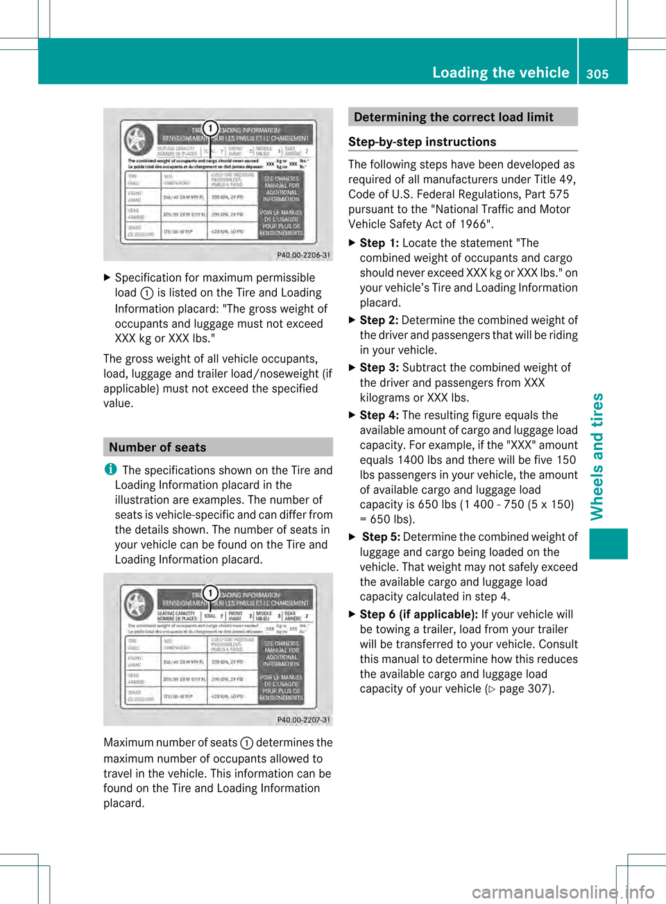
X
Specification for maximum permissible
load 0002is listed on the Tire and Loading
Information placard: "The gross weight of
occupants and luggage mus tnot exceed
XXX kg or XXX lbs."
The gross weight of all vehicle occupants,
load, luggage and trailer load/noseweight (if
applicable) must not exceed the specified
value. Number of seats
i The specifications shown on the Tire and
Loading Information placard in the
illustration are examples. The number of
seats is vehicle-specific and can differ from
the details shown. The number of seats in
your vehicle can be found on the Tire and
Loading Information placard. Maximum number of seats
0002determines the
maximum number of occupants allowed to
travel in the vehicle. This information can be
found on the Tire and Loading Information
placard. Determining the correct load limit
Step-by-step instructions The following steps have been developed as
required of all manufacturers under Title 49,
Code of U.S. Federal Regulations, Part 575
pursuant to the "National Traffic and Motor
Vehicle Safety Act of 1966".
X
Step 1: Locate the statement "The
combined weight of occupant sand cargo
should neve rexceed XXX kg or XXX lbs." on
your vehicle’s Tire and Loading Information
placard.
X Ste p2:Determine the combined weight of
the driver and passengers tha twill be riding
in your vehicle.
X Step 3: Subtract the combined weight of
the drive rand passengers from XXX
kilograms or XXX lbs.
X Ste p4:The resulting figure equals the
available amount of cargo and luggage load
capacity. For example, if the "XXX" amount
equals 1400 lbs and there will be five 150
lbs passengers in your vehicle, the amount
of available cargo and luggage load
capacity is 650 lbs (1 400 - 750 (5 x 150)
= 650 lbs).
X Step 5: Determine the combined weight of
luggage and cargo being loaded on the
vehicle. That weight may not safely exceed
the available cargo and luggage load
capacity calculated in step 4.
X Step 6 (if applicable): If your vehicle will
be towing a trailer, load from your trailer
will be transferred to your vehicle. Consult
this manual to determine how this reduces
the available cargo and luggage load
capacity of your vehicle ( Ypage 307). Loading the vehicle
305Wheels and tires Z
Page 308 of 334
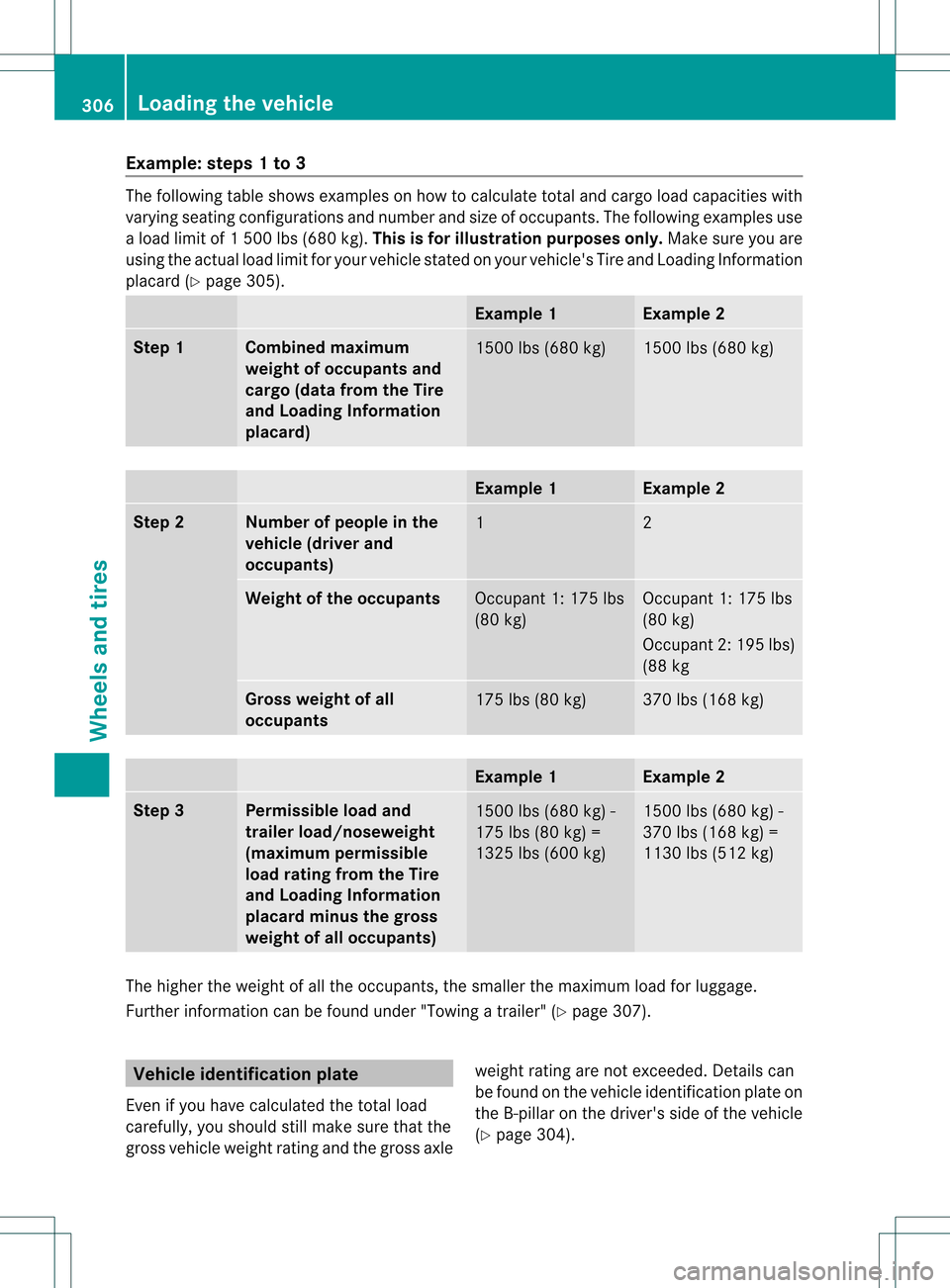
Example: steps 1 to 3
The following table shows examples on how to calculate total and cargo load capacities with
varying seating configurations and number and size of occupants. The following examples use
a load limit of 1500 lbs (680 kg). This is for illustration purposes only. Make sure you are
using the actual load limit for you rvehicle stated on your vehicle's Tire and Loading Information
placard (Y page 305). Example 1 Example 2
Step 1 Combined maximum
weight of occupants and
cargo (data from the Tire
and Loading Information
placard)
1500 lbs (680 kg) 1500 lbs (680 kg)
Example 1 Example 2
Step 2 Number of people in the
vehicle (driver and
occupants)
1 2
Weight of the occupants
Occupant 1: 175 lbs
(80 kg) Occupant 1: 175 lbs
(80 kg)
Occupant 2: 195 lbs)
(88 kg
Gross weight of all
occupants
175 lbs (80 kg) 370 lbs (168 kg)
Example 1 Example 2
Step 3 Permissible load and
trailer load/noseweight
(maximum permissible
load rating from the Tire
and Loading Information
placard minus the gross
weight of all occupants)
1500 lbs (680 kg) -
175 lbs (80 kg) =
1325 lbs (600 kg) 1500 lbs (680 kg) -
370 lbs (168 kg) =
1130 lbs (512 kg)
The higher the weight of all the occupants, the smaller the maximum load for luggage.
Further information can be found under "Towing atrailer" (Y page 307). Vehicle identification plate
Even if you have calculated the total load
carefully, you should still make sure that the
gross vehicle weight rating and the gross axle weight rating are not exceeded. Details can
be found on the vehicle identification plate on
the B-pillar on the driver's side of the vehicle
(Y page 304). 306
Loading the vehicleWheels and tires