2012 MERCEDES-BENZ SLK55AMG clock
[x] Cancel search: clockPage 150 of 334
X
Completely insert the fille rneck of the fuel
pump nozzle into the tank and refuel.
X Only fill the tank until the pump nozzle
switches off.
i Do not add any more fuel after the pump
stops filling for the first time. Otherwise,
fuel may leak out.
Closing X
Replace the cap on the filler necka nd turn
clockwise until it engages audibly.
X Close fuel fille rflap 0002.
i If you drive with the fuel filler cap open,
reserve fuel warning lamp 0010flashes .In
addition, the 000ECheck Engine warning
lamp may light up. Amessage appears in
the multifunction display (Y page 219).
For further information on warning and
indicator lamps in the instrument cluster,
see (Y page 234). 148
RefuelingDriving and parking
Page 182 of 334

Useful information
i This Operator's Manual describes all
models and all standard and optional
equipment of your vehicle available at the
time of publication of the Operator's
Manual. Country-specific differences are
possible. Please note that your vehicle may
not be equipped with all features
described. This also applies to safety-
related systems and functions.
i Please read the information on qualified
specialist workshops (Y page 23).Important safety notes
You will find an illustration of the instrument
cluster in the "At a glance" section
(Y page 27). G
WARNING
The driver's concentration must always be
directed primarily at road traffic.
For your safety and the safety of others,
selecting features through the multifunction
steering wheel should only be done by the
driver when traffic and road conditions permit
it to be done safely.
Bear in mind that at a speed of only 30 mph
(approximately 50 km/h), the vehicle covers
a distance of 44 feet (approximately 14 m) per
second. G
WARNING
No messages will be displayed if either the
instrument cluster or the multifunction
display is inoperative.
As a result, you will not be able to see
information about your driving conditions,
such as
R speed
R outside temperature
R warning/indicato rlamps R
malfunction/warning messages
R failure of any systems
Driving characteristics may be impaired.
If you must continue to drive, do so with added
caution .Contactana uthorized Mercedes-
Ben zCenter as soon as possible. G
WARNING
Malfunction and warning messages are only
indicated for certain systems and are
intentionally not very detailed. The
malfunction and warning messages are
simply a reminder with respect to the
operation of certain systems. They do not
replace the owner's and/or driver's
responsibility to maintain the vehicle's
operating safety. Have all required
maintenance and safety checks performed on
the vehicle. Bring the vehicle to an authorized
Mercedes-Benz Center to address the
malfunction and warning messages. Displays and operation
Instrument lighting
The brightness control knob is located on the
bottom left of the instrument cluster
(Y page 27).
X Turn the brightness control knob clockwise
or counter-clockwise.
Instrument cluster: if the light switch is set
to 0005, 0011or0009, brightness control
takes ambient light into account.
i The light sensor in the instrument cluster
automatically controls the brightness of
the multifunction display.
In daylight, the displays in the instrument
cluster are not illuminated.
Displays and switches in the vehicle
interior: if the light switch is set to 0005,
brightness control takes ambient light into
account. If the light switch is set to 0011or
0009, brightness control does not take
ambient light into account. 180
Displays and operationOn-board computer and displays
Page 185 of 334
Back button
0001
Press briefly:
R
Back
R Switches off the Voice Control
System; see the separate
operating instructions
R Hides display messages or calls
up the last Trip menu function
used
R Exits the telephone book/redial
memory 0001
Press and hold:
R
Calls up the standard display in
the Trip menu
Multifunction display
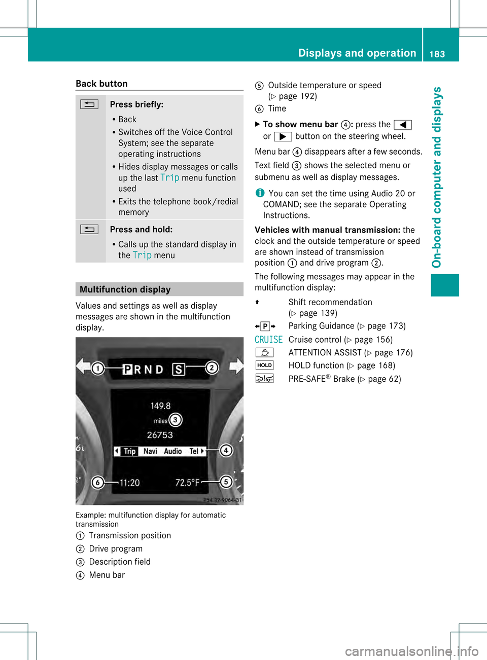
Values and settings as well as display
messages are shown in the multifunction
display. Example: multifunctio
ndisplay for automatic
transmission
0002 Transmission position
0003 Drive program
0023 Description field
0022 Menu bar 0020
Outside temperature or speed
(Ypage 192)
0021 Time
X To show menu bar 0022:press the 0002
or 0005 button on the steering wheel.
Menu bar 0022disappears afte rafew seconds.
Text field 0023shows the selected menu or
submenu as well as display messages.
i You can set the time using Audio 20 or
COMAND; see the separate Operating
Instructions.
Vehicles with manual transmission: the
clock and the outside temperature or speed
are show ninstead of transmission
position 0002and drive program 0003.
The following messages may appear in the
multifunctio ndisplay:
0008 Shift recommendation
(Ypage 139)
00090013000A Parking Guidance (Y page 173)
CRUISE Cruise control (Y
page 156)
0001 ATTENTION ASSIS T(Ypage 176)
0001 HOLD function (Y page 168)
0001 PRE-SAFE ®
Brake (Y page 62) Displays and operation
183On-board computer and displays Z
Page 244 of 334

Useful information
i This Operator's Manual describes all
models and all standard and optional
equipment of your vehicle available at the
time of publication of the Operator's
Manual. Country-specific differences are
possible. Please note that your vehicle may
not be equipped with all features
described. This also applies to safety-
related systems and functions.
i Please read the information on qualified
specialist workshops (Y page 23).Stowage areas
Stowage compartments
Important safety notes G
WARNING
To help avoid personal injury during a collision
or sudden maneuver, exercise care when
storing objects in the vehicle. Put luggage or
cargo in the trun kifpossible.
Keep compartment lids closed. This will help
to prevent stored objects from being thrown
about and injuring vehicle occupants during
R braking
R vehicle maneuvers
R an accident
Stowage compartments in the front Glove box
i
The glove box flap contains brackets for
coins, pens, and credit and service cards. X
To open: pull handle 0002and open glove box
flap 0003.
X To close: fold glove box flap 0003upwards
until it engages.
The glove box can be locked and unlocked
using the key (Y page 68) or using the
mechanical key. X
To lock: insert the mechanical key into the
lock and turn it 90° clockwise to position
0006.
X To unlock: insert the mechanical key into
the lock and turn it 90° counter-clockwise
to position 0005.242
Stowage areasStowage and features
Page 264 of 334
Adding engine oil
G
WARNING
If engine oil comes into contact with hot
engine parts, it may ignite and you could burn
yourself .Do not spill any engine oil on hot
engine parts. H
Environmental note
When adding oil, take care not to spill any. If
oil enters the soil or waterways, it is harmful
to the environment.
! Only use engine oils and oil filters that
have been approved for vehicles with a
service system. You can obtain a list of the
engine oils and oil filters tested and
approved in accordance with the
Mercedes-Benz Specifications for Service
Products at any Mercedes-Benz Service
center.
Damage to the engine or exhaust system is
caused by the following:
R using engine oils and oil filters that have
not been specifically approved for the
service system
R replacing engine oil and oil filters after
the interval for replacement specified by
the service system has been exceeded
R using engine oil additives.
! Do not add too much oil. adding too much
engine oil can result in damage to the
engine or to the catalytic converter. Have
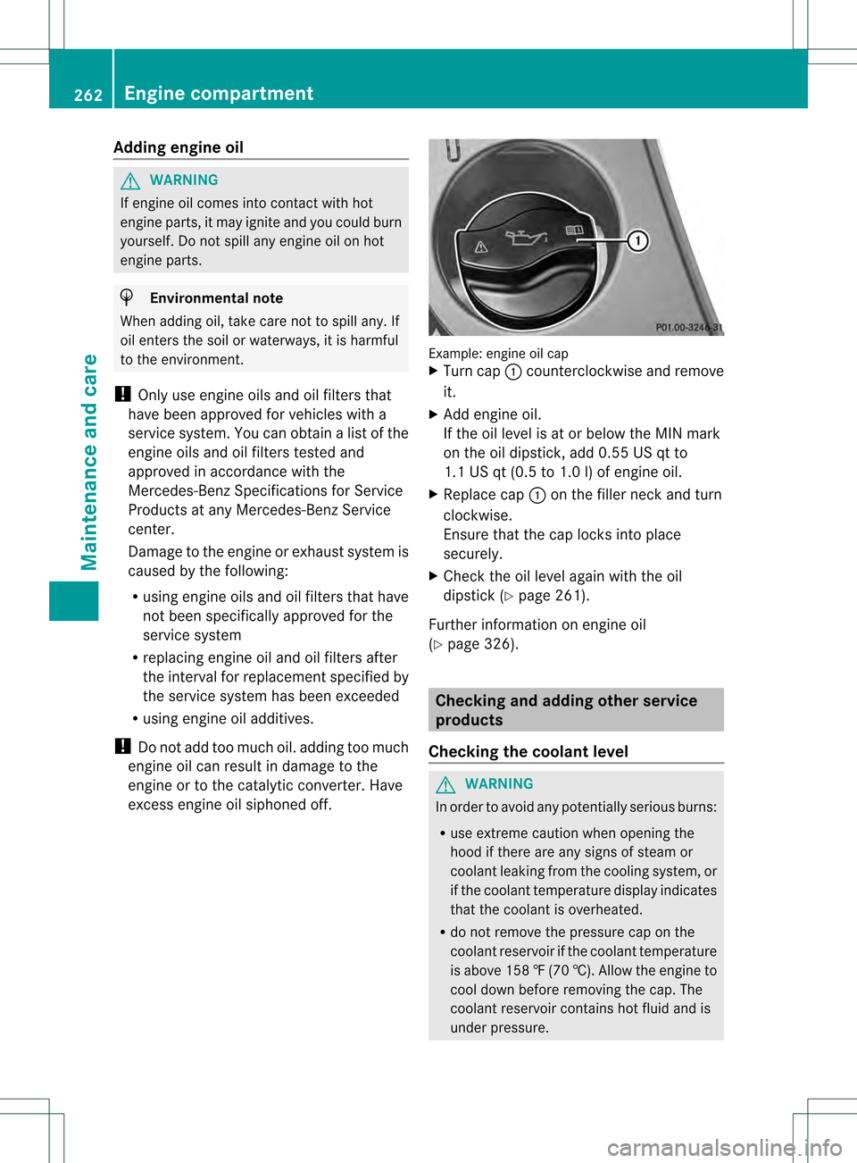
excess engine oil siphoned off. Example: engine oil cap
X
Turn cap 0002counterclockwise and remove
it.
X Add engine oil.
If the oil level is at or below the MIN mark
on the oil dipstick, add 0.55 US qt to
1.1 US qt (0.5 to 1.0 l)of engine oil.
X Replace cap 0002on the filler neck and turn
clockwise.
Ensure that the cap locks into place
securely.
X Check the oil level again with the oil
dipstick (Y page 261).
Further information on engine oil
(Y page 326). Checking and adding other service
products
Checking the coolant level G
WARNING
In order to avoid any potentially serious burns:
R use extreme caution when opening the
hood if there are any signs of steam or
coolant leaking from the cooling system, or
if the coolant temperature display indicates
that the coolant is overheated.
R do not remove the pressure cap on the
coolant reservoir if the coolant temperature
is above 158 ‡(70 †). Allow the engine to
cool dow nbefore removing the cap. The
coolant reservoir contains hot fluid and is
under pressure. 262
Engine compartmentMaintenance and care
Page 265 of 334

R
using a rag, slowly tur nthe cap
approximately 1
/ 2 turn to relieve excess
pressure. If opened immediately, scalding
hot fluid and steam will be blown out under
pressure.
R do not spill antifreeze on hot engine parts.
Antifreeze contains ethylene glycol which
may burn if it comes into contact with hot
engine parts. X
Park the vehicle on a level surface.
Only check the coolant level when the
vehicle is on a level surface and the engine
has cooled down.
X Turn the SmartKey to position 2in the
ignition lock (Y page 131).
On vehicles with KEYLESS-GO, press the
Start/Stop button twice (Y page 131).
X Check the coolant temperature display in
the instrument cluster.
The coolant temperature must be below
158 ‡ (70 †).
X Turn the SmartKey to position
0(Y page 131) in the ignition lock.
X Slowly turn cap 0003half a turn counter-
clockwise to allow excess pressure to
escape.
X Turn cap 0003further counter-clockwise and
remove it.
If the coolant is at the level of marker bar
0023 in the filler neck when cold, there is
enough coolant in coolant expansion
tank 0002.
If the coolant level is approximately 0.6 in
(1.5 cm) above marker bar 0023in the filler neck when warm, there is enough coolant
in coolant expansion tank
0002.
X If necessary, add coolant that has been
tested and approved by Mercedes-Benz.
X Replace cap 0003and turn it clockwise as far
as it will go.
For further information on coolant, see
(Y page 327).
Adding washer fluid to the windshield
washer system/headlam pcleaning
system G
WARNING
Washer solvent/antifreeze is highly
flammable. Do not spill washer solvent/
antifreeze on hot engin eparts, because it may
ignite and burn .You could be seriously
burned. X
To open: pull cap0002upwards by the tab.
X Add the premixed washer fluid.
X To close: press cap 0002onto the filler neck
until it engages.
The washer fluid reservoir is used for both the
windshield washer system and the headlamp
cleaning system.
Further information on windshield washer
fluid/antifreeze (Y page 328).
Brake fluid level !
If the brake fluid level in the brake fluid
reservoir has fallen to the MIN mark or
below, check the brake system Engine compartment
263Maintenance and care Z
Page 276 of 334
Useful information
i This Operator's Manual describes all
models and all standard and optional
equipment of your vehicle available at the
time of publication of the Operator's
Manual. Country-specific differences are
possible. Please note that your vehicle may
not be equipped with all features
described. This also applies to safety-
related systems and functions.
i Please read the information on qualified
specialist workshops (Y page 23).Where will I find...?
First-aid kit
X Open the trun klid. X
Lift the trunk floor up.
X Remove first-aid kit 0002.
i Check the expiration date on the first-aid
kit at least once a year. Replace the
contents if necessary, and replace missing
items. Vehicle tool kit
The vehicle tool kit can be found in the
stowage well under the trunk floor.
X Vehicles with a TIREFIT kit: lift the trunk
floor up. X
Lift the trunk floor up.
X Remove the collapsible spare wheel
(Y page 274).
X AMG vehicles: loosen the central screw of
the bracket counter-clockwise and remove
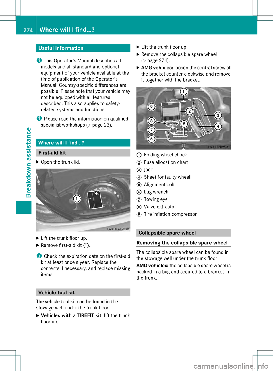
it together with the bracket. 0002
Folding wheel chock
0003 Fuse allocation chart
0023 Jack
0022 Shee tfor faulty wheel
0020 Alignmen tbolt
0021 Lug wrench
0014 Towing eye
0015 Valve extractor
0016 Tire inflation compressor Collapsible spare wheel
Removing the collapsible sparew heel The collapsible spare wheel can be found in
the stowage well unde
rthe trunk floor.
AMG vehicles: the collapsible spare wheel is
packed in a bag and secured to a bracket in
the trunk. 274
Where will I find...?Breakdown assistance
Page 277 of 334
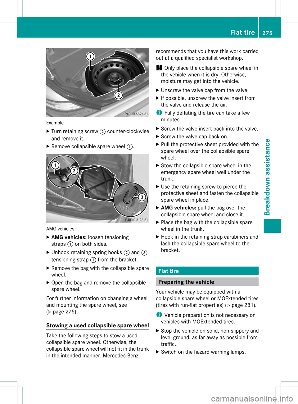
Example
X
Turn retaining screw 0003counter-clockwise
and remove it.
X Remove collapsible spare wheel 0002.AMG vehicles
X
AM Gvehicles: loosentensioning
straps 0002on both sides.
X Unhook retaining spring hooks 0003and 0023
tensioning strap 0002from the bracket.
X Remove the bag with the collapsible spare
wheel.
X Open the bag and remove the collapsible
spare wheel.
For further information on changing a wheel
and mounting the spare wheel, see
(Y page 275).
Stowing aused collapsible spare wheel Take the following steps to stow a used
collapsible spare wheel. Otherwise, the
collapsible spare wheel will not fit in the trunk
in the intended manner. Mercedes-Benz recommends that you have this work carried
out at a qualified specialist workshop.
!
Only place the collapsible spare wheel in
the vehicle when it is dry. Otherwise,
moisture may get into the vehicle.
X Unscrew the valve cap from the valve.
X If possible, unscrew the valve insert from
the valve and release the air.
i Fully deflating the tire can take a few
minutes.
X Screw the valve insert back into the valve.
X Screw the valve cap back on.
X Pull the protective sheet provided with the
spare wheel over the collapsible spare
wheel.
X Stow the collapsible spare wheel in the
emergency spare wheel well under the
trunk.
X Use the retaining screw to pierce the
protective sheet and fasten the collapsible
spare wheel in place.
X AMG vehicles: pull the bag over the
collapsible spare wheel and close it.
X Place the bag with the collapsible spare
wheel in the trunk.
X Hook in the retaining strap carabiners and
lash the collapsible spare wheel to the
bracket. Flat tire
Preparing the vehicle
Your vehicle may be equipped with a
collapsible spare wheel or MOExtended tires
(tires with run-flat properties) (Y page 281).
i Vehicle preparation is not necessary on
vehicles with MOExtended tires.
X Stop the vehicle on solid, non-slippery and
level ground, as far away as possible from
traffic.
X Switch on the hazard warning lamps. Flat tire
275Breakdown assistance