2012 MERCEDES-BENZ GL tow bar
[x] Cancel search: tow barPage 281 of 384
weight, even when accessories for the
crossbars (e.g. ski racks, bicycle racks, etc.)
are being used. Overloading the vehicle could
result in an accident. When calculating the
weight placed on the roof please make sure
to add the weight of the crossbars, accessory
racks and the load carried together.
Always adapt your driving style to the road,
traffic and weather conditions, and drive with
added caution when the roof is loaded.
Always drive with extreme care when the
carrier is loaded. Take into consideration that
when the carrier is loaded, the handling
characteristics are different from those when
operating the vehicle without a carrier loaded.GWARNING
Do not use accessories which have not been
approved by Mercedes-Benz for use in
conjunction with these crossbars. If non-
approved accessories are used, these
accessories and/or the objects attached to
them could come loose from the vehicle,
thereby injuring you and other persons and/
or causing damage to property, including
damage to your vehicle.
! Have a second person assist you when
installing the crossbars. Otherwise, the
vehicle could be damaged.
! Objects that are attached to crossbar
system accessories must not limit or
obstruct the movement of the sliding
sunroof. Otherwise, the tilt/sliding sunroof
could be damaged when it is raised.
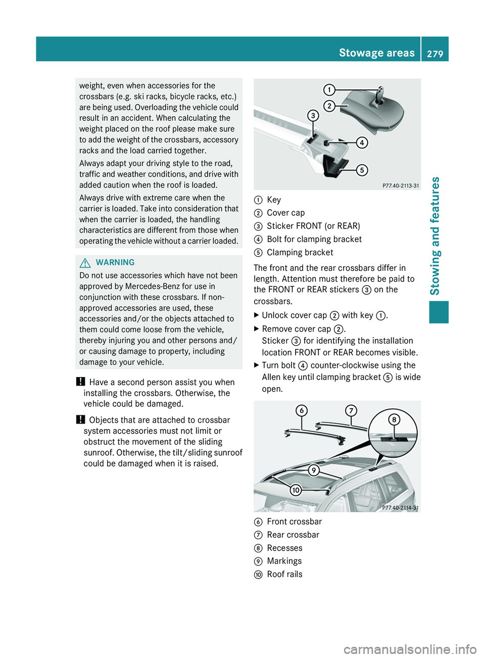
:Key;Cover cap=Sticker FRONT (or REAR)?Bolt for clamping bracketAClamping bracket
The front and the rear crossbars differ in
length. Attention must therefore be paid to
the FRONT or REAR stickers = on the
crossbars.
XUnlock cover cap ; with key :.XRemove cover cap ;.
Sticker = for identifying the installation
location FRONT or REAR becomes visible.XTurn bolt ? counter-clockwise using the
Allen key until clamping bracket A is wide
open.BFront crossbarCRear crossbarDRecessesEMarkingsFRoof railsStowage areas279Stowing and featuresZ
Page 282 of 384
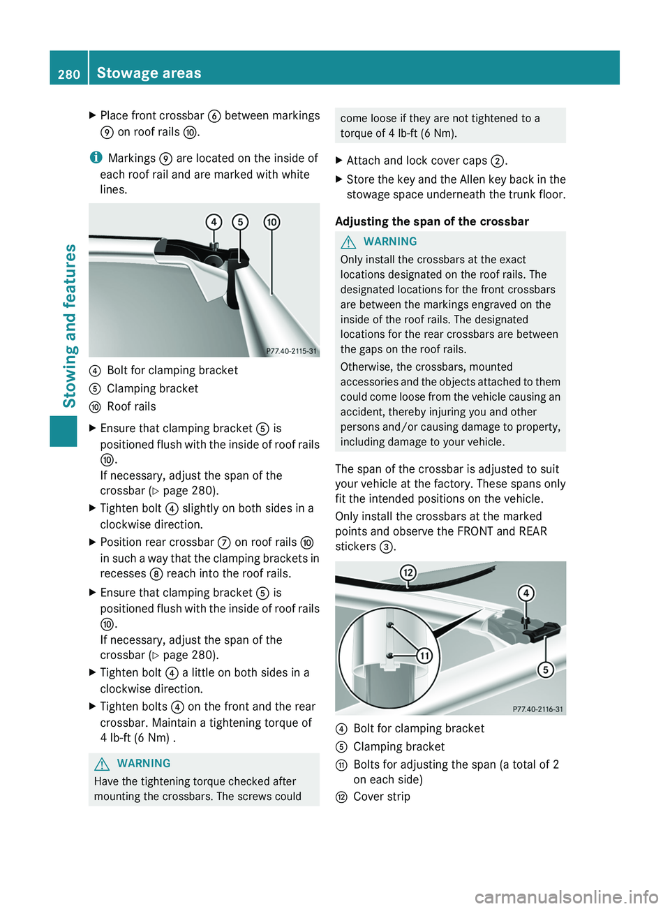
XPlace front crossbar B between markings
E on roof rails F.
i
Markings E are located on the inside of
each roof rail and are marked with white
lines.
?Bolt for clamping bracketAClamping bracketFRoof railsXEnsure that clamping bracket A is
positioned flush with the inside of roof rails
F .
If necessary, adjust the span of the
crossbar ( Y page 280).XTighten bolt ? slightly on both sides in a
clockwise direction.XPosition rear crossbar C on roof rails F
in such a way that the clamping brackets in
recesses D reach into the roof rails.XEnsure that clamping bracket A is
positioned flush with the inside of roof rails
F .
If necessary, adjust the span of the
crossbar ( Y page 280).XTighten bolt ? a little on both sides in a
clockwise direction.XTighten bolts ? on the front and the rear
crossbar. Maintain a tightening torque of
4 lb-ft (6 Nm) .GWARNING
Have the tightening torque checked after
mounting the crossbars. The screws could
come loose if they are not tightened to a
torque of 4 lb-ft (6 Nm).XAttach and lock cover caps ;.XStore the key and the Allen key back in the
stowage space underneath the trunk floor.
Adjusting the span of the crossbar
GWARNING
Only install the crossbars at the exact
locations designated on the roof rails. The
designated locations for the front crossbars
are between the markings engraved on the
inside of the roof rails. The designated
locations for the rear crossbars are between
the gaps on the roof rails.
Otherwise, the crossbars, mounted
accessories and the objects attached to them
could come loose from the vehicle causing an
accident, thereby injuring you and other
persons and/or causing damage to property,
including damage to your vehicle.
The span of the crossbar is adjusted to suit
your vehicle at the factory. These spans only
fit the intended positions on the vehicle.
Only install the crossbars at the marked
points and observe the FRONT and REAR
stickers =.
?Bolt for clamping bracketAClamping bracketGBolts for adjusting the span (a total of 2
on each side)HCover strip280Stowage areasStowing and features
Page 283 of 384
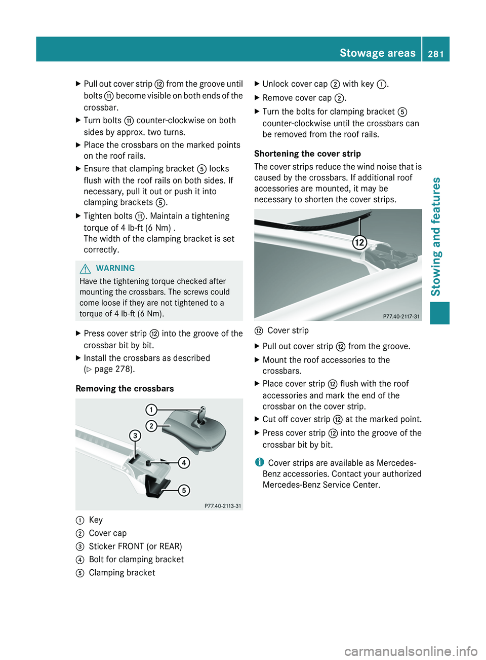
XPull out cover strip H from the groove until
bolts G become visible on both ends of the
crossbar.XTurn bolts G counter-clockwise on both
sides by approx. two turns.XPlace the crossbars on the marked points
on the roof rails.XEnsure that clamping bracket A locks
flush with the roof rails on both sides. If
necessary, pull it out or push it into
clamping brackets A.XTighten bolts G. Maintain a tightening
torque of 4 lb-ft (6 Nm) .
The width of the clamping bracket is set
correctly.GWARNING
Have the tightening torque checked after
mounting the crossbars. The screws could
come loose if they are not tightened to a
torque of 4 lb-ft (6 Nm).
XPress cover strip H into the groove of the
crossbar bit by bit.XInstall the crossbars as described
( Y page 278).
Removing the crossbars
:Key;Cover cap=Sticker FRONT (or REAR)?Bolt for clamping bracketAClamping bracketXUnlock cover cap ; with key :.XRemove cover cap ;.XTurn the bolts for clamping bracket A
counter-clockwise until the crossbars can
be removed from the roof rails.
Shortening the cover strip
The cover strips reduce the wind noise that is
caused by the crossbars. If additional roof
accessories are mounted, it may be
necessary to shorten the cover strips.
HCover stripXPull out cover strip H from the groove.XMount the roof accessories to the
crossbars.XPlace cover strip H flush with the roof
accessories and mark the end of the
crossbar on the cover strip.XCut off cover strip H at the marked point.XPress cover strip H into the groove of the
crossbar bit by bit.
i Cover strips are available as Mercedes-
Benz accessories. Contact your authorized
Mercedes-Benz Service Center.
Stowage areas281Stowing and featuresZ
Page 322 of 384
Tire pressure of 180 kPa (1.8 bar/
26 psi) is reachedXPress the on/off switch on the tire inflation
compressor to 0.
The tire inflation compressor is switched
off.XUnscrew the filler hose from the valve of
the faulty tire.
! After use, excess TIREFIT may run out of
the filler hose. This could cause stains.
Therefore, place the filler hose in the plastic
bag which contained the TIREFIT kit.
XStow the tire sealant bottle and the tire
inflation compressor.XPull away immediately .GWARNING
Do not exceed a vehicle speed of 50 mph
(80 km/h ). A TIREFIT repair is not designed to
operate at higher speeds.
The sticker must be attached on the
instrument cluster where it will be easily seen
by the driver.
Vehicle handling characteristics of a TIREFIT
repaired tire may change. Adapt your driving
accordingly.
XStop after driving for approximately ten
minutes and check the tire pressure with
the tire inflation compressor.GWARNING
If tire inflation pressure has fallen below
130 kPa (1.3 bar/26 psi) do not continue to
drive the vehicle.
Park your vehicle safely away from the
roadway and contact the nearest authorized
Mercedes-Benz Center or Roadside
Assistance.
Have the damaged tire replaced.
XCorrect the tire pressure if it is at least
130 kPa (1.3 bar/20 psi) (for the required
values, see the Tire and Loading
Information placard on the driver's sideB-pillar or the tire pressure table inside the
fuel filler flap).XTo increase the tire pressure: switch on
the tire inflation compressor.
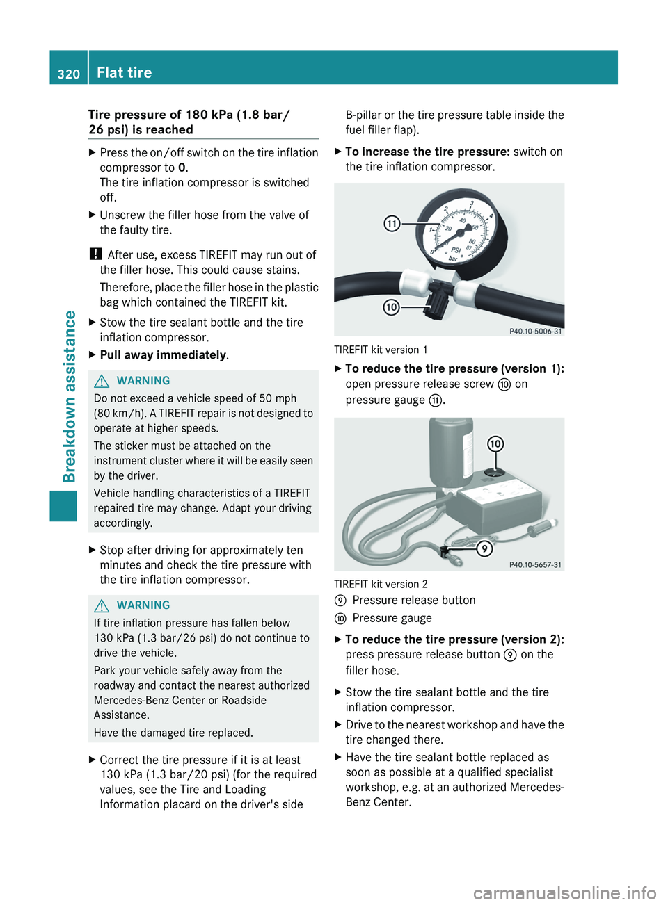
TIREFIT kit version 1
XTo reduce the tire pressure (version 1):
open pressure release screw F on
pressure gauge G.
TIREFIT kit version 2
EPressure release buttonFPressure gaugeXTo reduce the tire pressure (version 2):
press pressure release button E on the
filler hose.XStow the tire sealant bottle and the tire
inflation compressor.XDrive to the nearest workshop and have the
tire changed there.XHave the tire sealant bottle replaced as
soon as possible at a qualified specialist
workshop, e.g. at an authorized Mercedes-
Benz Center.320Flat tireBreakdown assistance
Page 333 of 384
Towing and tow-starting
Important safety notes
GWARNING
If you tow the vehicle, you must use a rigid
towing bar if:
R the engine is not running.
R there is a brake system malfunction.
R there is a malfunction in the power supply
or the vehicle's electrical system.
The power assistance for the steering and the
brake force booster do not work when the
engine is not running. You will need more
force to steer and brake, you may have to
depress the brake pedal with maximum force.
Before towing away, make sure that the
steering can be moved and is not locked.
If you tow or tow-start another vehicle, its
weight must not exceed the maximum
permissible gross vehicle weight of your
vehicle.
It is better to have the vehicle transported
than to have it towed.
! You may only tow the vehicle a maximum
distance of 30 miles (50 km). A towing
speed of 30 mph (50 km/h) must not be
exceeded.
For towing distances over 30 miles
(50 km), the vehicle must loaded onto a
transporter.
! Only secure the tow rope or tow bar at the
towing eyes. Otherwise, the vehicle could
be damaged.
! Do not use the towing eye for recovery,
as this could damage the vehicle. If in
doubt, recover the vehicle with a crane.
! When towing, pull away slowly and
smoothly. If the tractive power is too high,
the vehicles could be damaged.
! Do not tow with sling-type equipment.
This could damage the vehicle.
! When towing vehicles with KEYLESS-GO,
use the key instead of the Start/Stop
button. Otherwise, the automatic
transmission may shift to position P when
the driver's or front-passenger door are
opened, which could lead to damage to the
transmission.
! Vehicles with differential locks: make
sure that the differential locks are in
automatic mode. When towing, the
differential locks must not be switched on
by hand. This could otherwise damage the
transmission.
! Vehicles with 4MATIC must not be towed
with either the front or the rear axle raised,
as doing so will damage the transmission.
If the vehicle has suffered transmission
damage, have it transported on a transporter
or trailer.
The automatic transmission must be in
position N when the vehicle is being towed.
The battery must be connected and charged.
Otherwise, you:
R cannot turn the SmartKey to position 2 in
the ignition lock
R cannot shift the automatic transmission to
position N
i Before the vehicle is towed, switch off the
automatic locking feature ( Y page 226).
You could otherwise be locked out when
pushing or towing the vehicle.
Installing/removing the towing eye
Installing the towing eye
Vehicles with a trailer tow hitch: if possible
secure the towing device on the trailer tow
hitch ( Y page 210).
XRemove the towing eye from the vehicle
tool kit ( Y page 314).Towing and tow-starting331Breakdown assistanceZ
Page 363 of 384
Maximum load on one tire
Maximum load on one tire. This is calculated
by dividing the maximum axle load of one axle
by two.
PSI (pounds per square inch)
A standard unit of measure for tire pressure.
Aspect ratio
Relationship between tire height and tire
width in percent.
Tire pressure
This is pressure inside the tire applying an
outward force to each square inch of the tire's
surface. The tire pressure is specified in
pounds per square inch (psi), in kilopascal
(kPa) or in bar. The tire pressure should only
be corrected when the tires are cold. For this,
the vehicle must have been stationary for at
least three hours or not have traveled more
than 1.6 km (1 mile) in this time.
Tire pressure of cold tires
Tire pressure when the vehicle has been
stationary for at least three hours or not have
traveled more than 1.6 km (1 mile) in this
time.
Tread
The part of the tire that comes into contact
with the road.
Bead
The tire bead ensures that the tire sits
securely on the wheel. There are several steel
wires in the bead to prevent the tire from
coming loose from the wheel rim.
Sidewall
The part of the tire between the tread and the
bead.
Weight of optional extras
The combined weight of those optional extras
that weigh more than the replaced standard
part and more than 2.3 kilograms (5 lbs).
These optional extras, such as high-
performance brakes, level control, a roof rack
or a high-performance battery, are not
included in the curb weight and accessory
weight.
TIN (Tire Identification Number)
This is a unique identifier which can be used
by a tire manufacturer to identify tires, for
example for a product recall, and thus identify
the purchasers. The TIN is made up of the
manufacturer's identity code, tire size, tire
type code and the manufacturing date.
Load bearing index
The load bearing index (also load index) is a
code that contains the maximum load bearing
capacity of a tire.
Traction
Traction is the result of friction between the
tires and the road surface.
TWR (Tongue Weight Rating)
The TWR specifies the maximum permissible
weight that the ball coupling of the trailer tow
hitch can support.
Definition of terms for tires and loading361Wheels and tiresZ