2012 MERCEDES-BENZ E-CLASS ESTATE change time
[x] Cancel search: change timePage 266 of 457
heating adopts the THERMATIC or
THERMOTRONIC temperature setting.
You can switch off the auxiliary heating by
using the remote control or the auxiliary heat-
ing button on the centre console.
i Switch the auxiliary heating on regularly
once a month for about ten minutes.
Selecting the departure time or deactivat-
ing a selected departure time
X Press the =or; button on the steer-
ing wheel to select the Settings menu.
X Press the :or9 button to select the
Heating submenu.
X Press ato confirm.
You will see the selected setting.
X Press ato confirm.
X Press the :or9 button to select
one of the three departure times or Timeroff (no timer active).
X Press ato confirm.
If a departure time is selected, the yellow
indicator lamp lights up on the auxiliary
heating button.
Changing the departure time
X Press the =or; button on the steer-
ing wheel to select the Settings menu.
X Press the :or9 button to select the
Heating submenu.
X Press ato confirm.
You will see the selected setting.
X Press ato confirm.
X Press the :or9 button to select A ,
B or
Change C .
X Press ato confirm.
You can now change the departure time.
X Press the =or; button to select the
display to be changed: hours, minutes. X
Press the :or9 button to set the
selected display.
X Press the abutton to store the entry.
The yellow indicator lamp on the auxiliary
heating button lights up.
Convenience Activating/deactivating the EASY-
ENTRY/EXIT feature
G
WARNING
The steering wheel moves when the EASY-
ENTRY/EXIT feature is active. There is a risk
of occupants becoming trapped. Before acti-
vating the EASY-ENTRY/EXIT feature, make
sure that nobody can become trapped.
Do not leave children unsupervised in the
vehicle, even if they are secured in a child
restraint system. The children could open the
driver's door and thereby unintentionally acti-
vate the EASY-ENTRY/EXIT feature and
become trapped.
X Press the =or; button on the steer-
ing wheel to select the Settings menu.
X Press the :or9 button to select the
Convenience submenu.
X Press ato confirm.
X Press the :or9 button to select the
Easy Entry/Exit: function.
If the Easy Entry/Exit function is activa-
ted, the vehicle steering wheel is displayed
in red in the multifunction display.
X Press the abutton to save the setting.
Further information on the EASY-ENTRY/EXIT
feature (Y page 118).
Switching the belt adjustment on/off
X Press the =or; button on the steer-
ing wheel to select the Settings menu.
X Press the :or9 button to select the
Convenience submenu.
X Press ato confirm. Menus and submenus
263On-board computer and displays Z
Page 313 of 457
Useful information
i This Owner's Manual describes all mod-
els, series and optional equipment for your
vehicle that were available at the time of
going to press. National variations are pos-
sible. Note that your vehicle may not be
equipped with all of the functions descri-
bed. This is also the case for systems and
functions relevant to safety.
i Read the information on qualified special-
ist workshops: (Y page 25). Stowage areas
Loading guidelines
G
WARNING
Secure and position the load as described in
the loading guidelines.
Otherwise, vehicle occupants could
be injured by the load being thrown around in
the even tofsharp braking, a sudden change
in direction or an accident.
You will find further information in the "Secur-
ing a load" section.
Even if you follow all the loading guidelines,
the load will increase the risk of injury in the
event of an accident. G
WARNING
Keep the boot lid/tailgate closed while the
vehicle is in operation. Otherwise, exhaust
fumes could enter the vehicle interior and poi-
son you.
The handling characteristics of a laden vehi-
cle are dependent on the distribution of the
load within the vehicle. For this reason, you
should observe the following notes when
transporting a load:
R when transporting a load, never exceed the
maximum permissible gross vehicle weight or the permissible axle loads for the vehicle
(including occupants).
R position heavy loads as far forwards as pos-
sible and as low down in the boot/luggage
compartmenta s possible.
R the load must not protrude above the upper
edge of the seat backrests.
R always place the load against the rear or
front seat backrests. Make sure that the
seat backrests are securely locked into
place.
R always place the load behind unoccupied
seats if possible.
R secure the load with sufficiently strong and
wear-resistant lashing material. pad sharp
edges for protection.
i Load restraints are available at any quali-
fied specialist workshop, e.g. a Mercedes-
Benz Service Centre. Stowage compartments
Important safety notes G
WARNING
The stowage compartments must be closed
when items are stored in them. Luggage nets
are not designed to secure heavy items of
luggage.
You or other vehicle occupants could be
injured by objects being thrown around if you:
R brake sharply
R change direction suddenly
R are involved in an accident
Sharp-edged and fragile objects must not be
placed in the luggage net.
Do not place hard objects in the map pockets.
Objects must not protrude from the map
pockets. 310
Stowage areasStowing and features
Page 368 of 457
R
Immediately change out of clothing which
has come into contact with tyre sealant.
R If an allergic reaction occurs, seek medical
attention immediately.
! Do not operate the tyre inflation com-
pressor for longer than eight minutes at a
time withou tabreak. It may otherwise
overheat.
The tyre inflation compressor can be oper-
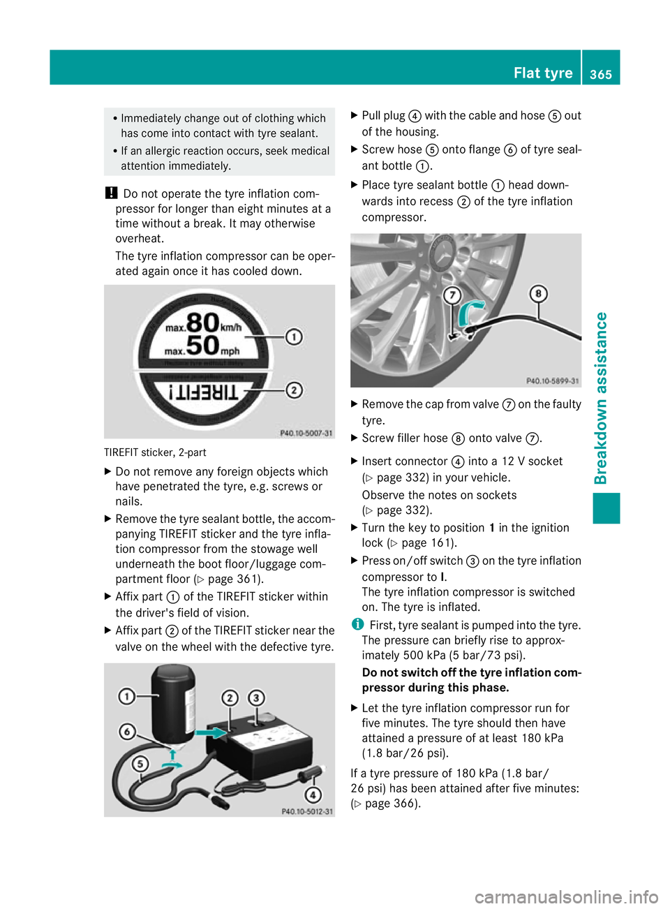
ated again once it has cooled down. TIREFIT sticker, 2-part
X
Do not remove any foreign objects which
have penetrated the tyre, e.g. screws or
nails.
X Remove the tyre sealant bottle, the accom-
panying TIREFIT sticker and the tyre infla-
tion compressor from the stowage well
underneath the boot floor/luggage com-
partment floor (Y page 361).
X Affix part :of the TIREFIT sticker within
the driver's field of vision.
X Affix part ;of the TIREFIT sticker near the
valve on the wheel with the defective tyre. X
Pull plug ?with the cable and hose Aout
of the housing.
X Screw hose Aonto flange Bof tyre seal-
ant bottle :.
X Place tyre sealant bottle :head down-
wards into recess ;of the tyre inflation
compressor. X
Remove the cap from valve Con the faulty
tyre.
X Screw filler hose Donto valve C.
X Insert connector ?into a 12 V socket
(Y page 332) in your vehicle.
Observe the notes on sockets
(Y page 332).
X Turn the key to position 1in the ignition
lock (Y page 161).
X Press on/off switch =on the tyre inflation
compressor to I.
The tyre inflation compressor is switched
on. The tyre is inflated.
i First, tyre sealant is pumped into the tyre.
The pressure can briefly rise to approx-
imately 500 kPa (5 bar/73 psi).
Do not switch off the tyre inflation com-
pressor during this phase.
X Let the tyre inflation compressor run for
five minutes. The tyre should then have
attained a pressure of at least 180 kPa
(1.8 bar/26 psi).
If a tyre pressure of 180 kPa (1.8 bar/
26 psi) has been attained after five minutes:
(Y page 366). Flat tyre
365Breakdown assistance Z
Page 388 of 457
Speeds up to 210 km/h(does not apply to
AMG vehicles): despite the values stated on
the tyre pressure information label (fuel filler
flap), for speeds up to 210 km/h andwith
R16 or R17 tyres, the values stated can be
reduced as follows without a reduction in
safety:
R Saloon: Ò30kPa (Ò0.3bar/Ò4psi)
R Estate: Ò20 kPa (Ò0.2 bar/Ò3p si)
This does not apply to vehicles towing a
trailer.
This improves the ride comfort of your vehi-
cle; however, the fuel consumption may
increase slightly. Tyre pressure loss warning system
Important safety notes While the vehicle is in motion, the tyre pres-
sure loss warning system monitors the set
tyre pressure using the rotational speed of
the wheels. This enables the system to detect
significant pressure loss in a tyre. If the speed
of rotation of a wheel changes as a result of
a loss of pressure, a corresponding warning
message will appearint he multifunction dis-
play.
The tyre pressure warning system does not
warn you of an incorrectly set tyre pressure.
Observe the notes on the recommended tyre
pressure (Y page 383).
The tyre pressure loss warning system does
not replace the need to regularly check your
vehicle's tyre pressures, since an even loss of
pressure on several tyres at the same time
cannot be detected by the tyre pressure loss
warning system.
The tyre pressure monitor is not able to warn
you of a sudden loss of pressure, e.g. if the
tyre is penetrated by a foreign object. In the
event of a sudden loss of pressure, bring the
vehicle to a halt by braking carefully. Avoid
abrupt steering manoeuvres. The function of the tyre pressure loss warning
system is limited or delayed if:
R snow chains are fitted to your vehicle's
tyres.
R road conditions are wintry.
R you are driving on sand or gravel.
R you adopt a very sporty driving style (cor-
nering at high speeds or driving with high
rates of acceleration).
R you are towing a very heavy or large trailer.
R you are driving with a heavy load (in the
vehicle or on the roof).
Restarting the tyre pressure loss warn-
ing system Restart the tyre pressure loss warning system
if you have:
R
changed the tyre pressure
R changed the wheels or tyres
R fitted new wheels or tyres
X Before restarting, make sure that the tyre
pressures are set properly on all four tyres
for the respective operating conditions.
The recommended tyre pressures can be
found in the table on the fuel filler flap. The
tyre pressure loss warning system can only
give reliable warnings if you have set the
correct tyre pressure. If an incorrect tyre
pressure is set, these incorrectv alues will
be monitored.
X Also observe the notes in the sectio non
tyre pressures (Y page 383).
X Make sure tha tthe key is in posi-
tion 2(Ypage 161) in the ignition lock.
X Press =or; on the steering wheel
to select the Serv.Serv. menu.
X Press the 9or: button to select
Tyre pressure .
X Press the abutton.
The message appears in the multifunction
display. Tyre pressure
385Wheels and tyres Z
Page 390 of 457
X
Press the 9or: button to select
Tyre pressure .
X Press the abutton.
The curren ttyre pressur efor each wheel
will be displayed in the multifunction dis-
play.
If the vehicle was parked for longer than
20 minutes the Tyre pressures will be displayed after a few minutes of
driving message is shown.
After a teach-in period, the tyre pressure
monitor automatically recognises new
wheels or new sensors. If a clear allocation of
the tyre pressure values to the individual
wheels is not possible, the message is shown
instead of the tyre pressure display .The tyre
pressures are already being monitored.
i If an emergency spare wheel is fitted, the
system may continue to show the tyre pres-
sure of the wheel that has been removed
for a few minutes. If this occurs, note that
the value displayed for the position where
the spare wheel is fitted is not the same as
the current tyre pressure of the emergency
spare wheel.
Warning messages of the tyre pressure
monitor If the tyre pressure monitor detects a signifi-
cant pressure loss on one or more tyres, a
warning message is shown in the multifunc-
tion display. Awarning tone also sounds and
the tyre pressure warning lamp lights up in
the instrument cluster.
Each tyre that is affected by a significant loss
of pressure is highlighted in the pressure dis-
play.
X If the Please correct tyre pressure message appears in the multifunction dis-
play, check the tyre pressure on all four
wheels and correct it if necessary.
i If the wheel positions on the vehicle are
interchanged, the tyre pressures may be
displayed for the wrong positions for a
short time. This is rectified after a few minutes of driving, and the tyre pressures
are displayed for the correct positions.
Restarting the tyre pressure monitor When you restar
tthe tyre pressure monitor,
all existing warning messages are deleted and
the warning lamps go out. The monitor uses
the currently set tyre pressures as the refer-
ence values for monitoring. In most cases, the
tyre pressure monitor will automatically
detect the new referencev alues after you
have changed the tyre pressure .However,
you can also define reference values man-
ually as described here. The tyre pressure
monitor then monitors the new tyre pressure
values.
X Use the table on the inside of the fuel filler
flap to ensure that the tyre pressure is set
correctly in all four tyres for the current
operating conditions.
Also observe the notes in the section on
tyre pressures (Y page 383).
X Make sure that the key is in position 2in
the ignition lock.
X Press the =or; button on the steer-
ing wheel to select the Serv. menu.
X Press the 9or: button to select
Tyre pressure .
X Press the abutton.
The multifunction display shows the cur-
rent tyre pressure for each tyre or the
Tyre pressures displayed after a few minutes of driving message.
X Press the :button.
The multifunction display shows the Use current pressure values as new ref‐
erence values message.
If you wish to confirm the restart:
X Press the abutton.
The Tyre press. monitor restarted message appears in the multifunction dis-
play. Tyre pressure
387Wheels and tyres Z
Page 392 of 457
Clean the contact surface
softhe wheel and
the brake disc thoroughly every time a wheel
is interchanged. Check the tyre pressure and,
if necessary, restart the tyre pressure loss
warning system or the tyre pressure monitor. Direction of rotation
Tyres with a specified direction of rotation
have additional benefits, e.g. if there is a risk
of aquaplaning. You will only gain these ben-
efits if the correct direction of rotation is
observed.
An arrow on the sidewall of the tyre indicates
its correct direction of rotation. Storing wheels
Store wheels that are not being used in a cool,
dry and preferably dark place. Protect the
tyres against oil, grease, petrol and diesel. Cleaning the wheels
G
WARNING
The water jet of circular-jet nozzles (dirt grind-
ers) can cause damage not visible from the
outside to tyres or chassis components. Com-
ponents damaged in this way can unexpect-
edly fail. There is a risk of an accident.
Do not use high-pressure cleaners with circu-
lar-jet nozzles to clean the vehicle. Have dam-
aged tyres or chassis components replaced
immediately. Fitting
awheel
Preparing the vehicle X
Stop the vehicle on solid, non-slippery and
level ground.
X Apply the parking brake.
X Bring the front wheels into the straight-
ahead position.
X Shift the transmission to position P.X
Vehicles with AIRMATIC :make sure that
"normal" level is selected (Y page 208).
X Switch off the engine.
X Vehicles without KEYLESS-GO: remove
the key from the ignition lock.
X Vehicles with KEYLESS-GO: open the
driver's door.
The on-board electronics have status 0,
which is the same as the key having been
removed.
X Vehicles with KEYLESS-GO: remove the
Start/Stop button from the ignition lock
(Y page 161).
X If included in the vehicle equipment,
remove the tyre-change tool kit from the
vehicle.
X Secure the vehicle to preven titfrom rolling
away.
i Apart from certain country-specific varia-
tions, the vehicles are not equipped with a
tyre-change tool kit. Some tools for chang-
ing a wheel are specific to the vehicle. For
more information on which tools are
required to perform a wheel change on your
vehicle, consult a qualified specialist work-
shop.
Necessary wheel-changing tools can
include, for example:
R jack
R wheel chock
R wheel wrench
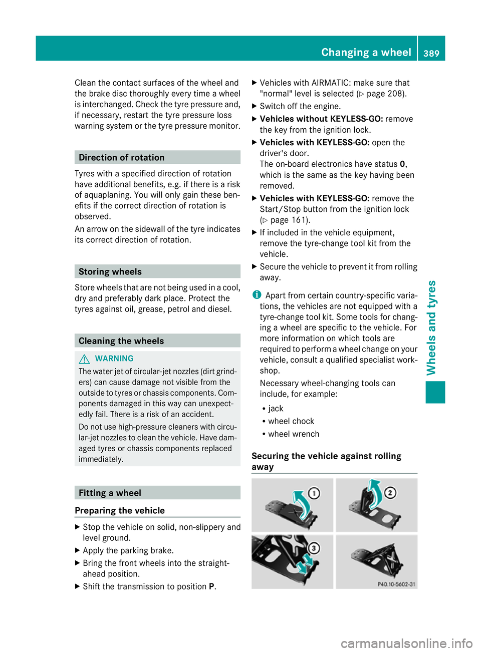
Securing the vehicle agains trolling
away Changing
awheel
389Wheels and tyres Z
Page 393 of 457
If yourv
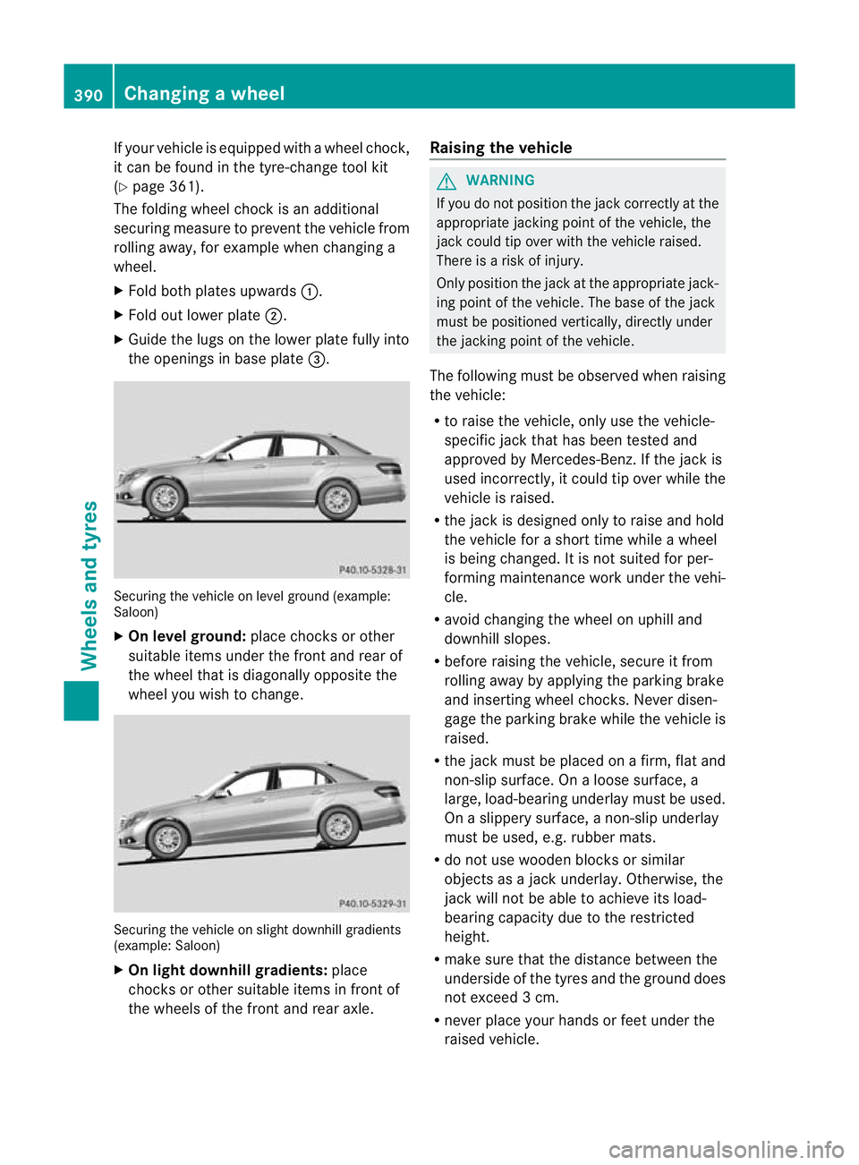
ehicle is equipped with a wheel chock,
it can be found in the tyre-change tool kit
(Y page 361).
The folding wheel choc kis an additional
securing measure to prevent the vehicle from
rolling away, for example when changing a
wheel.
X Fold both plates upwards :.
X Fold out lower plate ;.
X Guide the lugs on the lower plate fully into
the openings in base plate =.Securing the vehicle on level ground (example:
Saloon)
X
On level ground: place chocks or other
suitable items under the front and rear of
the wheel that is diagonally opposite the
wheel you wish to change. Securing the vehicle on slight downhill gradients
(example: Saloon)
X On light downhill gradients: place
chocks or other suitable items in front of
the wheels of the front and rear axle. Raising the vehicle G
WARNING
If you do not position the jack correctly at the
appropriate jacking point of the vehicle, the
jack could tip over with the vehicle raised.
There is a risk of injury.
Only position the jack at the appropriate jack-
ing point of the vehicle. The base of the jack
must be positioned vertically, directly under
the jacking point of the vehicle.
The following must be observed when raising
the vehicle:
R to raise the vehicle, only use the vehicle-
specific jack that has been tested and
approved by Mercedes-Benz. If the jack is
used incorrectly, it could tip over while the
vehicle is raised.
R the jack is designed only to raise and hold
the vehicle for a short time while a wheel
is being changed. It is not suited for per-
forming maintenance work under the vehi-
cle.
R avoid changing the wheel on uphill and
downhill slopes.
R before raising the vehicle, secure it from
rolling away by applying the parking brake
and inserting wheel chocks. Never disen-
gage the parking brake while the vehicle is
raised.
R the jack must be placed on a firm, flat and
non-slip surface. On a loose surface, a
large, load-bearing underlay must be used.
On a slippery surface, a non-slip underlay
must be used, e.g. rubber mats.
R do not use wooden blocks or similar
objects as a jack underlay.O therwise, the
jac kw ill not be able to achieve its load-
bearing capacity due to the restricted
height.
R make sure that the distance between the
underside of the tyres and the ground does
not exceed 3 cm.
R never place your hands or feet under the
raised vehicle. 390
Changing
awheelWheels and tyres
Page 442 of 457
a high sulphur conten
tis available, you will
need to carry out your vehicle's oil change
at shorter intervals. More information
aboutt he interval for oil change can be
obtained from any qualified specialist
workshop.
Usually you will find information about the
fuel grade on the pump. If you cannot find the
label on the petrol pump, ask the filling sta-
tion staff.
Information on refuelling (Y page 180).
Low outside temperatures
In winter months, diesel fuel with an improved
cold flow quality is available. In Europe, the
EN 590 standard defines various climate-
dependent temperature categories. Malfunc-
tions can be avoided by refuelling with diesel
fuel that corresponds to the climatic specifi-
cations outlined in EN 590. At unusually low
outside temperatures, it is possible that the
flow characteristics of the diesel fuel could be
insufficient .Accordingly, diesel fuel from
warmer areas may not be suitable for opera-
tion in colder climati cconditions.
i Further information on country-specific
fuel properties can be obtained from oil
companies, e.g. at filling stations.
Flow improvers
To improve the low-temperature resistance of
diesel fuel, a flow improver can be attached.
The effectiveness of a flow improver is not
guaranteed for every fuel.
Only use flow improvers tested and approved
by Mercedes-Benz. During use, please
observe the information on operation.
Correct dosage and sufficient mixing are deci-
sive in improving low-temperature resistance
with the flow improver. Overdosage can
potentially even decrease low-temperature
resistance and must therefore be avoided.
Follow the manufacturer's guidelines on dos-
age.
Mix the additive into the diesel in good time,
before the flow characteristics of the diesel become insufficient. Otherwise, malfunctions
can arise through heating the fuel system,
e.g. through parking in a heated garage.
More information about recommended flow
improvers can be obtained from any qualified
specialist workshop.
Fuel consumption information
H
Environmental note
CO 2(carbon dioxide) is the gas which scien-
tists believe to be principally responsible for
global warming (the greenhouse effect). Your
vehicle's CO 2emissions are directly related to
fuel consumption and therefore depend on:
R efficient use of the fuel by the engine
R driving style
R other non-technical factors, such as envi-
ronmental influences or road conditions
You can minimise your vehicle's CO 2emis-
sions by driving carefully and having it serv-
iced regularly.
The vehicle will use more fuel than usual in
the following situations:
R at very low outside temperatures
R in urban traffic
R on short journeys
R in mountainous terrain
R when towing a trailer
i Only for certain countries: you can find
the current consumption and emission val-
ues of your vehicle in the COC documents
(EU CERTIFICATE OF CONFORMITY). These
documents are delivered with your vehicle.
The consumption figures were in each case
based on the currently applicable version:
R for vehicles that comply with standards
up to and including the EURO 4standard,
in accordance with EU Directive
80/1268/EEC
R for vehicles tha tcomply with or exceed
the EURO 5standard, in accordance with
Regulation (EC )No. 715/2007 Service products and capacities
439Technical data Z