2012 MERCEDES-BENZ E-CLASS COUPE key battery
[x] Cancel search: key batteryPage 168 of 389
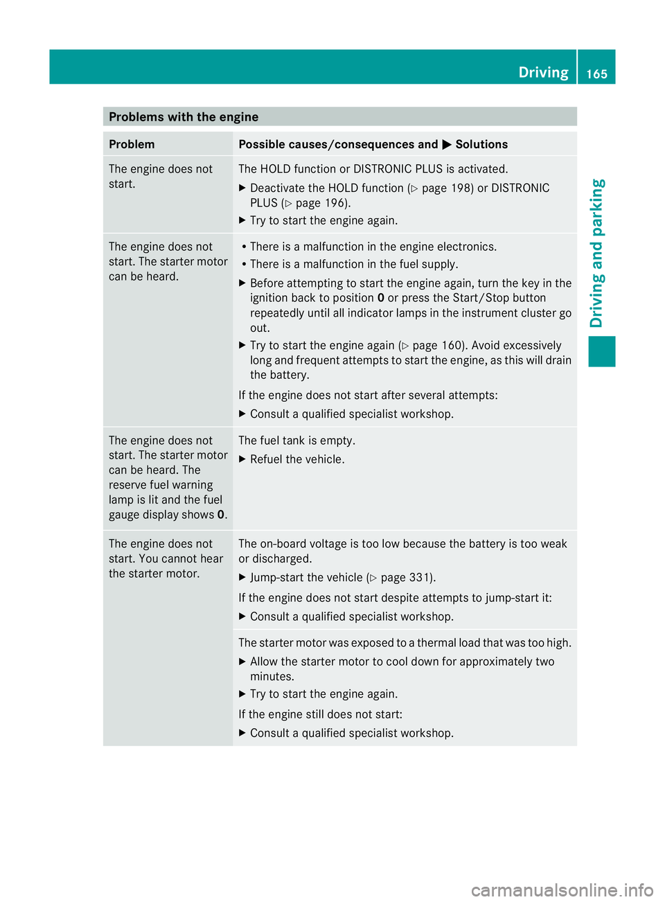
Problems with the engine
Problem Possible causes/consequences and
M Solutions
The engine does not
start. The HOLD function or DISTRONIC PLUS is activated.
X
Deactivate the HOLD function (Y page 198) or DISTRONIC
PLUS (Y page 196).
X Try to start the engine again. The engine does not
start. The starter motor
can be heard. R
There is a malfunction in the engine electronics.
R There is a malfunction in the fuel supply.
X Before attempting to start the engine again, turn the key in the
ignition back to position 0or press the Start/Stop button
repeatedly until all indicator lamps in the instrumen tcluster go
out.
X Try to start the engine again (Y page 160). Avoid excessively
long and frequent attempts to start the engine, as this will drain
the battery.
If the engine does not start after several attempts:
X Consult a qualified specialist workshop. The engine does not
start
.The starter motor
can be heard. The
reserve fuel warning
lamp is lit and the fuel
gauge display shows 0. The fuel tank is empty.
X
Refuel the vehicle. The engine does not
start. You cannot hear
the starter motor. The on-board voltage is too low because the battery is too weak
or discharged.
X
Jump-start the vehicle (Y page 331).
If the engine does not start despite attempts to jump-start it:
X Consult a qualified specialist workshop. The starter motor was exposed to a thermal load that was too high.
X Allow the starter motor to cool down for approximately two
minutes.
X Try to start the engine again.
If the engine still does not start:
X Consult a qualified specialist workshop. Driving
165Driving and parking Z
Page 180 of 389
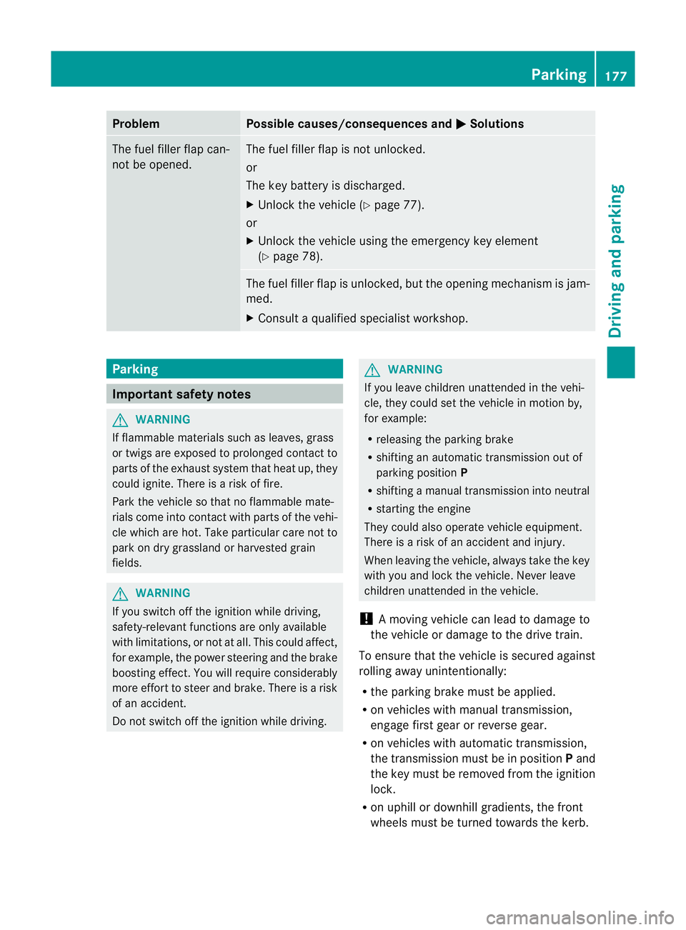
Problem Possible causes/consequences and
M Solutions
The fuel filler flap can-
not be opened. The fuel filler flap is not unlocked.
or
The key battery is discharged.
X
Unlock the vehicle (Y page 77).
or
X Unlock the vehicle using the emergency key element
(Y page 78). The fuel filler flap is unlocked, but the opening mechanism is jam-
med.
X
Consult a qualified specialist workshop. Parking
Important safety notes
G
WARNING
If flammable materials such as leaves, grass
or twigs are exposed to prolonged contact to
parts of the exhaust system that heat up, they
could ignite. There is a risk of fire.
Park the vehicle so that no flammable mate-
rials come into contact with parts of the vehi-
cle which are hot. Take particular care not to
park on dry grassland or harvested grain
fields. G
WARNING
If you switch off the ignition while driving,
safety-relevant functions are only available
with limitations, or not at all. This could affect,
for example, the power steering and the brake
boosting effect.Y ou will require considerably
more effort to steer and brake. There is a risk
of an accident.
Do not switch off the ignition while driving. G
WARNING
If you leave children unattended in the vehi-
cle, they could set the vehicle in motion by,
for example:
R releasing the parking brake
R shifting an automatic transmission out of
parking position P
R shifting a manual transmission into neutral
R starting the engine
They could also operate vehicle equipment.
There is a risk of an accident and injury.
When leaving the vehicle, always take the key
with you and lock the vehicle. Never leave
children unattended in the vehicle.
! Am oving vehicle can lead to damage to
the vehicle or damage to the drive train.
To ensure that the vehicle is secured against
rolling away unintentionally:
R the parking brake must be applied.
R on vehicles with manual transmission,
engage first gear or reverse gear.
R on vehicles with automatic transmission,
the transmission must be in position Pand
the key must be removed from the ignition
lock.
R on uphill or downhill gradients, the front
wheels must be turned towards the kerb. Parking
177Driving and parking Z
Page 227 of 389
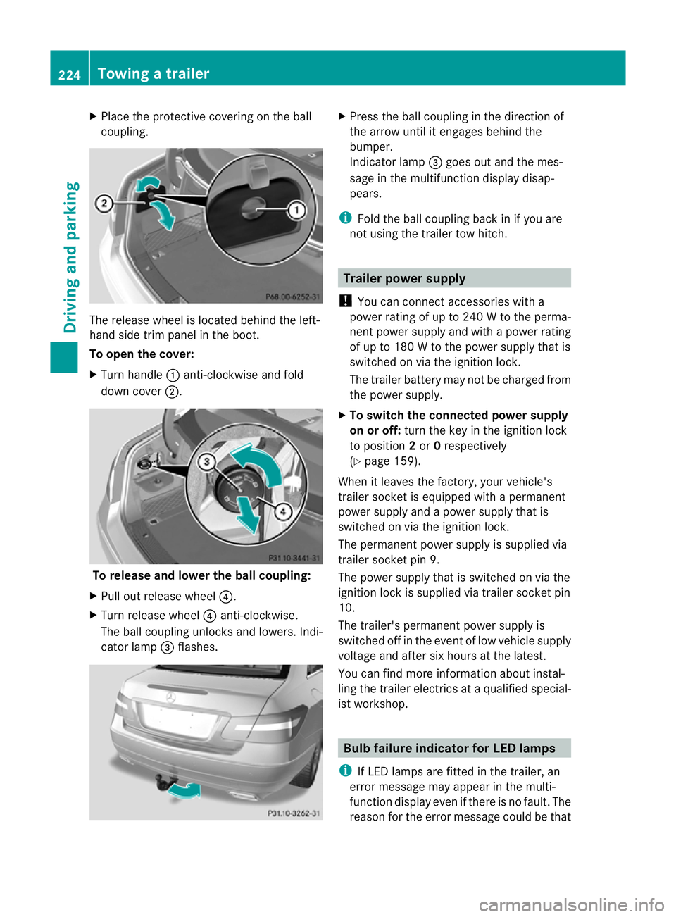
X
Place the protective covering on the ball
coupling. The release wheel is located behind the left-
hand side trim panel in the boot.
To open the cover:
X
Turn handle :anti-clockwise and fold
down cover ;. To release and lower the ball coupling:
X Pull out release wheel ?.
X Turn release wheel ?anti-clockwise.
The ball coupling unlocks and lowers. Indi-
cator lamp =flashes. X
Press the ball coupling in the direction of
the arrow until it engages behind the
bumper.
Indicator lamp =goes out and the mes-
sage in the multifunction display disap-
pears.
i Fold the ball coupling back in if you are
not using the trailer tow hitch. Trailer power supply
! You can connect accessories with a
power rating of up to 240 W to the perma-
nent power supply and with a power rating
of up to 180 W to the power supply that is
switched on via the ignition lock.
The trailer battery may not be charged from
the power supply.
X To switch the connected power supply
on or off: turn the key in the ignition lock
to position 2or 0respectively
(Y page 159).
When it leaves the factory, your vehicle's
trailer socket is equipped with a permanent
power supply and a power supply that is
switched on via the ignition lock.
The permanen tpower supply is supplied via
trailer socket pin 9.
The power supply that is switched on via the
ignition lock is supplied via trailer socket pin
10.
The trailer's permanent power supply is
switched off in the event of low vehicle supply
voltage and after six hours at the latest.
You can find more information about instal-
ling the trailer electric sataqualified special-
ist workshop. Bulb failure indicator for LED lamps
i If LED lamps are fitted in the trailer, an
error message may appear in the multi-
function display even if there is no fault. The
reason for the error message could be that 224
Towing
atrailerDriving an d parking
Page 298 of 389
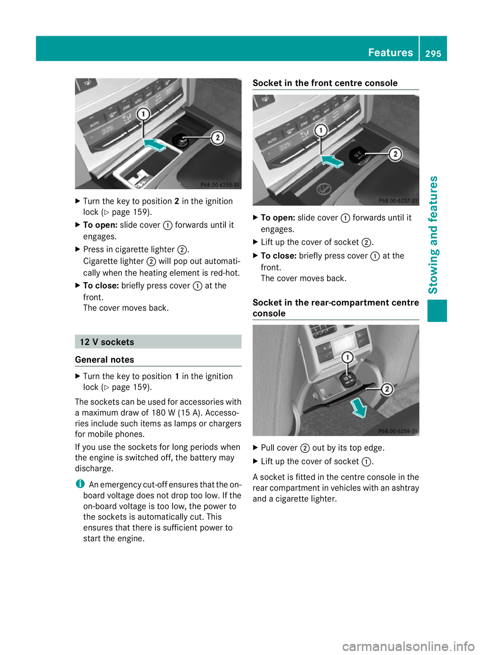
X
Turn the key to position 2in the ignition
lock (Y page 159).
X To open: slide cover :forwards until it
engages.
X Press in cigarette lighter ;.
Cigarette lighter ;will pop out automati-
cally when the heating element is red-hot.
X To close: briefly press cover :at the
front.
The cover moves back. 12
Vsockets
General notes X
Turn the key to position 1in the ignition
lock (Y page 159).
The sockets can be used for accessories with
a maximum draw of 180 W (15 A). Accesso-
ries include such items as lamps or chargers
for mobile phones.
If you use the sockets for long periods when
the engine is switched off ,the battery may
discharge.
i An emergency cut-offe nsures thatthe on-
board voltage does not drop too low. If the
on-board voltage is too low, the power to
the sockets is automatically cut. This
ensures that there is sufficient power to
start the engine. Socket in the front centre console
X
To open: slide cover :forwards until it
engages.
X Lift up the cover of socket ;.
X To close: briefly press cover :at the
front.
The cover moves back.
Socket in the rear-compartment centre
console X
Pull cover ;out by its top edge.
X Lift up the cover of socket :.
As ocket is fitted in the centre console in the
rear compartment in vehicles with an ashtray
and a cigarette lighter. Features
295Stowing and features Z
Page 332 of 389
G
WARNING
For safety reasons, Mercedes-Benz recom-
mends that you only use batteries which have
been tested and approved for yourv ehicle by
Mercedes-Benz .These batteries provide
increased impact protection to prevent vehi-
cle occupants from suffering acid burns
should the battery be damaged in the event
of an accident.
To prevent acid burns, observe the following
safety notes when handling batteries:
R do not lean over the battery.
R do not place any metal objects on a battery.
Otherwise, you could cause a short circuit
and the battery's gas mixture could ignite.
R make sure that you do not create an elec-
trostatic charge, e.g. by wearing synthetic
clothing or as a result of friction on fabrics.
Therefore, you should not pull or slide the
battery over carpets or other synthetic
materials.
R never touch the battery first. To discharge
a possible electrostatic charge, step out of
the vehicle first and touch the bodywork.
R do not wipe the battery using a cloth. The
battery may explode as a result of electro-
static charge or due to flying sparks. H
Environmental note Batteries contain pollutants.
It is illegal to dispose of them
with the household rubbish.
They must be collected sep-
arately and disposed of in an
environmentally responsible
recycling system.
Dispose of batteries in an
environmentally responsible
manner. Take discharged
batteries to a qualified spe-
cialist workshop or to a col-
lection point for used batter-
ies.
! Have the battery checked regularly at a
qualified specialist workshop. Observe the service intervals in the Service
Booklet or contact a qualified specialist
workshop for more information.
! You should have all work involving the
battery carried out at aqualified specialist
workshop. In the exceptional case that it is
necessary for you to disconnect the battery
yourself, make sure that:
R you switch off the engine and remove the
key. On vehicles with KEYLESS-GO,
ensure that the ignition is switched off.
Chec kthat all the indicator lamps in the
instrument cluster are off. Otherwise,
electronic components, such as the
alternator, may be damaged.
R you first remove the negative terminal
clamp and then the positive terminal
clamp. Never swap the terminal clamps.
Otherwise, the vehicle's electronic sys-
tem may be damaged.
R in vehicles with automatic transmission,
the transmission is locked in position P
after disconnecting the battery. The vehi-
cle is secured against rolling away.Y ou
can then no longer move the vehicle.
The battery and the cover of the positive
terminal clamp must be fitted securely dur-
ing operation.
In order for the battery to achieve the maxi-
mum possible service life, it must always be
sufficiently charged.
The vehicle battery, like other batteries, can
discharge over time if you do not use the
vehicle. In such cases, have the battery dis-
connected at a qualified specialist workshop.
You can also charge the battery with a
charger recommended by Mercedes-Benz.
For more information, please contact a quali-
fied specialist workshop.
Have the battery charge checked more fre-
quently if you use the vehicle mainly for short
trips or if you leave it standing idle for a
lengthy period. Consult a qualified specialist
workshop if you wish to leave your vehicle
parked up for a long period of time. Battery (vehicle)
329Breakdown assistance Z
Page 333 of 389
i
When you park the vehicle, remove the
key if you do not require any electrical con-
sumers. The vehicle will then use very little
energy, thus conserving battery power.
i After an interruption of the power supply,
e.g. the battery was discharged, you have
to:
R set the clock. Information on setting the
clock can be found in the separate oper-
ating instructions.
On vehicles with COMAND Online and a
navigation system, the clock is set auto-
matically.
R reset the function for folding the exterior
mirrors in/out automatically, by folding
the mirrors out once (Y page 118).Charging the battery
G
WARNING
Only charge the battery in a well-ventilated
area. As the battery is being charged, gases
can escape and generate minor explosions.
This could injure you and other persons or
cause damage to the paintwork or acid cor-
rosion on the vehicle.
You can obtain information on battery charg-
ers which allow the batter yto be charged
while still installed from a qualified specialist
workshop. G
WARNING
There is a risk of acid burns during the charg-
ing process due to the gases which escape
from the battery. Do not lean over the battery
during the charging process. G
WARNING
Battery acid is caustic. Avoid contact with the
skin, eyes or clothing.
! Only charge the installed battery with a
battery charger which has been tested and
approved by Mercedes-Benz. These battery chargers allow the battery to be charged
while still installed in the vehicle.
! Only use battery chargers with a maxi-
mum charging voltage of 14.8 V.
! Only charge the battery using the jump-
start connection point.
The jump-starting connection point is in the
engine compartment (Y page 331).
Read the battery charger's operating instruc-
tions before charging the battery.
X Open the bonnet (Y page 307).
X Connect the battery charger to the positive
terminal and earth point in the same order
as when connecting the donor battery in
the jump-starting procedure
(Y page 331). 330
Battery (vehicle)Breakdown assistance
Page 337 of 389
The battery must be connected and charged.
Otherwise, you:
R cannot turn the key in the ignition lock to
position 2
R cannot shift the transmission to position
N on vehicles with automatic transmission
Vehicles with automatic transmission:
release the selector lever lock manually to
move it out of position P(Y page 173).
i Deactivate the automatic locking feature
(Y page 84). You could otherwise be locked
out when pushing or towing the vehicle.
Deactivate tow-away protection
(Y page 71) before the vehicle is towed. Fitting/removing the towing eye
Fitting the towing eye G
WARNING
The exhaust tail pipe may be hot. You could
burn yourself if you touch the tail pipe. Be
particularly careful when removing the rear
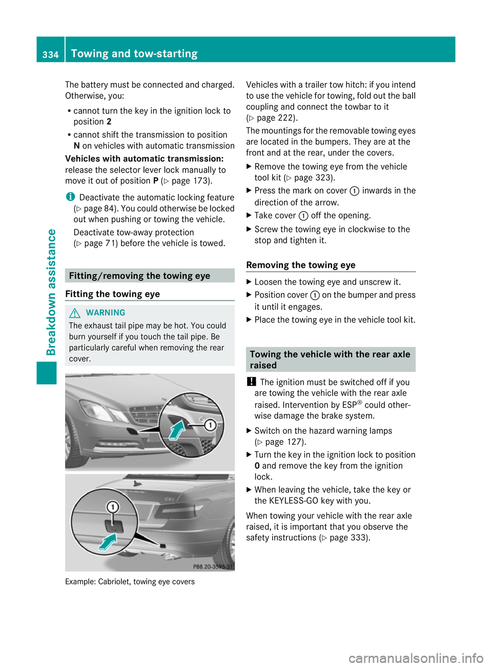
cover. Example: Cabriolet, towing eye covers Vehicles with a trailer tow hitch: if you intend
to use the vehicle for towing, fold out the ball
coupling and connect the towbar to it
(Y
page 222).
The mountings for the removable towing eyes
are located in the bumpers. They are at the
front and at the rear, under the covers.
X Remove the towing eye from the vehicle
tool kit (Y page 323).
X Press the mark on cover :inwards in the
direction of the arrow.
X Take cover :off the opening.
X Screw the towing eye in clockwise to the
stop and tighten it.
Removing the towing eye X
Loosen the towing eye and unscrew it.
X Position cover :on the bumper and press
it until it engages.
X Place the towing eye in the vehicle tool kit. Towing the vehicle with the rear axle
raised
! The ignition must be switched off if you
are towing the vehicle with the rear axle
raised. Intervention by ESP ®
could other-
wise damage the brake system.
X Switch on the hazard warning lamps
(Y page 127).
X Turn the key in the ignition lock to position
0 and remove the key from the ignition
lock.
X When leaving the vehicle, take the key or
the KEYLESS-GO key with you.
When towing your vehicle with the rear axle
raised, it is importan tthat you observe the
safety instructions (Y page 333).334
Towing and tow-startingBreakdown assistance
Page 339 of 389

X
Release the clutch pedal slowly; do not
depress the accelerato rpedal while doing
so.
The engine is started.
X Depress the clutch pedal and shift to neu-
tral.
X Stop at a suitable place.
X Depress the parking brake.
X Remove the rigid towing bar or towing rope.
X Remove the towing eye (Y page 334).
X Switch off the hazard warning lamps.
Before tow-starting the following conditions
must be fulfilled:
R the battery is connected.
R the engine has cooled down.
R the exhaust system has cooled down.
You can find information on "Jump-starting"
at (Y page 331). Electrical fuses
Important safety notes
G
WARNING
Only use fuses that have been approved for
Mercedes-Benz vehicles and which have the
correct fuse rating for the systems con-
cerned. Do not attempt to repair or bridge
faulty fuses. Using fuses which have not been
approved or attempting to repair or bridge
faulty fuses could cause the fuse to be over-
loaded and result in a fire. Have the cause
traced and rectified at a qualified specialist
workshop.
! Only use fuses that have been approved
for Mercedes-Benzv ehicles and which
have the correct fuse rating for the system
concerned. Otherwise, components or sys-
tems could be damaged.
The fuses in your vehicle serve to close down
faulty circuits. If afuse blows, all the compo-
nents on the circuit and their functions stop
operating. Blown fuses must be replace
dwith fuses of
the same rating, which you can recognise by
the colour and fuse rating. The fuse ratings
are listed in the fuse allocation chart.
If the newly inserted fuse also blows, have the
cause traced and rectified at a qualified spe-
cialist workshop, e.g. a Mercedes-Benz
Service Centre. Before replacing a fuse
X Secure the vehicle against rolling away
(Y page 177).
X Switch off all electrical consumers.
X Turn the key to position 0in the ignition
lock and remove it (Y page 159).
or
X On vehicles with KEYLESS-GO, make sure
the ignition is switched off (Y page 159).
All indicator lamps in the instrumen tcluster
must be off.
The fuses are located in various fuse boxes:
R fuse box on the driver's side of the dash-
board
R fuse box in the engine compartmen tonthe
left-hand side of the vehicle, when viewed
in the direction of travel
R fuse box in the boot on the right-hand side
of the vehicle, when viewed in the direction
of travel
The fuse allocation chart is located in the
vehicle tool kit in the stowage compartment
under the boot floor (Y page 323). Dashboard fuse box
! Do not use a pointed object such as a
screwdriver to open the cover in the dash-
board. You could damage the dashboard or
the cover.
! Make sure that no moisture can enter the
fuse box when the cover is open. 336
Electrical fusesBreakdown assistance