2012 MERCEDES-BENZ CLS SHOOTING BRAKE clock
[x] Cancel search: clockPage 139 of 405
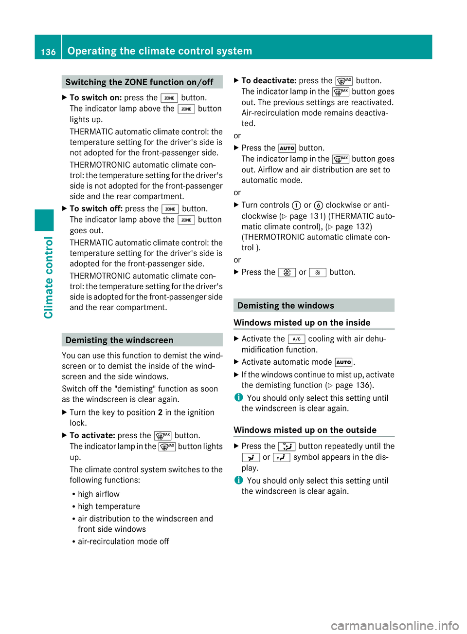
Switching the ZONE function on/off
X To switch on: press theábutton.
The indicator lamp above the ábutton
lights up.
THERMATIC automatic climate control: the
temperature setting for the driver's side is
not adopted for the front-passenger side.
THERMOTRONIC automatic climate con-
trol: the temperature setting for the driver's
side is not adopted for the front-passenger
side and the rear compartment.
X To switch off: press theábutton.
The indicator lamp above the ábutton
goes out.
THERMATIC automatic climate control: the
temperature setting for the driver's side is
adopted for the front-passenger side.
THERMOTRONIC automatic climate con-
trol: the temperature setting for the driver's
side is adopted for the front-passenger side
and the rear compartment. Demisting the windscreen
You can use this function to demist the wind-
screen or to demist the inside of the wind-
screen and the side windows.
Switch off the "demisting" function as soon
as the windscreen is clear again.
X Turn the key to position 2in the ignition
lock.
X To activate: press the¬button.
The indicator lamp in the ¬button lights
up.
The climate control system switches to the
following functions:
R high airflow
R high temperature
R air distribution to the windscreen and
front side windows
R air-recirculation mode off X
To deactivate: press the¬button.
The indicator lamp in the ¬button goes
out. The previous settings are reactivated.
Air-recirculation mode remains deactiva-
ted.
or
X Press the Ãbutton.
The indicator lamp in the ¬button goes
out. Airflow and air distribution are set to
automatic mode.
or
X Turn controls :orB clockwise or anti-
clockwise (Y page 131) (THERMATIC auto-
matic climate control), (Y page 132)
(THERMOTRONIC automatic climate con-
trol ).
or
X Press the KorI button. Demisting the windows
Windows misted up on the inside X
Activate the ¿cooling with air dehu-
midification function.
X Activate automatic mode Ã.
X If the windows continue to mist up, activate
the demisting function (Y page 136).
i You should only select this setting until
the windscreen is clear again.
Windows misted up on the outside X
Press the _button repeatedly until the
P orO symbol appears in the dis-
play.
i You should only select this setting until
the windscreen is clear again. 136
Operating the climate control systemClimate control
Page 146 of 405
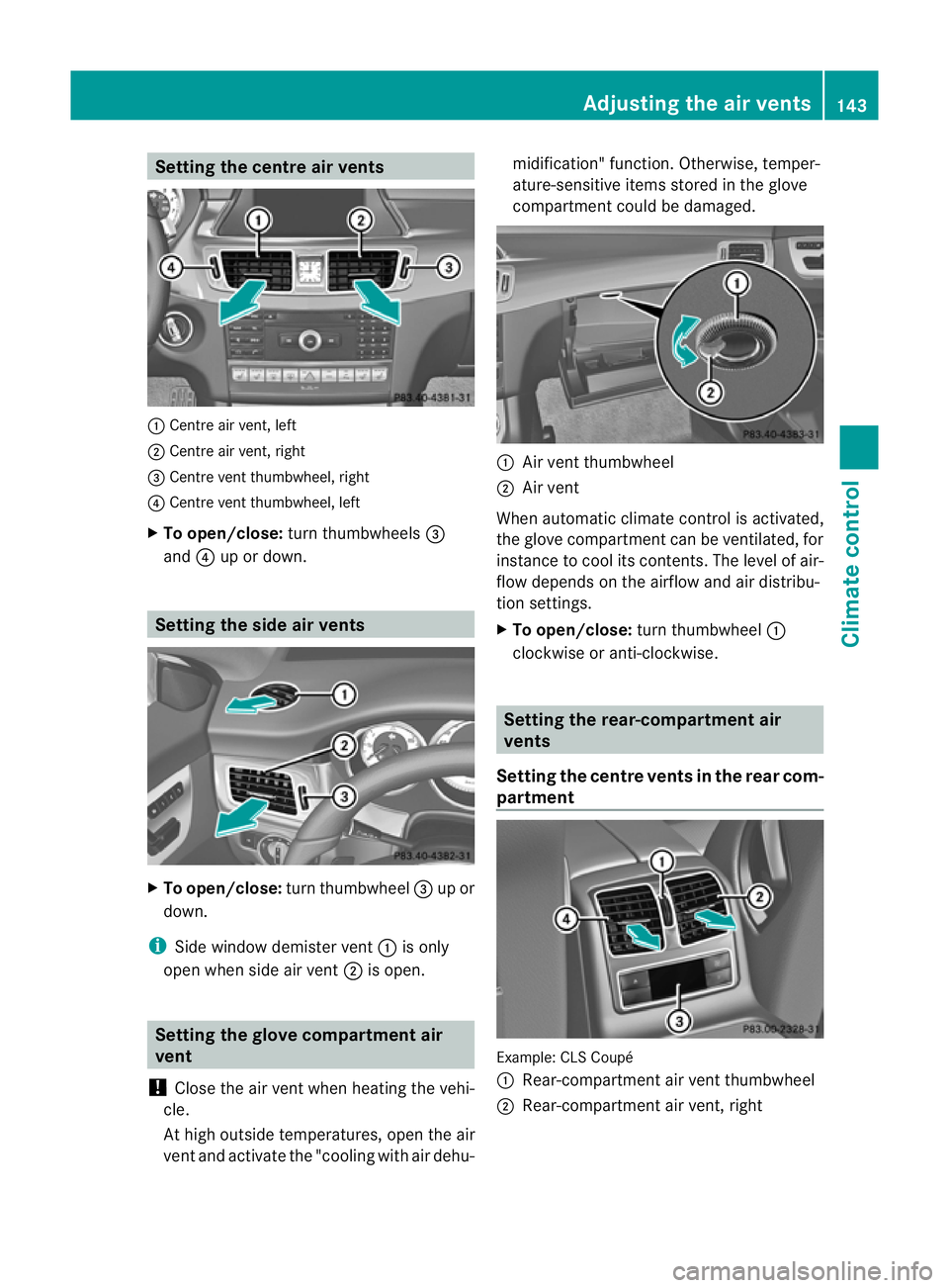
Setting the centre air vents
:
Centre air vent, left
; Centre air vent, right
= Centre vent thumbwheel, right
? Centre vent thumbwheel, left
X To open/close: turn thumbwheels =
and ?up or down. Setting the side air vents
X
To open/close: turn thumbwheel =up or
down.
i Side window demister vent :is only
open when side air vent ;is open. Setting the glove compartment air
vent
! Close the air vent when heating the vehi-
cle.
At high outside temperatures, open the air
vent and activate the "cooling with air dehu- midification" function. Otherwise, temper-
ature-sensitive items stored in the glove
compartmen
tcould be damaged. :
Air vent thumbwheel
; Air vent
When automatic climate control is activated,
the glove compartment can be ventilated, for
instance to cool its contents.T he level of air-
flow depends on the airflow and air distribu-
tion settings.
X To open/close: turn thumbwheel :
clockwise or anti-clockwise. Setting the rear-compartment air
vents
Setting the centre vents in the rear com-
partment Example: CLS Coupé
:
Rear-compartment air vent thumbwheel
; Rear-compartment air vent, right Adjusting the air vents
143Climate control Z
Page 165 of 405
G
WARNING
Electrostatic charge can lead to the creation
of sparks and to fuel vapours igniting. There
is a risk of fire and explosion.
Touch the vehicle bodywork just before open-
ing the fuel filler cap. This will discharge a
possible electrostatic charge.
! Do not use petrol to refuel vehicles with a
diesel engine. Do not use diesel to refuel
vehicles with a petrol engine. Do not switch
on the ignitio nifyou accidentally refuel
with the wrong fuel. Otherwise, the fuel will
enter the fuel system. Even small amounts
of the wrong fuel could result in damage to
the fuel system and the engine. The repair
costs are high. Notify aqualified specialist
workshop and have the fuel tan kand fuel
lines drained completely.
! Overfilling the fuel tank could damage the
fuel system.
! Take care not to spill any fuel on painted
surfaces .You could otherwise damage the
paintwork.
! Use a filter when adding fuel from a fuel
can. The fuel lines and/or the diesel injec-
tion system could otherwise be blocked by
particles from the fuel can.
If you overfill the fuel tank, fuel may spray out
when the fuel pump nozzle is removed.
Further information on fuel and on fuel grades
can be found in the "Fuel" section
(Y page 386). Refuelling
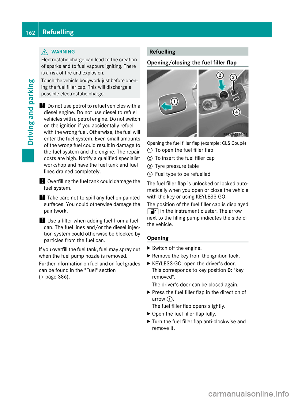
Opening/closing the fuel filler flap Opening the fuel filler flap (example: CLS Coupé)
:
To open the fuel filler flap
; To insert the fuel filler cap
= Tyre pressure table
? Fuel type to be refuelled
The fuel filler flap is unlocked or locked auto-
matically when you open or close the vehicle
with the key or using KEYLESS-GO.
The position of the fuel filler cap is displayed
8 in the instrument cluster. The arrow
next to the filling pump indicates the side of
the vehicle.
Opening X
Switch off the engine.
X Remove the key from the ignition lock.
X KEYLESS-GO: open the driver's door.
This corresponds to key position 0: "key
removed".
The driver's door can be closed again.
X Press the fuel filler flap in the direction of
arrow :.
The fuel filler flap opens slightly.
X Open the fuel filler flap fully.
X Turn the fuel filler flap anti-clockwise and
remove it. 162
RefuellingDriving and parking
Page 166 of 405
X
CLS Coupé: insert the fuel fille rcap into
the holde ronthe inside of fuel filler
flap ;.
or
X CLS Shooting Brake: insert the fuel filler
cap, held in a horizontal position, in the
recesses in the fuel filler flap hinge arm
from above.
X Completely insert the filler neck of the fuel
pump nozzle into the tank and refuel.
X Only fill the tank until the pump nozzle
switches off.
i Do not add any more fuel after the pump
stops filling for the first time. Otherwise,
fuel may leak out.
Closing X
Replace the cap on the filler neck and turn
clockwise until it engages audibly.
X Close the fuel filler flap.
i Close the fuel filler flap before locking the
vehicle. Otherwise, the locking pin of the
central locking prevents the fuel filler flap
from closing. Fuel filler flap emergency release
X CLS Coupé: open the boot lid. X
Slide the luggage net down.
X Open the right-hand side trim panel.
X Remove the first-aid kit (Y page 334).X
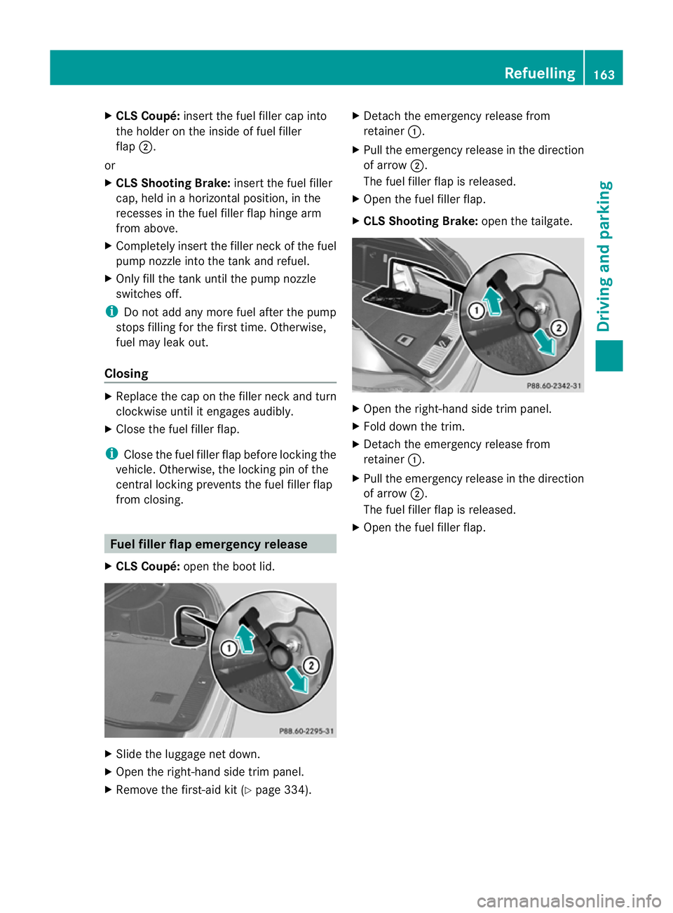
Detach the emergency release from
retainer :.
X Pull the emergency release in the direction
of arrow ;.
The fuel filler flap is released.
X Open the fuel filler flap.
X CLS Shooting Brake: open the tailgate. X
Open the right-hand side trim panel.
X Fold down the trim.
X Detach the emergency release from
retainer :.
X Pull the emergency release in the direction
of arrow ;.
The fuel filler flap is released.
X Open the fuel filler flap. Refuelling
163Driving and parking Z
Page 190 of 405
R
you depress the brake pedal again with a
certain amount of pressur euntil ë dis-
appears from the multifunctio ndisplay.
R you activate DISTRONIC PLUS.
When the HOLD function is activated, the
transmission is shifted automatically to posi-
tion Pif:
R the driver's door is open and the driver's
seat belt is unfastened.
R the engine is switched off, unless it is auto-
matically switched off by the ECO start/
stop function.
R the bonnet is opened.
R a system fault occurs.
R the power supply is not sufficient. RACE START
Important safety notes G
WARNING
RACE START is only available when SPORT
handling mode is activated. SPORT handling
mode will only be able to stabilise the vehicle
to a limited degree if the vehicle starts to skid
or a wheel starts to spin .The vehicle is there-
fore harder to control at the threshold range.
You could lose control of the vehicle and
cause an accident.
RACE START should only be used on closed
off circuits. Always adapt your driving style to
suit the prevailing road and weather condi-
tions.
i RACE START is only available in AMG vehi-
cles.
RACE START enables optimum acceleration
from a standing start. The precondition for
this is a suitable high-grip road surface. Activation conditions You can activate RACE START if:
R
the doors are closed.
R the engine is running and it has reached an
operating temperature of approximately
80 †. This is the case when the engine oil
temperature in the multifunction display
stops flashing.
R SPORT handling mode is activated
(Y page 68).
R the steering wheel is in the straight-ahead
position.
R the vehicle is stationary and the brake
pedal is depressed (left foot).
R the transmission is in position D.
Activating RACE START X
Depress the brake pedal with your left foot
and keep it depressed.
X Turn the drive program selector clockwise
(Y page 158) until the RSlamp lights up.
The Confirm RACE START: Cancel Pad‐
dle UP: Paddle DOWN message appears
in the multifunction display.
i If the activation conditions are no longer
fulfilled, RACE START is cancelled. The
RACE START cancelled message appears
in the multifunction display.
X To cancel: pull the left steering wheel shift
paddle (Y page 158).
or
X To confirm:p ull the right steering wheel
shif tpaddle (Y page 158).
The RACE START available Depress accelerator message appears in the mul-
tifunctio ndisplay.
i If you do not depress the accelerator
pedal fully within two seconds, RACE
START is cancelled. The RACE START not
possible See Owner's Manual message
appears in the multifunction display. Driving systems
187Driving and parking Z
Page 223 of 405
R
Maintain a greater distance from the vehi-
cle in front than when driving without a
trailer.
R Avoid braking abruptly. If possible, brake
gently at first to allow the trailer to run on.
Then, increase the braking force rapidly.
R The values given for gradient-climbing
capabilities from a standstill refer to sea
level. When driving in mountainous areas,
note that the power output of the engine,
and consequently the vehicle's gradient-
climbing capability, decrease with increas-
ing altitude. Folding out the ball coupling
G
WARNING
If the ball coupling is not correctly engaged,
the trailer can detach. There is a risk of an
accident.
Always engage the ball coupling as described. G
WARNING
If you release the ball coupling or it does not
engage correctly when folding in, it will swing
out. Within pivoting range of the ball coupling,
there is an increased risk of an accident and
injury.
Only release the ball coupling if the pivoting
range is unobstructed. Always make sure that
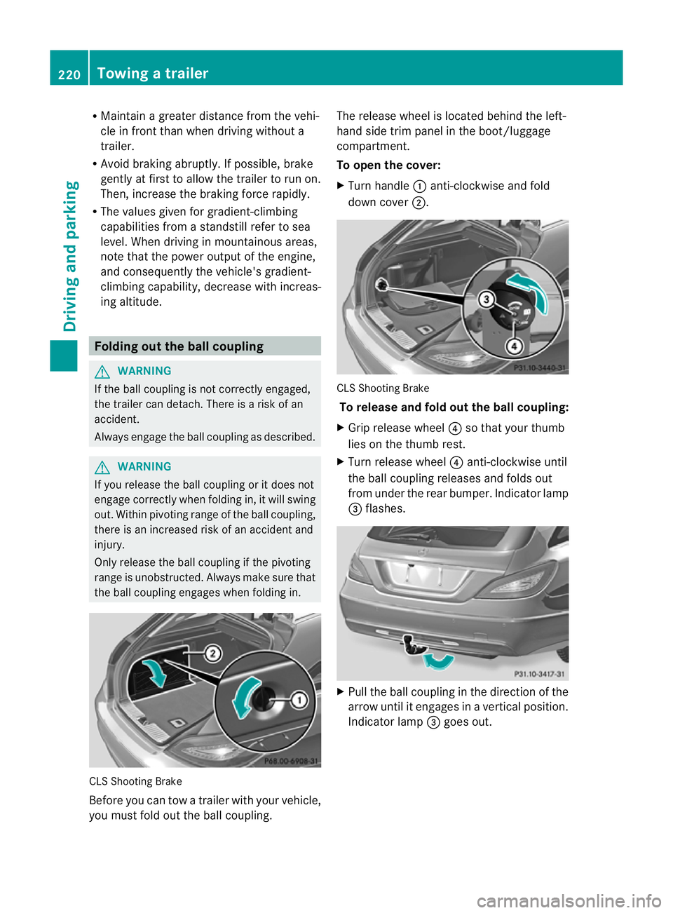
the ball coupling engages when folding in. CLS Shooting Brake
Before you can tow a trailer with your vehicle,
you must fold out the ball coupling. The release wheel is located behind the left-
hand side trim panel in the boot/luggage
compartment.
To open the cover:
X
Turn handle :anti-clockwise and fold
down cover ;. CLS Shooting Brake
To release and fold out the ball coupling:
X Grip release wheel ?so that your thumb
lies on the thumb rest.
X Turn release wheel ?anti-clockwise until
the ball coupling releases and folds out
from under the rear bumper. Indicator lamp
= flashes. X
Pull the ball coupling in the direction of the
arrow until it engages in a vertical position.
Indicator lamp =goes out. 220
Towing
atrailerDriving an d parking
Page 225 of 405
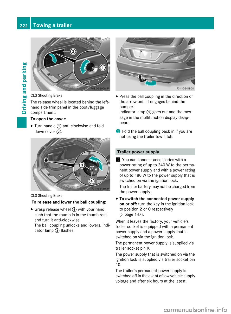
CLS Shooting Brake
The release wheel is located behind the left-
hand side trim panel in the boot/luggage
compartment.
To open the cover:
X
Turn handle :anti-clockwise and fold
down cover ;. CLS Shooting Brake
To release and lower the ball coupling:
X Grasp release wheel ?with your hand
such that the thumb is in the thumb rest
and turn it anti-clockwise.
The ball coupling unlocks and lowers. Indi-
cator lamp =flashes. X
Press the ball coupling in the direction of
the arrow until it engages behind the
bumper.
Indicator lamp =goes out and the mes-
sage in the multifunction display disap-
pears.
i Fold the ball coupling back in if you are
no tu sing the trailer tow hitch. Trailer power supply
! You can connect accessories with a
power rating of up to 240 W to the perma-
nent power supply and with a power rating
of up to 180 W to the power supply that is
switched on via the ignition lock.
The trailer battery may not be charged from
the power supply.
X To switch the connected power supply
on or off: turn the key in the ignition lock
to position 2or 0respectively
(Y page 147).
When it leaves the factory, your vehicle's
trailer socket is equipped with a permanent
power supply and a power supply that is
switched on via the ignition lock.
The permanent power supply is supplied via
trailer socket pin 9.
The power supply that is switched on via the
ignition lock is supplied via trailer socket pin
10.
The trailer's permanent power supply is
switched off in the event of low vehicle supply
voltage and after six hours at the latest. 222
Towing
atrailerDriving an d parking
Page 226 of 405
You can find more information about instal-
ling the trailer electrics at a qualified special-
ist workshop. Bulb failure indicator for LED lamps
i If LED lamps are fitted in the trailer, an
erro rmessage may appear in the multi-
function display even if there is no fault. The
reason for the error message could be that
the curren thas falle nbelow the minimum
of 50 mA.
To ensure reliable operation of the bulb failure
indicator, each LED chain in the trailer lighting
must be guaranteed a minimum current of
50 mA. Trailer with 7-pin connector
General notes Trailers with 7-pin connector:
you can
make a connection to the 13-pin connector
on the ball coupling using an adapter plug or,
if necessary, an adapter cable. Both can be
obtained in a qualified specialist workshop.
Fitting the adapter !
Make sure that there is sufficien tcable
play so that the cable canno tbecome
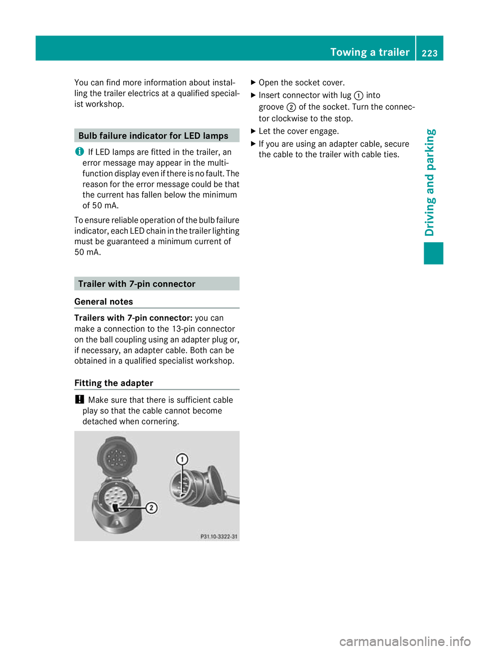
detached when cornering. X
Open the socket cover.
X Insert connector with lug :into
groove ;of the socket. Turn the connec-
tor clockwise to the stop.
X Let the cover engage.
X If you are using an adapter cable, secure
the cable to the trailer with cable ties. Towing
atrailer
223Driving an d parking Z