2012 MERCEDES-BENZ CLS SHOOTING BRAKE lock
[x] Cancel search: lockPage 293 of 405
Useful information
i This Owner's Manual describes all mod-
els, series and optional equipment for your
vehicle that were available at the time of
going to press. National variations are pos-
sible. Note that your vehicle may not be
equipped with all of the functions descri-
bed. This is also the case for systems and
functions relevant to safety.
i Read the information on qualified special-
ist workshops: (Y page 24). Stowage areas
Loading guidelines
G
WARNING
Secure and position the load as described in
the loading guidelines.
Otherwise, vehicle occupants could
be injured by the load being thrown around in
the even tofsharp braking, a sudden change
in direction or an accident.
You will find further information in the "Secur-
ing a load" section.
Even if you follow all the loading guidelines,
the load will increase the risk of injury in the
event of an accident. G
WARNING
Keep the boot lid/tailgate closed while the
vehicle is in operation. Otherwise, exhaust
fumes could enter the vehicle interior and poi-
son you.
The handling characteristics of a laden vehi-
cle are dependent on the distribution of the
load within the vehicle. For this reason, you
should observe the following notes when
transporting a load:
R when transporting a load, never exceed the
maximum permissible gross vehicle weight or the permissible axle loads for the vehicle
(including occupants).
R position heavy loads as far forwards as pos-
sible and as low down in the boot/luggage
compartmenta s possible.
R the load must not protrude above the upper
edge of the seat backrests.
R always place the load against the rear or
front seat backrests. Make sure that the
seat backrests are securely locked into
place.
R always place the load behind unoccupied
seats if possible.
R secure the load with sufficiently strong and
wear-resistant lashing material. pad sharp
edges for protection.
i Load restraints are available at any quali-
fied specialist workshop, e.g. a Mercedes-
Benz Service Centre. Stowage compartments
Important safety notes G
WARNING
The stowage compartments must be closed
when items are stored in them. Luggage nets
are not designed to secure heavy items of
luggage.
You or other vehicle occupants could be
injured by objects being thrown around if you:
R brake sharply
R change direction suddenly
R are involved in an accident
Sharp-edged and fragile objects must not be
placed in the luggage net.
Do not place hard objects in the map pockets.
Objects must not protrude from the map
pockets. 290
Stowage areasStowing and features
Page 294 of 405
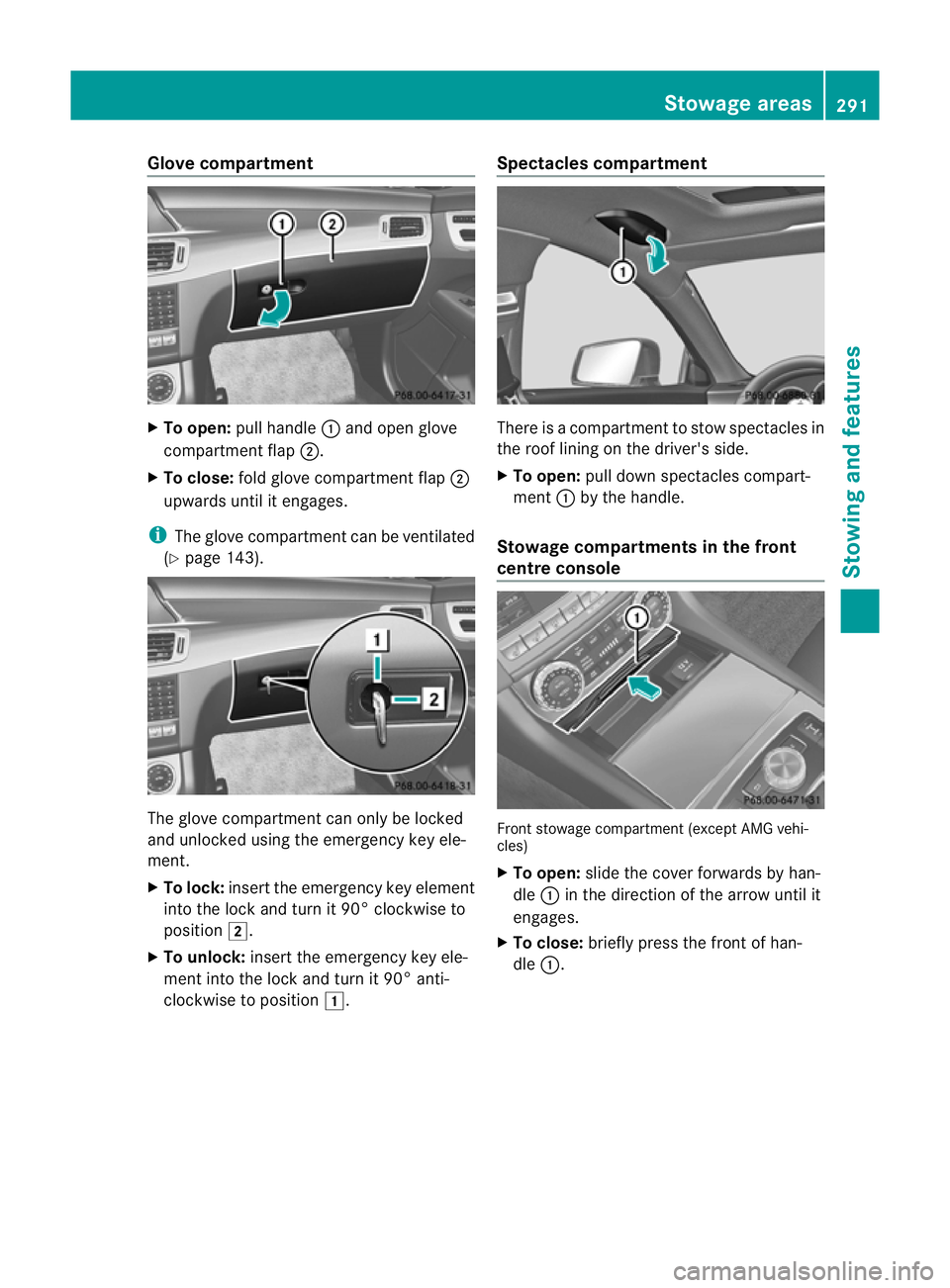
Glove compartment
X
To open: pull handle :and open glove
compartment flap ;.
X To close: fold glove compartment flap ;
upwards until it engages.
i The glove compartment can be ventilated
(Y page 143). The glove compartment can only be locked
and unlocked using the emergency key ele-
ment.
X To lock: insert the emergency key element
into the lock and turn it 90° clockwise to
position 2.
X To unlock: insert the emergency key ele-
ment into the lock and turn it 90° anti-
clockwise to position 1. Spectacles compartment There is a compartment to stow spectacles in
the roof lining on the driver's side.
X
To open: pull down spectacles compart-
ment :by the handle.
Stowage compartments in the front
centre console Front stowage compartment (except AMG vehi-
cles)
X
To open: slide the cover forwards by han-
dle :in the direction of the arrow until it
engages.
X To close: briefly press the front of han-
dle :. Stowage areas
291Stowing and features Z
Page 303 of 405
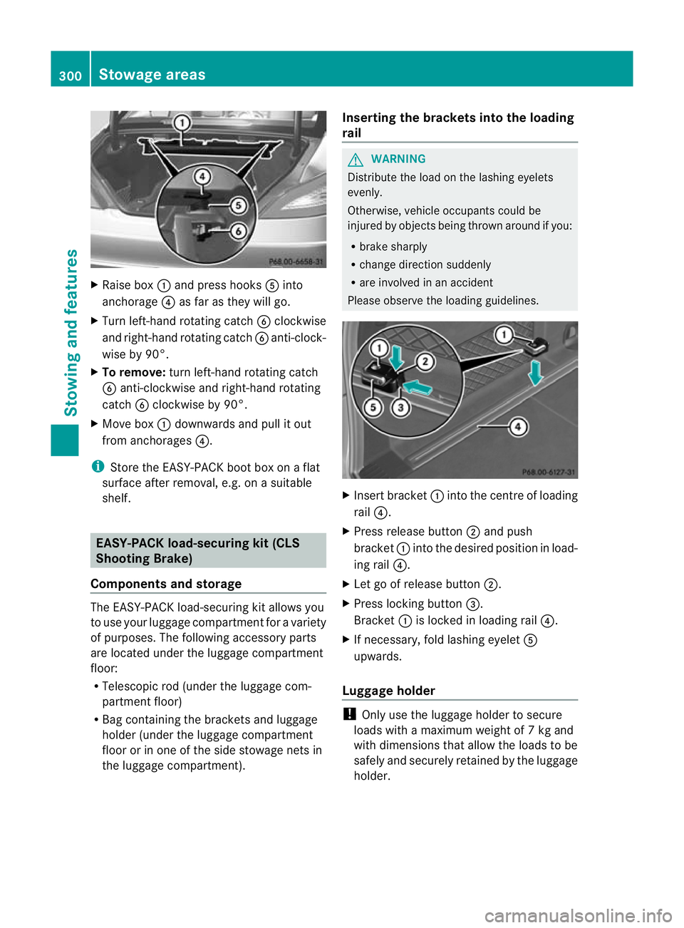
X
Raise box :and press hooks Ainto
anchorage ?as far as they will go.
X Turn left-hand rotating catch Bclockwise
and right-hand rotating catch Banti-clock-
wise by 90°.
X To remove: turn left-hand rotating catch
B anti-clockwise and right-hand rotating
catch Bclockwise by 90°.
X Move box :downwards and pull it out
from anchorages ?.
i Store the EASY-PACK boot box on a flat
surface after removal, e.g. on a suitable
shelf. EASY-PACK load-securing kit (CLS
Shooting Brake)
Components and storage The EASY-PACK load-securing ki
tallows you
to use your luggage compartmen tfor a variety
of purposes. The following accessory parts
are located under the luggage compartment
floor:
R Telescopic rod (under the luggage com-
partment floor)
R Bag containing the brackets and luggage
holder (under the luggage compartment
floor or in one of the side stowage nets in
the luggage compartment). Inserting the brackets into the loading
rail G
WARNING
Distribute the load on the lashing eyelets
evenly.
Otherwise, vehicle occupants could be
injured by objects being thrown around if you:
R brake sharply
R change direction suddenly
R are involved in an accident
Please observe the loading guidelines. X
Insert bracket :into the centre of loading
rail ?.
X Press release button ;and push
bracket :into the desired position in load-
ing rail ?.
X Let go of release button ;.
X Press locking button =.
Bracket :is locked in loading rail ?.
X If necessary, fold lashing eyelet A
upwards.
Luggage holder !
Only use the luggage holder to secure
loads with a maximum weight of 7kg and
with dimensions that allow the loads to be
safely and securely retained by the luggage
holder. 300
Stowage areasStowing and features
Page 304 of 405
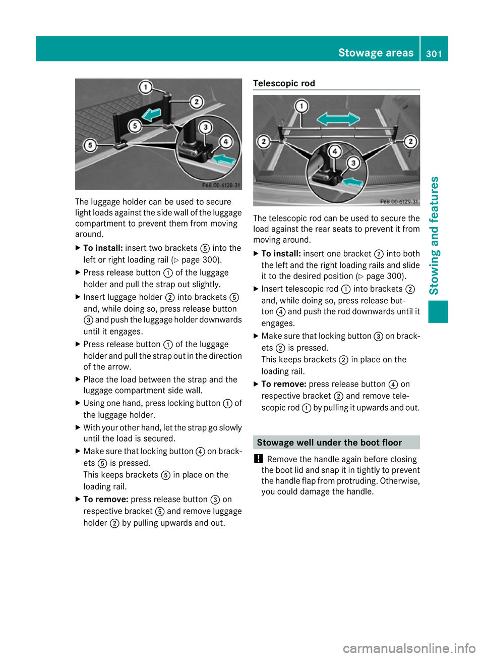
The luggage holder can be used to secure
light loads against the side wall of the luggage
compartment to prevent them from moving
around.
X To install: insert two brackets Ainto the
left or right loading rail (Y page 300).
X Press release button :of the luggage
holder and pull the strap out slightly.
X Insert luggage holder ;into brackets A
and, while doing so, press release button
= and push the luggage holder downwards
until it engages.
X Press release button :of the luggage
holder and pull the strap out in the direction
of the arrow.
X Place the load between the strap and the
luggage compartment side wall.
X Using one hand, press locking button :of
the luggage holder.
X With your other hand, let the strap go slowly
until the load is secured.
X Make sure that locking button ?on brack-
ets Ais pressed.
This keeps brackets Ain place on the
loading rail.
X To remove: press release button =on
respective bracket Aand remove luggage
holder ;by pulling upwards and out. Telescopic rod
The telescopic rod can be used to secure the
load against the rear seats to prevent it from
moving around.
X
To install: insert one bracket ;into both
the left and the right loading rails and slide
it to the desired position (Y page 300).
X Insert telescopic rod :into brackets ;
and, while doing so, press release but-
ton ?and push the rod downwards until it
engages.
X Make sure that locking button =on brack-
ets ;is pressed.
This keeps brackets ;in place on the
loading rail.
X To remove: press release button ?on
respective bracket ;and remove tele-
scopic rod :by pulling it upwards and out. Stowage well under the boot floor
! Remove the handle again before closing
the boot lid and snap it in tightly to prevent
the handle flap from protruding. Otherwise,
you could damage the handle. Stowage areas
301Stowing and features Z
Page 309 of 405
X
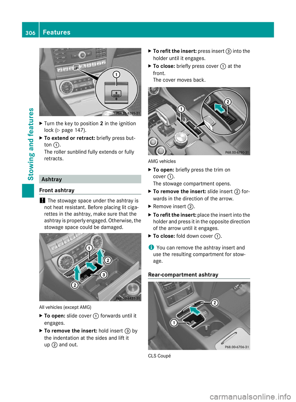
Turn the key to position 2in the ignition
lock (Y page 147).
X To extend or retract: briefly press but-
ton :.
The roller sunblind fully extends or fully
retracts. Ashtray
Front ashtray !
The stowage space under the ashtray is
not heat resistant .Before placing lit ciga-
rettes in the ashtray, make sure that the
ashtray is properly engaged. Otherwise, the
stowage space could be damaged. All vehicles (except AMG)
X
To open: slide cover :forwards until it
engages.
X To remove the insert: hold insert=by
the indentation at the sides and lift it
up ; and out. X
To refit the insert: press insert=into the
holder until it engages.
X To close: briefly press cover :at the
front.
The cover moves back. AMG vehicles
X
To open: briefly press the trim on
cover :.
The stowage compartment opens.
X To remove the insert: slide insert;for-
wards in the direction of the arrow.
X Remove insert ;.
X To refit the insert: place the insert into the
holder and press it in the opposite direction
of the arrow until it engages.
X To close: fold down cover :.
i You can remove the ashtray insert and
use the resulting compartment for stow-
age.
Rear-compartment ashtray CLS Coupé306
FeaturesStowing and features
Page 310 of 405
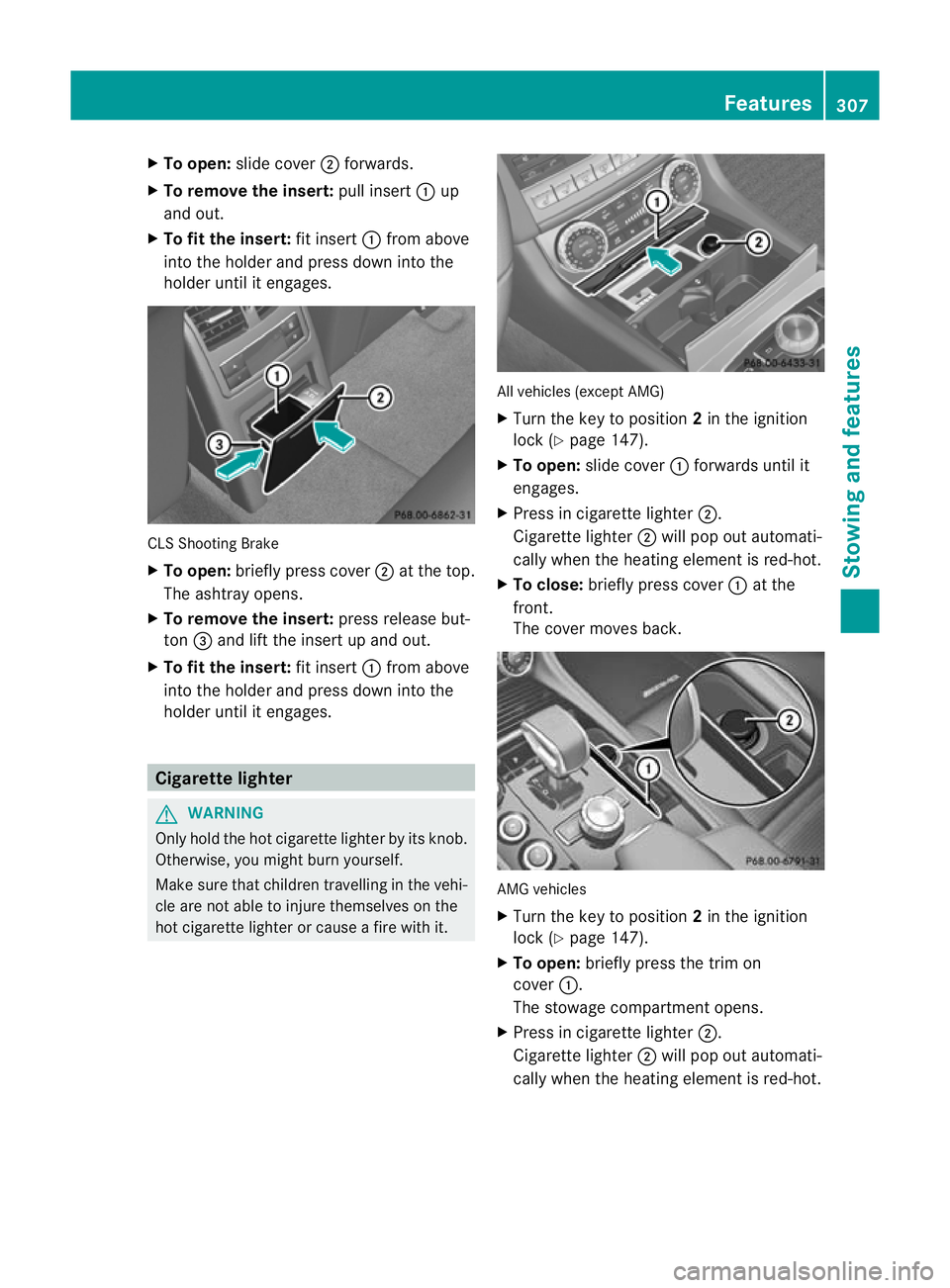
X
To open: slide cover ;forwards.
X To remove the insert: pull insert:up
and out.
X To fit the insert: fit insert:from above
into the holde rand press down into the
holde runtil it engages. CLS Shooting Brake
X
To open: briefly press cover ;at the top.
The ashtray opens.
X To remove the insert: press release but-
ton =and lift the insert up and out.
X To fit the insert: fit insert:from above
into the holde rand press down into the
holde runtil it engages. Cigarette lighter
G
WARNING
Only hold the hot cigarette lighte rby its knob.
Otherwise, you might burn yourself.
Make sure that children travelling in the vehi-
cle are no table to injure themselves on the
hot cigarette lighter or cause a fire with it. All vehicles (excep
tAMG)
X Turn the key to position 2in the ignition
lock (Y page 147).
X To open: slide cover :forwards until it
engages.
X Press in cigarette lighter ;.
Cigarette lighter ;will pop out automati-
cally when the heating element is red-hot.
X To close: briefly press cover :at the
front.
The cover moves back. AMG vehicles
X
Turn the key to position 2in the ignition
lock (Y page 147).
X To open: briefly press the trim on
cover :.
The stowage compartmento pens.
X Press in cigarette lighter ;.
Cigarette lighter ;will pop out automati-
cally when the heating element is red-hot. Features
307Stowing and features Z
Page 311 of 405
12
Vsockets
General notes X
Turn the key to position 1in the ignition
lock (Y page 147).
The sockets can be used for accessories with
a maximum draw of 180 W (15 A). Accesso-
ries include such items as lamps or chargers
for mobile phones.
If you use the sockets for long periods when
the engine is switched off ,the battery may
discharge.
i An emergency cut-offe nsures thatthe on-
board voltage does not drop too low. If the
on-board voltage is too low, the power to
the sockets is automatically cut. This
ensures that there is sufficient power to
start the engine.
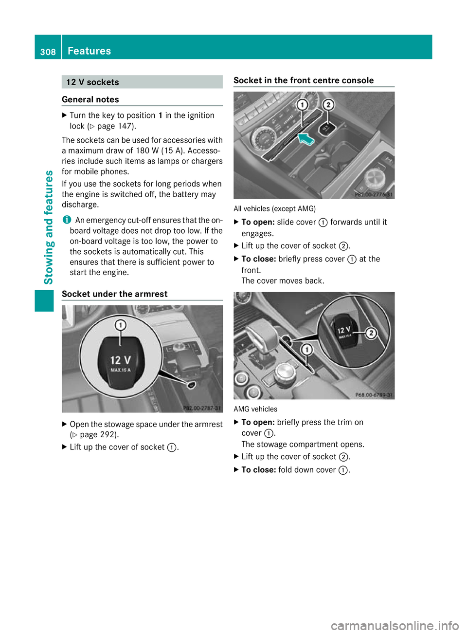
Socket under the armrest X
Open the stowage space under the armrest
(Y page 292).
X Lift up the cover of socket :.Socket in the front centre console All vehicles (except AMG)
X
To open: slide cover :forwards until it
engages.
X Lift up the cover of socket ;.
X To close: briefly press cover :at the
front.
The cover moves back. AMG vehicles
X
To open: briefly press the trim on
cover :.
The stowage compartmento pens.
X Lift up the cover of socket ;.
X To close: fold down cover :.308
FeaturesStowing and features
Page 313 of 405
An exterio
raerial has the following advan-
tages:
R it conducts the electromagnetic fields gen-
erated by a wireless device to the exterior.
R the field strength in the vehicle interior is
lower than in a vehicle that does not have
an exterior aerial.
i There are various mobile phone brackets
that may be fitted in your vehicle; in some
cases, these are country-specific.
i You can connect a Bluetooth ®
-capable
mobile phone with Audio 20, Audio 50 or
COMAND Online via the Bluetooth ®
inter-
face. This also applies if your vehicle is
equipped with convenience telephony.
More information on suitable mobile phones,
mobile phone brackets and on connecting
Bluetooth ®
-capable mobile phones with
Audio 20, Audio 50 or COMAND Online can
be obtained:
R at your Mercedes-Benz Service Centre
R on the Internet at http://www.mercedes-
benz.com/connect
i The functions and services available when
you use the phone depend on your mobile
phone model and service provider.
Using amobile phone If the mobile phone is inserted in the mobile
phone bracket, you can speak to the person
you are calling using the hands-free system.
X
Open the telephone compartment
(Y page 292).
X If required by the desig nofthe mobile
phone bracket, install the sliding adapter
(Y page 311).
X Insert the mobile phone into the mobile
phone bracket (see the separate installa-
tion instructions for the mobile phone fit-
ting).
i On some mobile phone brackets, you first
have to connect the mobile phone via Blue-
tooth ®
to the mobile phone bracket (see the separate operating instructions for the
mobile phone bracket).
If this is the case, the mobile phone does
not have to be inserted into the bracket for
you to be able to use the telephone func-
tions. However, the charging function and
aerial function are not available.
Operating the mobile phone You can operate the telephone using the
6
and~ buttons on the multifunction
steering wheel. You can operate other mobile
phone functions via the on-board computer
(Y page 235).
When you remove the key from the ignition
lock, the mobile phone stays switched on.
However, you can no longer use the hands-
free system.
If you have an active call and would like to
take the key out of the ignition lock, first
remove the mobile phone from the bracket.
Otherwise, the call is ended.
i When using a bracket connected to the
mobile phone via Bluetooth ®
:
If you wish to continue a call in private
mode, you will need to perform the neces-
sary steps on the mobile phone. Informa-
tion can be found in the separate mobile
phone operating instructions.
i When using a bracket connected to the
mobile phone via Bluetooth ®
and you wish
to proceed with a call:
Switch to private mode before removing
the key from the ignition lock. Otherwise, it
may take up to 20 seconds, before the
mobile phone separates from the system.
Only then can the telephone call continue.
Information on the necessary steps for set-
ting up "private mode" can be found in the
separate mobile phone operating instruc-
tions.
i Not all mobile phones support "private
mode". 310
FeaturesStowing and features