2012 MERCEDES-BENZ CLS COUPE clock
[x] Cancel search: clockPage 140 of 373
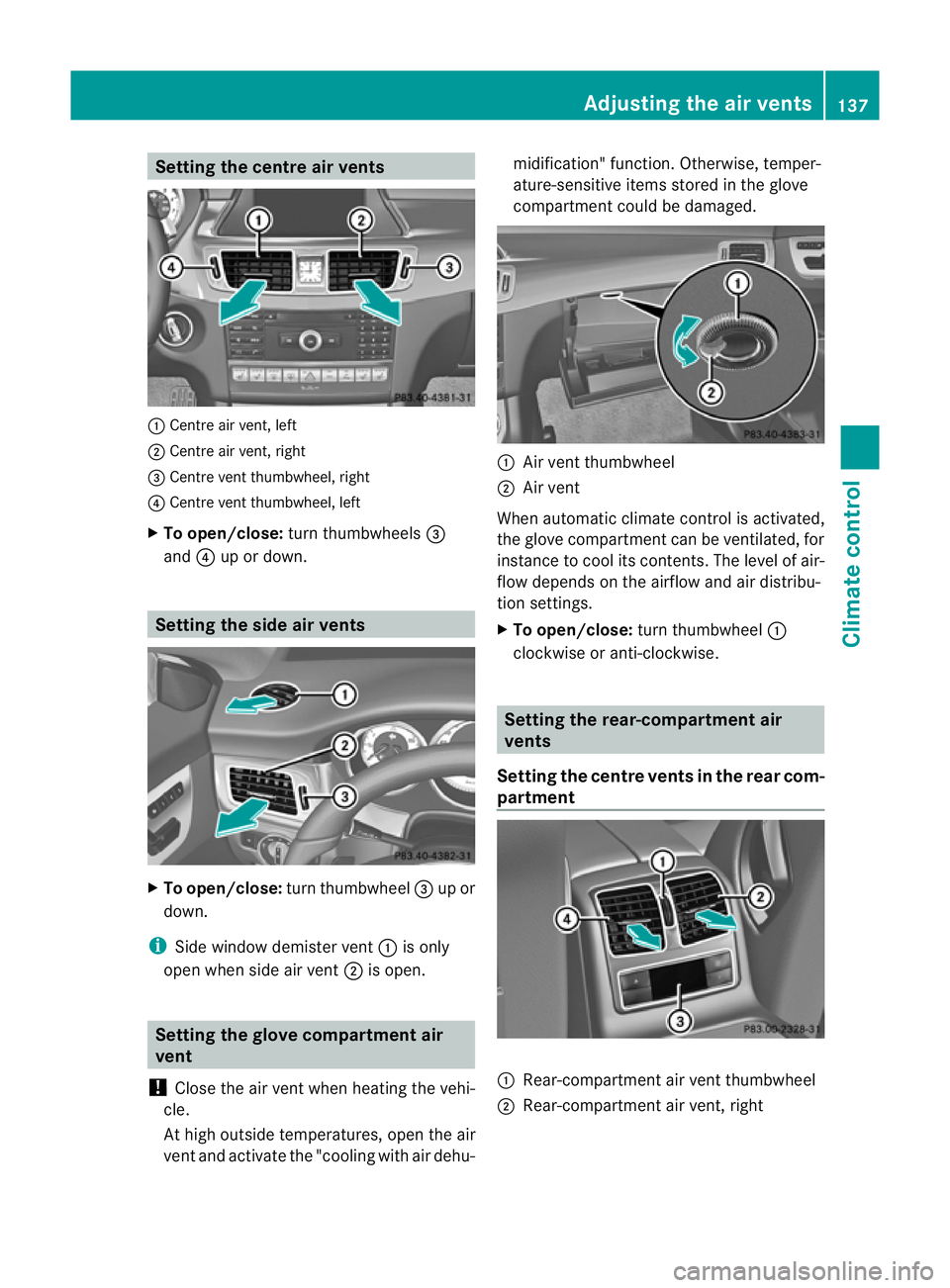
Setting the centre air vents
:
Centre air vent, left
; Centre air vent, right
= Centre vent thumbwheel, right
? Centre vent thumbwheel, left
X To open/close: turn thumbwheels =
and ?up or down. Setting the side air vents
X
To open/close: turn thumbwheel =up or
down.
i Side window demister vent :is only
open when side air vent ;is open. Setting the glove compartment air
vent
! Close the air vent when heating the vehi-
cle.
At high outside temperatures, open the air
vent and activate the "cooling with air dehu- midification" function. Otherwise, temper-
ature-sensitive items stored in the glove
compartmen
tcould be damaged. :
Air vent thumbwheel
; Air vent
When automatic climate control is activated,
the glove compartment can be ventilated, for
instance to cool its contents.T he level of air-
flow depends on the airflow and air distribu-
tion settings.
X To open/close: turn thumbwheel :
clockwise or anti-clockwise. Setting the rear-compartment air
vents
Setting the centre vents in the rear com-
partment :
Rear-compartment air vent thumbwheel
; Rear-compartment air vent,r ight Adjusting the air vents
137Climatecontrol Z
Page 160 of 373
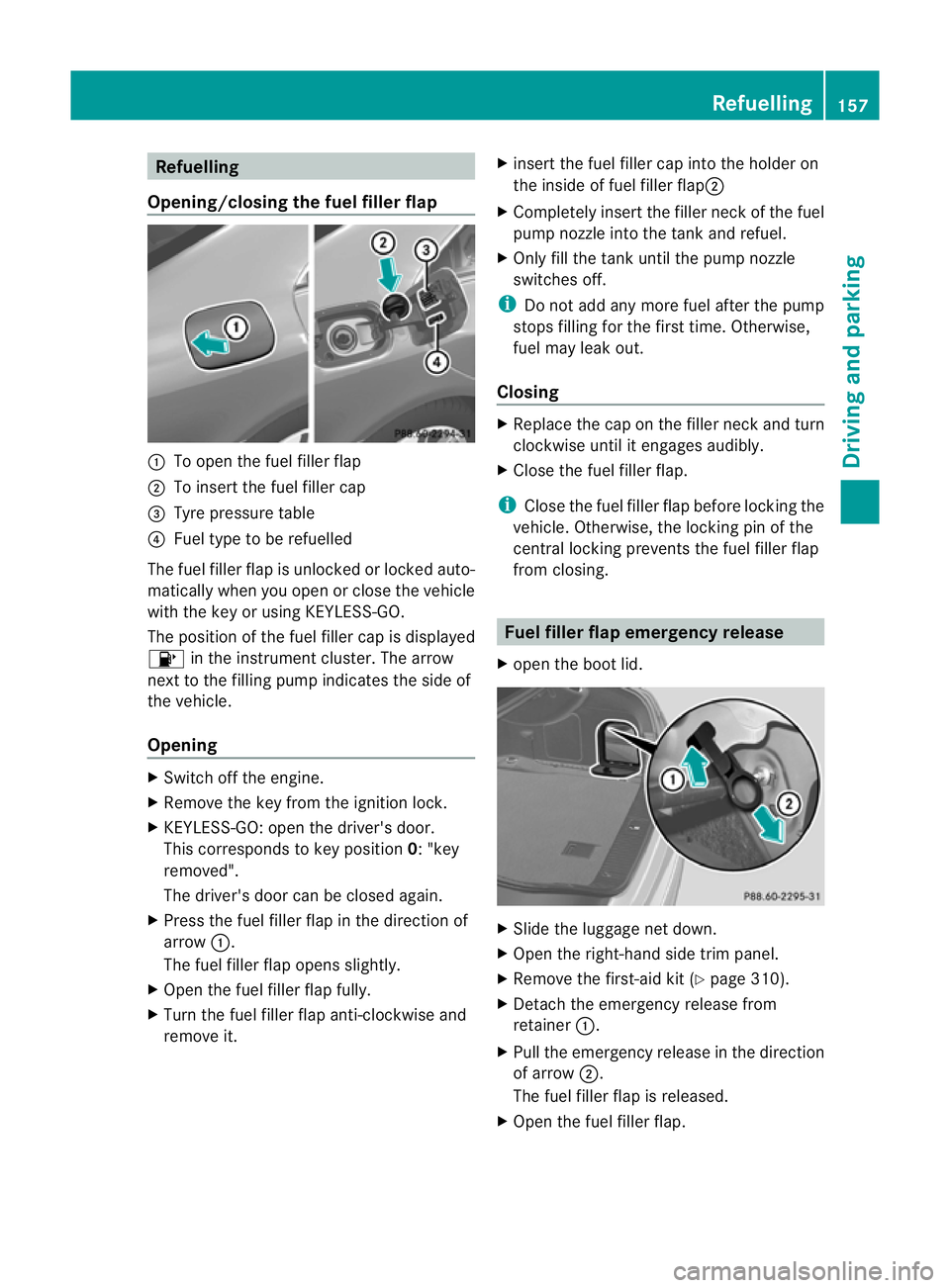
Refuelling
Opening/closing the fue lfille rflap :
To open the fuel filler flap
; To inser tthe fuel filler cap
= Tyre pressure table
? Fuel type to be refuelled
The fuel filler flap is unlocked or locked auto-
matically when you open or close the vehicle
with the key or using KEYLESS-GO.
The position of the fuel filler cap is displayed
8 in the instrumentc luster. The arrow
next to the filling pump indicates the side of
the vehicle.
Opening X
Switch off the engine.
X Remove the key from the ignition lock.
X KEYLESS-GO: open the driver's door.
This corresponds to key position 0:"key
removed".
The driver's door can be closed again.
X Press the fuel filler flap in the direction of
arrow :.
The fuel filler flap opens slightly.
X Open the fuel filler flap fully.
X Turn the fuel filler flap anti-clockwise and
remove it. X
insert the fuel filler cap into the holder on
the inside of fuel filler flap ;
X Completely insert the filler neck of the fuel
pump nozzle into the tank and refuel.
X Only fill the tank until the pump nozzle
switches off.
i Do not add any more fuel after the pump
stops filling for the first time. Otherwise,
fuel may leak out.
Closing X
Replace the cap on the filler neck and turn
clockwise until it engages audibly.
X Close the fuel filler flap.
i Close the fuel filler flap before locking the
vehicle. Otherwise, the locking pin of the
central locking prevents the fuel filler flap
from closing. Fuel filler flap emergency release
X open the boot lid. X
Slide the luggage net down.
X Open the right-hand side trim panel.
X Remove the first-aid kit (Y page 310).
X Detach the emergency release from
retainer :.
X Pull the emergency release in the direction
of arrow ;.
The fuel filler flap is released.
X Open the fuel filler flap. Refuelling
157Driving and parking Z
Page 184 of 373
Activating RACE START
X
Depress th ebrak epedal wit hyour left foot
and keep it depressed.
X Turn the drive program selector clockwise
(Y page 151) until the RSlamp lights up.
The RACE START Confirm: Paddle UP Cancel: Paddle DOWN message appears
in the multifunction display.
i If the activation conditions are no longer
fulfilled, RACE START is cancelled. The
RACE START cancelled message
appears in the multifunction display.
X To cancel: pull the left steerin gwheel shift
paddle (Y page 152).
or
X To confirm: pull the right steerin gwheel
shift paddle (Y page 152).
The RACE START available Depress accelerator message appears in the mul-
tifunction display.
i If you do not depress the accelerator
pedal fully within two seconds, RACE
START is cancelled. The RACE START not
possible See Owner's Manual message
appears in the multifunction display.
X Fully depress the accelerator pedal.
The engine speed rises to approximately
3500 rpm.
The RACE START Release brake to start message appears in the multifunc-
tion display.
i If you do not release the brake pedal
within five seconds, RACE START is cancel-
led. The RACE START cancelled mes-
sage appears in the multifunction display.
X Take your foot off the brake, but keep the
accelerator pedal depressed.
The vehicle pulls away at maximum accel-
eration.
The RACE START active message appears
in the multifunction display.
RACE START is deactivated when the vehicle
reaches aspeed of approximately 50 km/h. Drive program
S+is activated. SPORT han-
dling mode remains activated.
RACE START is deactivated immediately if
you release the accelerator pedal during
RACE START or if any of the activation condi-
tions are no longer fulfilled. The RACE START
not possible See Owner's Manual mes-
sage appears in the multifunction display.
i After using it several times in short suc-
cession, RACE START will be unavailable
until acertain distance has been driven. AIRMATIC
Vehicle level Important safety notes
G
WARNING
If you have selected "Comfort tuning", the
vehicle will be lowered if you lock it within
60 seconds of the engine being switched off.
Make sure, therefore, that nobody is in the
vicinit yofthe wheel housing or under the
vehicle when you lock the vehicle. Otherwise,
limbs could become trapped.
! The vehicle is lowered by about 15 mm if:
R you have selected "Comfort tuning"
R you switch off the engine and
R you lock the vehicle within approximately
60 seconds
When parking, position your vehicle so that
it does not make contact with the kerb as
the vehicle is lowered. Your vehicle could
otherwise be damaged.
Your vehicle regulates its height automati-
cally. All-round level control ensures the best
possible suspension and constant ground
clearance, even with aladen vehicle. When
you drive fast, the vehicle is lowered auto-
matically to improve driving safety and to
reduce fuel consumption. Driving systems
181Driving and parking Z
Page 276 of 373
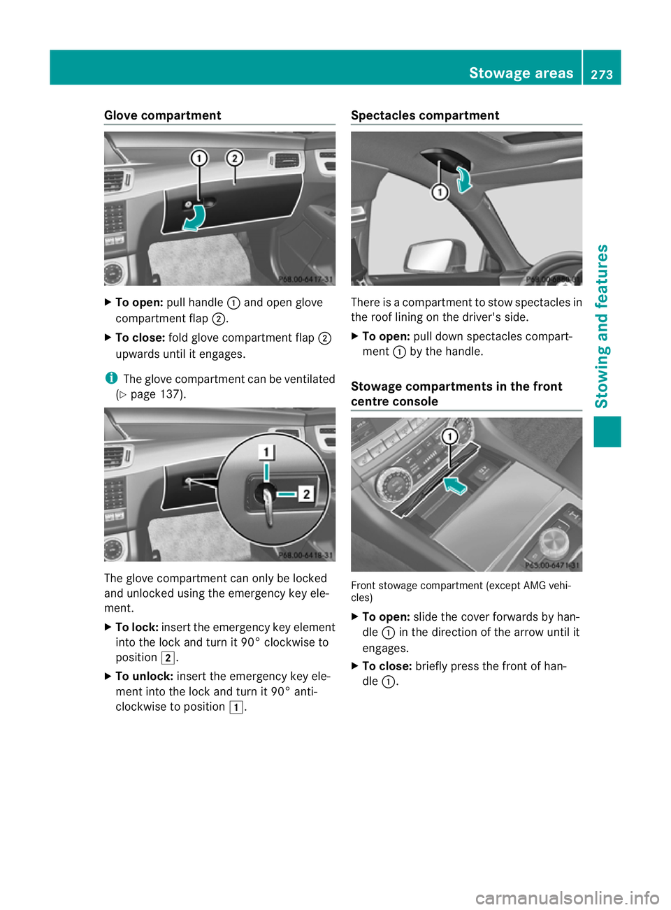
Glove compartment
X
To open: pullhandle :and open glove
compartment flap ;.
X To close: fold glove compartment flap ;
upwards until it engages.
i The glove compartment can be ventilated
(Y page 137). The glove compartment can only be locked
and unlocked using the emergency key ele-
ment.
X To lock: insert the emergency key element
into the lock and turn it 90° clockwise to
position 2.
X To unlock: insert the emergency key ele-
ment into the lock and turn it 90° anti-
clockwise to position 1. Spectacles compartment There is
acompartment to stow spectacle sin
the roof lining on the driver's side.
X To open: pulldown spectacle scompart-
ment :by the handle.
Stowag ecompartments in the front
centre console Front stowag
ecompartment (except AMG vehi-
cles)
X To open: slidethe cover forwards by han-
dle :in the direction of the arrow until it
engages.
X To close: brieflypress the front of han-
dle :. Stowage areas
273Stowing and features Z
Page 281 of 373
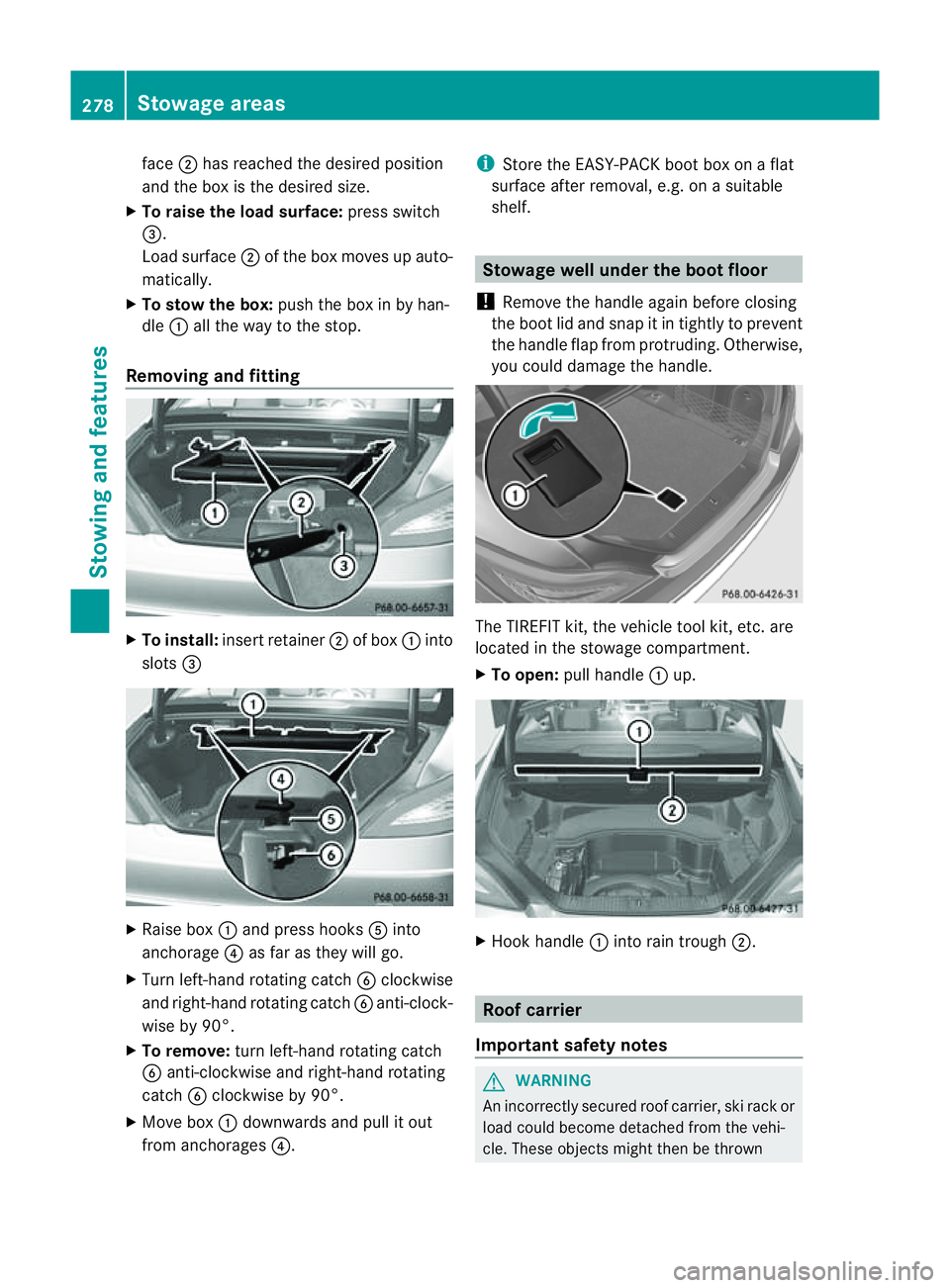
face
;has reache dthe desired position
and the box is the desired size.
X To raise the load surface: press switch
=.
Load surface ;of the box moves up auto-
matically.
X To stow the box: pushthe box in by han-
dle :allt he waytot he stop.
Removing and fitting X
To install: insert retainer ;of box :into
slots = X
Raise box :and press hooks Ainto
anchorage ?as far as they wil lgo.
X Turn left-hand rotating catch Bclockwise
and right-hand rotating catch Banti-clock-
wis eby9 0°.
X To remove: turn left-hand rotating catch
B anti-clockwise and right-hand rotating
catch Bclockwise by 90°.
X Move box :downward sand pul litout
from anchorages ?. i
Store the EASY-PACK boot box on aflat
surface after removal, e.g. on asuitable
shelf. Stowage well under the boo
tfloor
! Remove the handle again befor eclosing
the boot lid and snap it in tightly to prevent
the handle flap fro mprotruding. Otherwise,
you coul ddamage the handle. The TIREFIT kit, the vehicl
etool kit, etc. are
located in the stowage compartment.
X To open: pullhandle :up. X
Hook handle :into rain trough ;. Roof carrier
Important safety notes G
WARNING
An incorrectly secure droof carrier, ski rack or
load could become detached from the vehi-
cle. These object smight then be thrown 278
Stowage areasStowing and features
Page 301 of 373
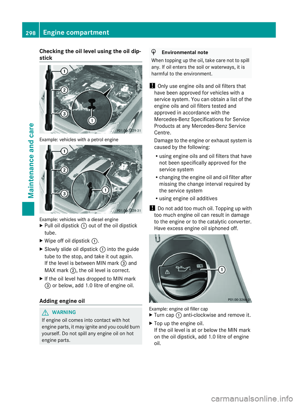
Checking th
eoil level usin gthe oil dip-
stick Example
:vehicles with apetrol engine Example: vehicles with
adiesel engine
X Pull oil dipstick :out of the oil dipstick
tube.
X Wipe off oil dipstick :.
X Slowly slide oil dipstick :into the guide
tube to the stop, and take it out again.
If the level is between MIN mark =and
MAX mark ;,the oil level is correct.
X If the oil level has dropped to MIN mark
= or below, add 1.0 litre of engine oil.
Adding engine oil G
WARNING
If engine oil comes into contact with hot
engine parts, it may ignite and you could burn
yourself. Do not spill any engine oil on hot
engine parts. H
Environmental note
When topping up the oil, take care not to spill
any. If oil enters the soil or waterways, it is
harmful to the environment.
! Only use engine oils and oil filters that
have been approved for vehicles with a
service system. You can obtain alist of the
engine oils and oil filters tested and
approved in accordance with the
Mercedes-Benz Specification sfor Service
Product satany Mercedes-Benz Service
Centre.
Damage to the engine or exhaust system is
caused by the following:
R using engine oils and oil filters that have
not been specifically approved for the
service system
R changin gthe engine oil and oil filter after
missing the change interval required by
the service system
R using engine oil additives
! Do not add too much oil. Topping up with
too much engine oil can result in damage
to the engine or to the catalytic converter.
Have exces sengine oil siphoned off. Example: engine oil filler cap
X
Turn cap :anti-clockwise and remove it.
X Top up the engine oil.
If the oil level is at or below the MIN mark
on the oil dipstick ,add 1.0 litre of engine
oil. 298
Engine compartmentMaintenance and care
Page 302 of 373
X
Replac ecap : on th efiller neck and turn
clockwise.
Mak esuret hatthe cap locks securel yinto
place.
X Chec kthe oil level again with the oil dip-
stick (Y page 298).
For further information on engine oil, see
(Y page 363). Other service products
Checking the coolant level G
WARNING
The cooling system is pressurised. Therefore,
only unscrew the cap once the engine has
cooled down. The coolant temperature gauge
must display less than 70 †.Otherwise, you
could be scalded if hot coolant escapes. X
Park the vehicl eonalevel surface.
Onl ycheck the coolant level if the vehicle
is on alevel surface and the engine has
coole ddown.
X Turn the key to position 2in the ignition
lock (Y page 141).
On vehicles with KEYLESS-GO, press the
Start/Stop button twice (Y page 141).
X Check the coolant temperatur edisplay in
the instrument cluster.
Th ec oolant temperatur emustbeb elow
70 †.
X Turn the key to position 0(Y page 141) in
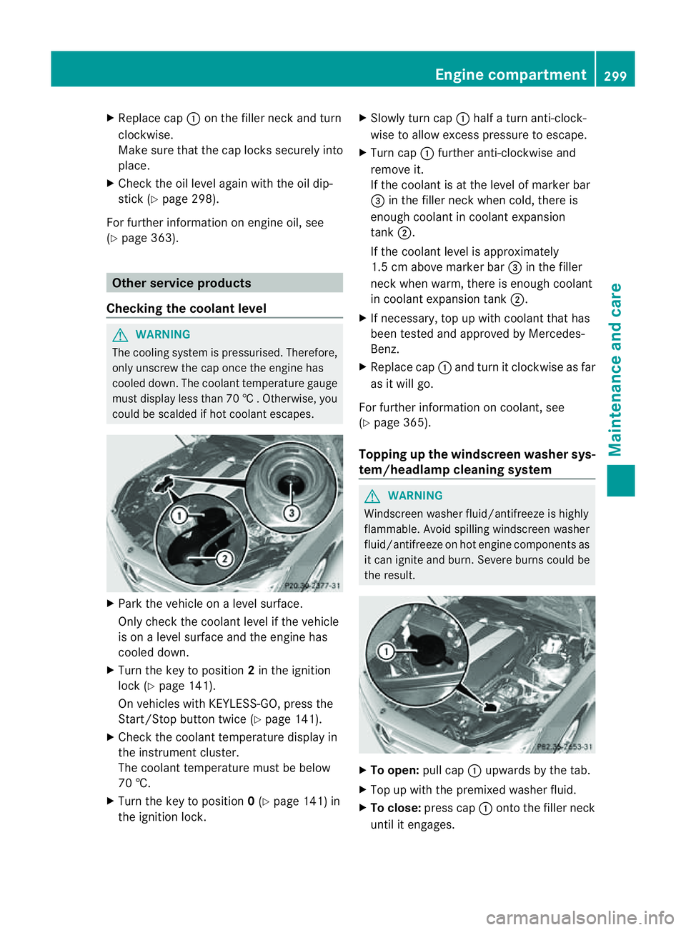
the ignition lock. X
Slowl yturnc ap : half aturna nti-clock-
wise to allow exces spressure to escape.
X Turn cap :further anti-clockwis eand
remove it.
If th ecoolan tisatt heleve lofm arkerbar
= in th efille rneck when cold, ther eis
enough coolant in coolant expansion
tank ;.
If the coolant level is approximately
1.5 cm above marker bar =in the filler
neckw hen warm, there is enough coolant
in coolant expansion tank ;.
X If necessary, top up with coolant that has
been tested and approved by Mercedes-
Benz.
X Replace cap :and turn it clockwise as far
as it will go.
For further information on coolant, see
(Y page 365).
Topping up the windscreen washer sys-
tem/headlam pcleaning system G
WARNING
Windscreen washer fluid/antifreez eishighly
flammable. Avoid spilling windscreen washer
fluid/antifreez eonhot engin ecomponent sas
it can ignit eand burn. Severe burns could be
the result. X
To open: pull cap:upwards by the tab.
X Top up with the premixed washer fluid.
X To close: press cap :ontothe filler neck
until it engages. Engine compartment
299Maintenance and care Z
Page 321 of 373
Otherwise, the vehicle's electronic sys-
tem may be damaged.
R in vehicles with automatic transmission,
the transmission is locked in position P
after disconnecting the battery. The vehi-
cle is secured against rolling away. You
can then no longer move the vehicle.
The battery and the cover of the positive
terminal clamp must be fitted securely dur-
ing operation.
In order for the battery to achieve the maxi-
mum possibles ervice life, it must always be
sufficiently charged.
The vehicle battery, like other batteries, can
discharge over time if you do not use the
vehicle. In such cases, have the battery dis-
connected at aqualified specialist workshop.
You can also charge the battery with a
charger recommended by Mercedes-Benz.
For more information, please contact aquali-
fied specialist workshop.
Have the battery charge checked more fre-
quently if you use the vehicle mainly for short
trips or if you leave it standing idle for a
lengthy period. Consult aqualified specialist
workshop if you wish to leave your vehicle
parked up for along period of time.
i When you park the vehicle, remove the
key if you do not require any electrical con-
sumers. The vehicle will then use very little
energy, thus conserving battery power.
i After an interruption of the power supply,
e.g. the battery was discharged, you have
to:
R set the clock. Information on setting the
clock can be found in the separate oper-
ating instructions.
On vehicles with COMAND Online and a
navigation system, the clock is set auto-
matically.
R reset the function for folding the exterior
mirrors in/out automatically, by folding
the mirrors out once (Y page 106). Charging the battery
G
WARNING
Only charge the battery in awell-ventilated
area. As the battery is being charged, gases
can escape and generate minor explosions.
This could injure you and other persons or
cause damage to the paintwork or acid cor-
rosion on the vehicle.
You can obtain information on battery charg-
ers which allow the battery to be charged
while still installed from aqualified specialist
workshop. G
WARNING
There is arisk of acid burns during the charg-
ing process due to the gases which escape
from the battery. Do not lean over the battery
during the charging process. G
WARNING
Battery acid is caustic. Avoid contact with the
skin, eyes or clothing.
! Only charge the installed battery with a
battery charger which has been tested and
approved by Mercedes-Benz.T hese battery
chargers allow the battery to be charged
while still installed in the vehicle.
! Only use battery chargers with amaxi-
mum charging voltage of 14.8 V.
! Only charge the battery using the jump-
start connection point.
The jump-starting connection point is in the
engine compartment( Ypage 319).
Read the battery charger's operating instruc-
tions before charging the battery.
X Open the bonnet (Y page 296).
X Connect the battery charger to the positive
terminal and earth point in the same order
as when connecting the donor battery in
the jump-starting procedure
(Y page 319). 318
Battery (vehicle)Breakdown assistance