2012 KIA Soul check oil
[x] Cancel search: check oilPage 330 of 393

Maintenance
20
7
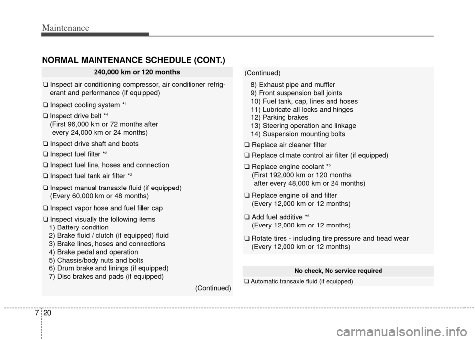
240,000 km or 120 months
❑ Inspect air conditioning compressor, air conditioner refrig-
erant and performance (if equipped)
❑ Inspect cooling system *1
❑Inspect drive belt *4
(First 96,000 km or 72 months after
every 24,000 km or 24 months)
❑ Inspect drive shaft and boots
❑ Inspect fuel filter *2
❑Inspect fuel line, hoses and connection
❑Inspect fuel tank air filter *2
❑Inspect manual transaxle fluid (if equipped)
(Every 60,000 km or 48 months)
❑ Inspect vapor hose and fuel filler cap
❑Inspect visually the following items
1) Battery condition
2) Brake fluid / clutch (if equipped) fluid
3) Brake lines, hoses and connections
4) Brake pedal and operation
5) Chassis/body nuts and bolts
6) Drum brake and linings (if equipped)
7) Disc brakes and pads (if equipped)
(Continued)
(Continued)
8) Exhaust pipe and muffler
9) Front suspension ball joints
10) Fuel tank, cap, lines and hoses
11) Lubricate all locks and hinges
12) Parking brakes
13) Steering operation and linkage
14) Suspension mounting bolts
❑ Replace air cleaner filter
❑Replace climate control air filter (if equipped)
❑Replace engine coolant *5
(First 192,000 km or 120 months
after every 48,000 km or 24 months)
❑ Replace engine oil and filter
(Every 12,000 km or 12 months)
❑Add fuel additive *6
(Every 12,000 km or 12 months)
❑Rotate tires - including tire pressure and tread wear
(Every 12,000 km or 12 months)
NORMAL MAINTENANCE SCHEDULE (CONT.)
No check, No service required
❑ Automatic transaxle fluid (if equipped)
Page 332 of 393

Maintenance
22
7
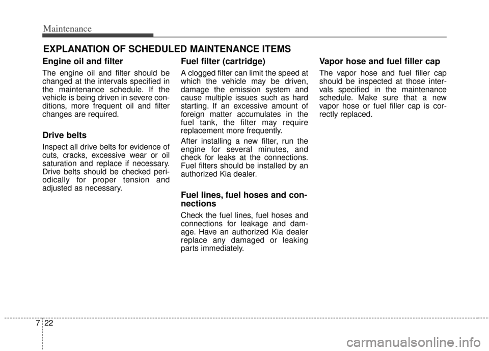
EXPLANATION OF SCHEDULED MAINTENANCE ITEMS
Engine oil and filter
The engine oil and filter should be
changed at the intervals specified in
the maintenance schedule. If the
vehicle is being driven in severe con-
ditions, more frequent oil and filter
changes are required.
Drive belts
Inspect all drive belts for evidence of
cuts, cracks, excessive wear or oil
saturation and replace if necessary.
Drive belts should be checked peri-
odically for proper tension and
adjusted as necessary.
Fuel filter (cartridge)
A clogged filter can limit the speed at
which the vehicle may be driven,
damage the emission system and
cause multiple issues such as hard
starting. If an excessive amount of
foreign matter accumulates in the
fuel tank, the filter may require
replacement more frequently.
After installing a new filter, run the
engine for several minutes, and
check for leaks at the connections.
Fuel filters should be installed by an
authorized Kia dealer.
Fuel lines, fuel hoses and con-
nections
Check the fuel lines, fuel hoses and
connections for leakage and dam-
age. Have an authorized Kia dealer
replace any damaged or leaking
parts immediately.
Vapor hose and fuel filler cap
The vapor hose and fuel filler cap
should be inspected at those inter-
vals specified in the maintenance
schedule. Make sure that a new
vapor hose or fuel filler cap is cor-
rectly replaced.
Page 336 of 393

Maintenance
26
7
ENGINE OIL
Checking the engine oil level
1. Be sure the vehicle is on level
ground.
2. Start the engine and allow it to reach normal operating tempera-
ture. 3. Turn the engine off and wait for a
few minutes (about 5 minutes) for
the oil to return to the oil pan.
4. Pull the dipstick out, wipe it clean, and re-insert it fully.
5. Pull the dipstick out again and check the level. The level should
be between F and L.
If it is near or at L, add enough oil to
bring the level to F.Do not overfill.
Use a funnel to help prevent oil
from being spilled on engine com-
ponents.
WARNING - Radiator hose
Be very careful not to touch the
radiator hose when checking or
adding the engine oil as it may
be hot enough to burn you.
CAUTION - Replace engine oil
Do not overfill the engine oil.
Engine damage may result.
OAM072001
OAM072101L
■ Engine 1.6
■Engine 2.0OAM072003
OAM072102L
■Engine 1.6
■Engine 2.0
Page 341 of 393

731
Maintenance
BRAKE/CLUTCH (IF EQUIPPED) FLUID
Checking the brake/clutch*
fluid level
Check the fluid level in the reservoir
periodically. The fluid level should be
between MAX and MIN marks on the
side of the reservoir.
Before removing the reservoir cap
and adding brake/clutch* fluid, clean
the area around the reservoir cap
thoroughly to prevent brake/clutch*
fluid contamination.
* if equippedIf the level is low, add fluid to the
MAX level. The level will fall with
accumulated mileage. This is a nor-
mal condition associated with the
wear of the brake linings and/or
clutch disc (if equipped). If the fluid
level is excessively low, have the
brake/clutch* system checked by an
authorized Kia dealer.
Use only the specified brake/clutch*
fluid. (Refer to “Recommended lubri-
cants and capacities” in section 8.)
Never mix different types of fluid.In the event the brake/clutch* system
requires frequent additions of fluid,
the vehicle should be inspected by
an authorized Kia dealer.
When changing and adding
brake/clutch* fluid, handle it carefully.
Do not let it come in contact with
your eyes. If brake/clutch* fluid
should come in contact with your
eyes, immediately flush them with a
large quantity of fresh tap water.
Have your eyes examined by a doc-
tor as soon as possible.
Brake/clutch* fluid, which has been
exposed to open air for an extended
time should never be used as its
quality cannot be guaranteed. It
should be disposed of properly.
OAM072007
CAUTION - Proper fluid
Only use brake/clutch fluid in
brake/clutch system. Smallamounts of improper fluids(such as engine oil) can causedamage to the brake/clutch sys-tem.
CAUTION - Brake/clutch fluid
Do not allow brake/clutch* fluid
to contact the vehicle's bodypaint, as paint damage willresult.
Page 350 of 393

Maintenance
40
7
When recharging the battery,
observe the following precautions:
The battery must be removed from
the vehicle and placed in an area
with good ventilation.
Watch the battery during charging, and stop or reduce the charging
rate if the battery cells begin
gassing (boiling) violently or if the
temperature of the electrolyte of
any cell exceeds 49°C (120°F).
Wear eye protection when check- ing the battery during charging.
Disconnect the battery charger in the following order.
1. Turn off the battery charger main switch.
2. Unhook the negative clamp from the negative battery terminal.
3. Unhook the positive clamp from the positive battery terminal.
Before performing maintenance or recharging the battery, turn off all
accessories and stop the engine.
The negative battery cable must be removed first and installed last
when the battery is disconnected.Reset items
Items should be reset after the bat-
tery has been discharged or the bat-
tery has been disconnected.
Sunroof (See section 4)
Climate control system (See section 4)
Clock (See section 4, Audio)
Audio (See section 4)
Page 364 of 393

Maintenance
54
7
FUSES
A vehicle’s electrical system is pro-
tected from electrical overload dam-
age by fuses. This vehicle has 2 fuse panels, one
located in the driver’s side panel bol-
ster, the other in the engine compart-
ment near the battery.
If any of your vehicle’s lights, acces-
sories, or controls do not work, check
the appropriate circuit fuse. If a fuse
has blown, the element inside the
fuse will melt.
If the electrical system does not
work, first check the driver’s side
fuse panel.
Always replace a blown fuse with
one of the same rating.
If the replacement fuse blows, this
indicates an electrical problem. Avoid
using the system involved and imme-
diately consult an authorized Kia
dealer.
Three kinds of fuses are used: blade
type for lower amperage rating, car-tridge type, and multi fuse for higheramperage ratings.
OBK079042
Normal
Normal
Blade type
Cartridge type
Multi fuse Blown
Blown
Normal Blown
WARNING - Fuse replacement
Never replace a fuse with any-
thing but another fuse of the
same rating.
A higher capacity fuse could cause damage and possibly a
fire.
Never install a wire or alu- minum foil instead of the
proper fuse - even as a tem-
porary repair. It may cause
extensive wiring damage and
a possible fire.
CAUTION - Fusereplacement
Do not use a screwdriver or any
other metal object to removefuses because it may cause ashort circuit and damage thesystem.
Page 370 of 393

Maintenance
60
7
Description Fuse rating Protected component
HTD MIRR 10A ECM/PCM, Driver/Passenger Power Outside Mirror, A/C Control Module, A/V & Navigation Touch
DR LOCK 20A Door Lock Relay, Door Unlock Relay, 2 Turn Lock Relay
STOP LP 15AStop Lamp Switch, Multipurpose Check Connector, HAC Relay, Stop Lamp Relay,
Sport Mode Switch, Key Solenoid
TCU 10AVehicle Speed Sensor (M/T), ATM Shift Lever Indicator, ATM Key Lock Control Module,
Transaxle Range Switch
ABS 10A ESC Module, ESC Switch, E/R Fuse & Relay Box (Multipurpose Check Connector)
IG 1 10ATire Pressure Monitoring Module, ISG Low DC - DC Converter (Audio/AMP),
Driver/Passenger Seat Warmer Switch, Driver/Passenger Seat Warmer, ISG Switch,
Electro Chromic Mirror, Oil Pump Invertor, Stop Lamp Switch, HAC Relay
P/OUTLET FRT 15A Front Power Outlet
A/BAG 15A SRS Control Module, Weight Classification Module, Telltale Lamp
IGN COIL 15A G4FD : Condenser, Ignition Coil #1 ~ #4
T/SIG 10A Hazard Switch, Multifunction Switch (Light)
CLUSTER 10A BCM, Instrument Cluster (IND.), A/C Control Module, Smart Key Control Module, PDM
ECU 10A ECM, PCM
START 10AE/R Fuse & Relay Box (Start Relay), PDM, Transaxle Range Switch, Ignition Lock Switch,
PCM/ECM
B/UP LP 10A Back-up Lamp Switch (M/T)
A/BAG IND 10A Instrument Cluster (Air Bag IND.)
POWER
CONNECTOR MODULE 15A
Audio, RF Receiver, A/V & Navigation Touch, ISG Low DC - DC Converter (Audio),
A/V & Navigation Head Unit
ROOM LP 10A BCM, Instrument Cluster (IND.), A/C Control Module, Tire Pressure Monitoring Module,
Center Room Lamp, Luggage Lamp,
Overhead Console Assembly (Map Lamp), Ignition Key ILL. & Door Warning Switch,
Vanity Lamp LH/RH
Page 391 of 393

Specifications, Consumer information, Reporting safety defects
68
Recommended SAE viscosity
number
Always be sure to clean the area
around any filler plug, drain plug, or
dipstick before checking or draining
any lubricant. This is especially
important in dusty or sandy areas
and when the vehicle is used on
unpaved roads. Cleaning the plug
and dipstick areas will prevent dirt
and grit from entering the engine and
other mechanisms that could be
damaged.Engine oil viscosity (thickness) has
an effect on fuel economy and cold
weather operating (engine start and
engine oil flowability). Lower viscosi-
ty engine oils can provide better fuel
economy and cold weather perform-
ance, however, higher viscosity
engine oils are required for satisfac-
tory lubrication in hot weather. Using
oils of any viscosity other than those
recommended could result in engine
damage.
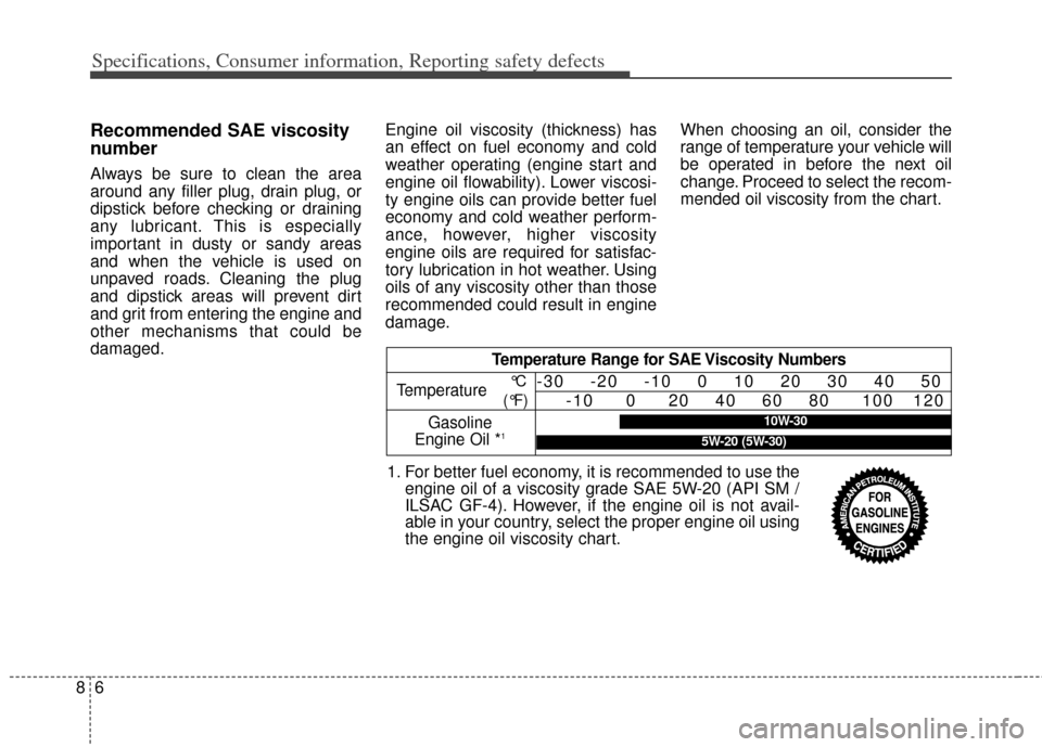
When choosing an oil, consider the
range of temperature your vehicle will
be operated in before the next oil
change. Proceed to select the recom-
mended oil viscosity from the chart.
Temperature Range for SAE Viscosity Numbers
Temperature
Gasoline
Engine Oil *
1
°C
(°F)-30 -20 -10 0 10 20 30 40 50 -10 0 20 40 60 80 100 120
1. For better fuel economy, it is recommended to use theengine oil of a viscosity grade SAE 5W-20 (API SM /
ILSAC GF-4). However, if the engine oil is not avail-
able in your country, select the proper engine oil using
the engine oil viscosity chart.
10W-30
5W-20 (5W-30)