Page 340 of 393
Maintenance
30
7
Turn the engine off and wait until it
cools down. Use extreme care when
removing the radiator cap. Wrap a
thick towel around it, and turn it
counterclockwise slowly to the first
stop. Step back while the pressure is
released from the cooling system.
When you are sure all the pressure
has been released, press down on
the cap, using a thick towel, and con-
tinue turning counterclockwise to
remove it.
Changing the coolant
Have the coolant changed by an
authorized Kia dealer according to
the Maintenance Schedule at the
beginning of this section.
Put a thick cloth around the radiator
cap before refilling the coolant in
order to prevent the coolant from
overflowing into engine parts such as
the alternator.CAUTION - Removing
radiator cap
Never attempt to
remove the radiator cap while the engineis operating or hot.Doing so might lead
to cooling system and engine damage.
Page 346 of 393
Maintenance
36
7
Front windshield wiper blade
1. Raise the wiper arm and turn the
wiper blade assembly to expose
the plastic locking clip. 2. Compress the clip and slide the
blade assembly downward.
3. Lift it off the arm. 4. Install the blade assembly in the
reverse order of removal.
1LDA50231JBA7037
CAUTION - Wiper arms
Do not allow the wiper arm tofall against the windshield,since it may chip or crack thewindshield.
1JBA7038
Page 350 of 393

Maintenance
40
7
When recharging the battery,
observe the following precautions:
The battery must be removed from
the vehicle and placed in an area
with good ventilation.
Watch the battery during charging, and stop or reduce the charging
rate if the battery cells begin
gassing (boiling) violently or if the
temperature of the electrolyte of
any cell exceeds 49°C (120°F).
Wear eye protection when check- ing the battery during charging.
Disconnect the battery charger in the following order.
1. Turn off the battery charger main switch.
2. Unhook the negative clamp from the negative battery terminal.
3. Unhook the positive clamp from the positive battery terminal.
Before performing maintenance or recharging the battery, turn off all
accessories and stop the engine.
The negative battery cable must be removed first and installed last
when the battery is disconnected.Reset items
Items should be reset after the bat-
tery has been discharged or the bat-
tery has been disconnected.
Sunroof (See section 4)
Climate control system (See section 4)
Clock (See section 4, Audio)
Audio (See section 4)
Page 355 of 393

745
Maintenance
Tire replacement
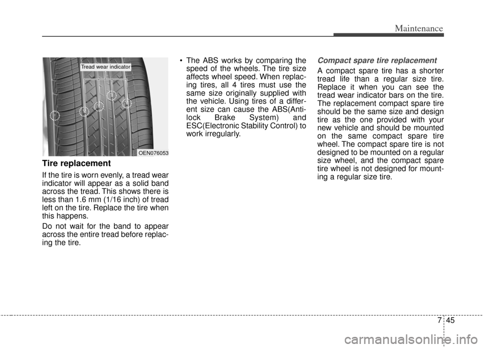
If the tire is worn evenly, a tread wear
indicator will appear as a solid band
across the tread. This shows there is
less than 1.6 mm (1/16 inch) of tread
left on the tire. Replace the tire when
this happens.
Do not wait for the band to appear
across the entire tread before replac-
ing the tire. The ABS works by comparing the
speed of the wheels. The tire size
affects wheel speed. When replac-
ing tires, all 4 tires must use the
same size originally supplied with
the vehicle. Using tires of a differ-
ent size can cause the ABS(Anti-
lock Brake System) and
ESC(Electronic Stability Control) to
work irregularly.
Compact spare tire replacement
A compact spare tire has a shorter
tread life than a regular size tire.
Replace it when you can see the
tread wear indicator bars on the tire.
The replacement compact spare tire
should be the same size and design
tire as the one provided with your
new vehicle and should be mounted
on the same compact spare tire
wheel. The compact spare tire is not
designed to be mounted on a regular
size wheel, and the compact spare
tire wheel is not designed for mount-
ing a regular size tire.
OEN076053
Tread wear indicator
Page 366 of 393
Maintenance
56
7
Memory fuse
Your vehicle is equipped with a mem-
ory fuse to prevent battery discharge
if your vehicle is parked without
being operated for prolonged peri-
ods. Use the following procedures
before parking the vehicle for pro-
longed periods.
1. Turn off the engine.
2. Turn off the headlights and tail
lights.
3. Open the driver’s side panel cover and pull out the memory fuse. If the memory fuse is pulled out
from the fuse panel, the warning
chime, audio, clock and interior
lamps, etc., will not operate. Some
items must be reset after replace-
ment. Refer to “Battery” in this sec-
tion.
Even when the memory fuse is pulled out, the battery can still be
discharged by operation of the
headlights or other electrical
devices.
Engine compartment fuse
replacement
1. Turn the ignition switch and all other switches off.
2. Remove the fuse panel cover by pressing the tab and pulling the
cover up.
OAM079022OAM072023
Page 369 of 393

759
Maintenance
Description Fuse ratingProtected component
P/WDW LH 25A Power Window Main Switch, Rear Power Window Switch LH
P/WDW RH 25A Power Window Main Switch, Passenger Power Window Switch, Rear Power Window Switch RH
PDM 2 10A PDM,Start/Stop Button Switch, Fob Holder
HAZARD 15A Hazard Relay, Hazard Switch, One Touch Flasher Unit
TAIL LP LH 10A Rear Combination Lamp LH, Head Lamp LH, License Lamp
TAIL LP RH 10ARear Combination Lamp RH, Head Lamp RH, Audio, Passenger Power Window Switch, Rheostat,
Power Window Main Switch, Hazard Switch, Instrument Cluster, Mood Lamp Switch,
AUX & USB Jack, ESC Switch, A/C Control Module, Multifunction Switch,
Driver/Passenger Seat Warmer Switch, ATM Shift Lever Indicator, Glove Box Lamp,
A/V & Navigation Head Unit, Telltale Lamp, ISG Switch, Active ECO Switch,
/V & Navigation Touch, AUX Jack
IG 2 10A BCM, Sunroof Motor
WIPER RR 15A Rear Wiper Relay, Rear Wiper Motor, Multifunction Switch (Wiper)
WIPER FRT 25A E/R Fuse & Relay Box (Wiper Relay), Front Wiper Motor, Multifunction Switch (Wiper)
AMP 25A AMP, ISG Low DC - DC Converter (AMP)
SUNROOF 20A Sunroof Motor
(FOG LP FRT) 15A Front Fog Lamp Relay
T/GATE OPEN 15A Tail Gate Relay, Data Link Connector, DRL Relay
(FOG LP RR) 10A -
A/CON 10AA/C Control Module, E/R Fuse & Relay Box (H/LP HI Relay, Blower Relay), Active Incar Sensor,
A/V & Navigation Touch
PDM 1 10A PDM
ACC 10AAudio, Mood Lamp Module, Power Outside Mirror Switch, Smart Key Control Module, PDM,
ATM Key Lock Control Module, A/V & Navigation Head Unit, BCM, AMP, A/V & Navigation Touch,
ISG Low DC - DC Converter (Audio/AMP)
C/LIGHTER 20A Cigarette Lighter, Rear Power Outlet
Page 370 of 393

Maintenance
60
7
Description Fuse rating Protected component
HTD MIRR 10A ECM/PCM, Driver/Passenger Power Outside Mirror, A/C Control Module, A/V & Navigation Touch
DR LOCK 20A Door Lock Relay, Door Unlock Relay, 2 Turn Lock Relay
STOP LP 15AStop Lamp Switch, Multipurpose Check Connector, HAC Relay, Stop Lamp Relay,
Sport Mode Switch, Key Solenoid
TCU 10AVehicle Speed Sensor (M/T), ATM Shift Lever Indicator, ATM Key Lock Control Module,
Transaxle Range Switch
ABS 10A ESC Module, ESC Switch, E/R Fuse & Relay Box (Multipurpose Check Connector)
IG 1 10ATire Pressure Monitoring Module, ISG Low DC - DC Converter (Audio/AMP),
Driver/Passenger Seat Warmer Switch, Driver/Passenger Seat Warmer, ISG Switch,
Electro Chromic Mirror, Oil Pump Invertor, Stop Lamp Switch, HAC Relay
P/OUTLET FRT 15A Front Power Outlet
A/BAG 15A SRS Control Module, Weight Classification Module, Telltale Lamp
IGN COIL 15A G4FD : Condenser, Ignition Coil #1 ~ #4
T/SIG 10A Hazard Switch, Multifunction Switch (Light)
CLUSTER 10A BCM, Instrument Cluster (IND.), A/C Control Module, Smart Key Control Module, PDM
ECU 10A ECM, PCM
START 10AE/R Fuse & Relay Box (Start Relay), PDM, Transaxle Range Switch, Ignition Lock Switch,
PCM/ECM
B/UP LP 10A Back-up Lamp Switch (M/T)
A/BAG IND 10A Instrument Cluster (Air Bag IND.)
POWER
CONNECTOR MODULE 15A
Audio, RF Receiver, A/V & Navigation Touch, ISG Low DC - DC Converter (Audio),
A/V & Navigation Head Unit
ROOM LP 10A BCM, Instrument Cluster (IND.), A/C Control Module, Tire Pressure Monitoring Module,
Center Room Lamp, Luggage Lamp,
Overhead Console Assembly (Map Lamp), Ignition Key ILL. & Door Warning Switch,
Vanity Lamp LH/RH
Page 372 of 393

Maintenance
62
7
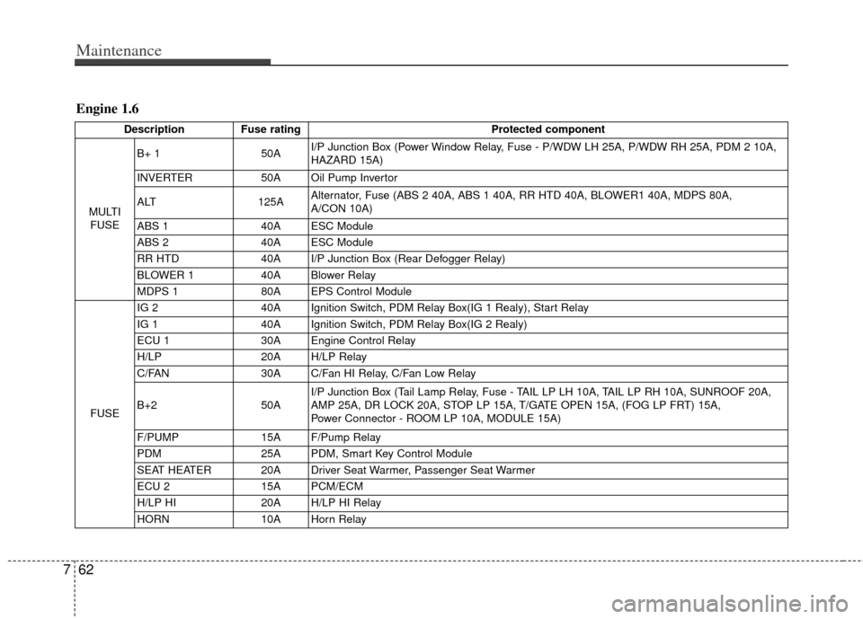
Engine 1.6
Description Fuse rating Protected component
MULTI FUSE B+ 1
50AI/P Junction Box (Power Window Relay, Fuse - P/WDW LH 25A, P/WDW RH 25A, PDM 2 10A,
HAZARD 15A)
INVERTER 50A Oil Pump Invertor
ALT 125AAlternator, Fuse (ABS 2 40A, ABS 1 40A, RR HTD 40A, BLOWER1 40A, MDPS 80A,
A/CON 10A)
ABS 1 40A ESC Module
ABS 2 40A ESC Module
RR HTD 40A I/P Junction Box (Rear Defogger Relay)
BLOWER 1 40A Blower Relay
MDPS 1 80A EPS Control Module
FUSE IG 2
40A Ignition Switch, PDM Relay Box(IG 1 Realy), Start Relay
IG 1 40A Ignition Switch, PDM Relay Box(IG 2 Realy)
ECU 1 30A Engine Control Relay
H/LP 20A H/LP Relay
C/FAN 30A C/Fan HI Relay, C/Fan Low Relay
B+2 50AI/P Junction Box (Tail Lamp Relay, Fuse - TAIL LP LH 10A, TAIL LP RH 10A, SUNROOF 20A,
AMP 25A, DR LOCK 20A, STOP LP 15A, T/GATE OPEN 15A, (FOG LP FRT) 15A,
Power Connector - ROOM LP 10A, MODULE 15A)
F/PUMP 15A F/Pump Relay
PDM 25A PDM, Smart Key Control Module
SEAT HEATER 20A Driver Seat Warmer, Passenger Seat Warmer
ECU 2 15A PCM/ECM
H/LP HI 20A H/LP HI Relay
HORN 10A Horn Relay