Page 337 of 371

Maintenance
50
7
FUSES
A vehicle’s electrical system is protected
from electrical overload damage by
fuses.
This vehicle has 3 fuse panels, one locat-
ed in the driver’s side panel bolster, the
other in the engine compartment.
If any of your vehicle’s lights, acces-
sories, or controls do not work, check the
appropriate circuit fuse. If a fuse has
blown, the element inside the fuse willmelt.
If the electrical system does not work,
first check the driver’s side fuse panel.
Always replace a blown fuse with one of
the same rating.
If the replacement fuse blows, this indi-
cates an electrical problem. Avoid using
the system involved and immediately
consult an authorized HYUNDAI dealer.
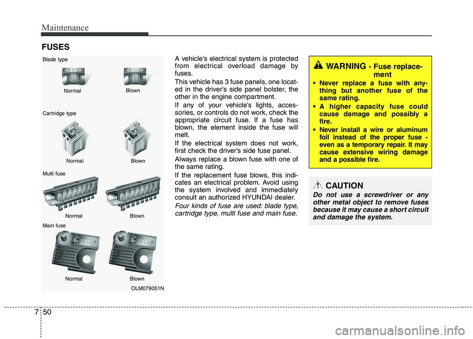
Four kinds of fuse are used: blade type,cartridge type, multi fuse and main fuse.
WARNING - Fuse replace-
ment
Never replace a fuse with any- thing but another fuse of the same rating.
A higher capacity fuse could cause damage and possibly a
fire.
Never install a wire or aluminum foil instead of the proper fuse -
even as a temporary repair. It may
cause extensive wiring damage
and a possible fire.
CAUTION
Do not use a screwdriver or any
other metal object to remove fusesbecause it may cause a short circuit
and damage the system.
OLM079051N
Normal
Normal
Blade type
Cartridge type Multi fuse Main fuse Blown
Blown
Normal Blown
Normal Blown
Page 338 of 371
751
Maintenance
Instrument panel fuse replace- ment
1. Turn the ignition switch and all otherswitches off.
2. Open the fuse panel cover. 3. Pull the suspected fuse straight out.
Use the removal tool provided in the fuse panel.
4. Check the removed fuse; replace it if it is blown.
Spare fuses are provided in the instru-
ment panel fuse panel (or in the enginecompartment fuse panel).
5. Push in a new fuse of the same rating, and make sure it fits tightly in the clips.
If it fits loosely, consult an authorized
HYUNDAI dealer.
If you do not have a spare, use a fuse of the same rating from a circuit you maynot need for operating the vehicle, such as the cigarette lighter fuse.
If the headlights or other electrical com-
ponents do not work and the fuses are
OK, check the fuse panel in the engine
compartment. If a fuse is blown, it mustbe replaced.
OLM079020OLM079021N
Page 339 of 371

Maintenance
52
7
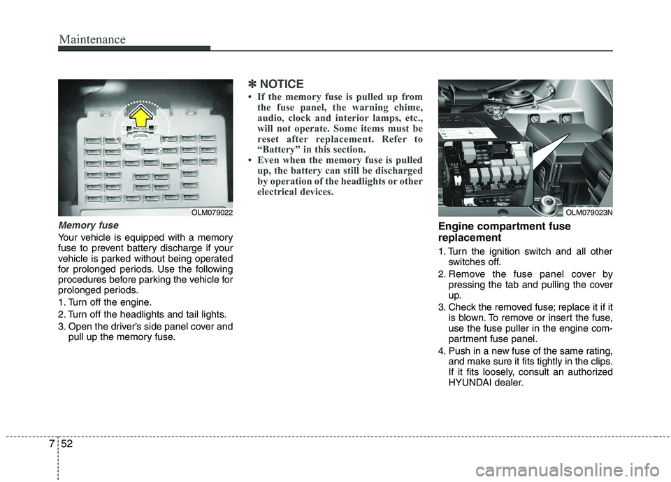
Memory fuse
Your vehicle is equipped with a memory
fuse to prevent battery discharge if your
vehicle is parked without being operated
for prolonged periods. Use the following
procedures before parking the vehicle for
prolonged periods.
1. Turn off the engine.
2. Turn off the headlights and tail lights.
3. Open the driver’s side panel cover and
pull up the memory fuse.
✽✽ NOTICE
If the memory fuse is pulled up from the fuse panel, the warning chime,
audio, clock and interior lamps, etc.,
will not operate. Some items must be
reset after replacement. Refer to
“Battery” in this section.
Even when the memory fuse is pulled
up, the battery can still be discharged
by operation of the headlights or other
electrical devices.
Engine compartment fuse replacement
1. Turn the ignition switch and all other switches off.
2. Remove the fuse panel cover by pressing the tab and pulling the cover
up.
3. Check the removed fuse; replace it if it is blown. To remove or insert the fuse,use the fuse puller in the engine com-
partment fuse panel.
4. Push in a new fuse of the same rating, and make sure it fits tightly in the clips.
If it fits loosely, consult an authorized
HYUNDAI dealer.
OLM079023NOLM079022
Page 340 of 371
753
Maintenance
Main fuse and Multi fuse
If the main fuse and Multi fuse is blown,
it must be removed as follows:
1. Disconnect the negative battery cable.
2. Remove the nuts shown in the pictureabove.
3. Replace the fuse with a new one of the same rating.
4. Reinstall in the reverse order of removal.
✽✽ NOTICE
If the main fuse is blown, consult an
authorized HYUNDAI dealer.CAUTION
After checking the fuse panel in the engine compartment, securelyinstall the fuse panel cover. If not,
electrical failures may occur fromwater contact.
OLM079052N
Page 341 of 371
Maintenance
54
7
✽✽
NOTICE
Not all fuse panel descriptions in this
manual may be applicable to your vehi-
cle. It is accurate at the time of printing.
When you inspect the fuse panel in your
vehicle, refer to the fuse panel label.Instrument panel fuse panel Engine compartment fuse panel
OLM079026/OLM079027N/OLM079053N
Fuse/relay panel description
Inside the fuse/relay panel covers, you can find the fuse/relay label describing fuse/relay name and capacity.
Page 344 of 371

757
Maintenance
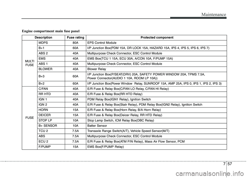
Engine compartment main fuse panel
Description Fuse ratingProtected component
MULTI FUSE MDPS 80A EPS Control Module
B+1 60A I/P Junction Box(PDM 15A, DR LOCK 15A, HAZARD 15A, IPS 4, IPS 5, IPS 6, IPS 7)
ABS 2 40A Multipurpose Check Connector, ESC Control Module
EMS 40A EMS Box(TCU 1 15A, ECU 30A, A/CON 10A, F/PUMP 15A)
ABS 1 40A Multipurpose Check Connector, ESC Control Module
BLOWER 40A Blower Relay
B+3 60A
I/P Junction Box(P/SEAT(DRV) 20A, SAFETY POWER WINDOW 20A, TPMS 7.5A,
Power Connector(AUDIO 1 10A, ROOM LP 10A))
B+2 60A I/P Junction Box(Power Window Relay, SUNROOF 15A, AMP 25A, IPS 0, IPS 1, IPS 2, IPS 3)
FUSE C/FAN 40A E/R Fuse & Relay Box(C/FAN LO Relay, C/FAN HI Relay)
RR HTD 40A E/R Fuse & Relay Box(RR HTD Relay)
IGN 1 40A PDM Relay Box(IGN1 Relay), Ignition Switch
IGN 2 40A E/R Fuse & Relay Box(Statr Relay), PDM Relay Box(IGN2 Relay), Ignition Switch
HORN 15A E/R Fuse & Relay Box(Horn Relay, B/A Horn Relay)
DEICER 15A E/R Fuse & Relay Box(Deicer Relay, RR HTD Relay)
STOP LP 10A Stop Lamp Switch, ICM Relay Box(DBC Relay)
B+ SENSOR 10A Batter Sensor
TCU 2 7.5A Transaxle Range Switch(A/T), Vehicle Speed Sensor(M/T)
ABS 7.5A Multipurpose Check Connector, ESC Control Module
ECU 2 7.5A E/R Fuse & Relay Box(ATM P/N Relay), Mass Air Flow Sensor, PCM
F/PUMP 15A EMS Box(F/PUMP Relay)
Page 345 of 371
Maintenance
58
7
Description Fuse rating Protected component
FUSE SENSOR 4 15A
E/R Fuse & Relay Box(C/FAN HI, LO Relay), EMS Box(F/PUMP Relay),
Oxygen Sensor (UP, DOWN), PCM
SENSOR 3 10A EMS Box(A/CON Relay), Injector(#1, #2, #3, #4)
SENSOR 2 10A -
TCU 1 15A PCM
A/CON 10A EMS Box(A/CON Relay)
SENSOR 1 10A Crankshaft Position Sensor, Camshaft Position Sensor #1/2, Oil Control Valve #1/2,
Canister Purge Control Solenoid Valve, Variable Intake Manifold Valve, Canister Close Valve
ECU 1 20A Ignition Colil (#1, #2, #3, #4), Condenser
ECU 30A EMS Box(Engine Control Relay)
Page 354 of 371

767
Maintenance
Waxing
A good coat of wax is a barrier between
your paint and contaminate. Keeping a
good coat of wax on your vehicle will help protect it.
Wax the vehicle when water will no longer bead on the paint.
Always wash and dry the vehicle before
waxing. Use a good quality liquid or
paste wax, and follow the manufacturer’s
instructions. Wax all metal trim to protect
it and to maintain its luster.
Removing oil, tar, and similar materials
with a spot remover will usually strip the
wax from the finish. Be sure to re-wax
these areas even if the rest of the vehicle
does not yet need waxing.Finish damage repair
Deep scratches or stone chips in the
painted surface must be repaired
promptly. Exposed metal will quickly rust
and may develop into a major repair
expense.
✽✽NOTICE
If your vehicle is damaged and requires
any metal repair or replacement, be sure
the body shop applies anti-corrosion
materials to the parts repaired or
replaced.
CAUTION
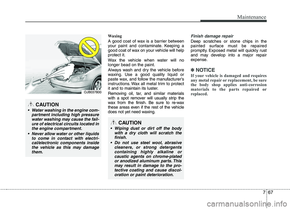
Water washing in the engine com- partment including high pressurewater washing may cause the fail-
ure of electrical circuits located inthe engine compartment.
Never allow water or other liquids to come in contact with electri-cal/electronic components insidethe vehicle as this may damage them.
CAUTION
Wiping dust or dirt off the body
with a dry cloth will scratch thefinish.
Do not use steel wool, abrasive cleaners, or strong detergentscontaining highly alkaline orcaustic agents on chrome-platedor anodized aluminum parts. This
may result in damage to the pro-tective coating and cause discol-oration or paint deterioration.
OJB037800