Page 224 of 403
Driving your vehicle
25
WARNING- ENGINE EXHAUST CAN BE DANGEROUS!
Engine exhaust fumes can be extremely dangerous. If, at any time, you smell exhaust fumes inside the vehicle, open the win-
dows immediately.
• Do not inhale exhaust fumes.Exhaust fumes contain carbon monoxide, a colorless, odorless gas that can cause unconsciousness and death by asphyxia-
tion.
The exhaust system should be checked whenever the vehicle is raised to change the oil or for any other purpose. If you hear
a change in the sound of the exhaust or if you drive over something that strikes the underneath side of the car, have the
exhaust system checked as soon as possible by an authorized HYUNDAI dealer.
Letting the engine idle in your garage, even with the garage door open, is a hazardous practice. Never run the engine in your
garage any longer than it takes to start the vehicle and back the car out.
If it is necessary to idle the engine for a prolonged period with people inside the car, be sure to do so only in an open area
with the air intake set at "Fresh" and fan operating at one of the higher speeds so fresh air is drawn into the interior.
If you must drive with the trunk lid open because you are carrying objects that make this necessary:
1. Close all windows.
2. Open side vents.
3. Set the air intake control at "Fresh", the air flow control at "Floor" or "Face" and the fan at one of the higher speeds.
To assure proper operation of the ventilation system, be sure the ventilation air intakes located just in front of the windshie ld are
kept clear of snow, ice, leaves or other obstructions.
Page 271 of 403
65
What to do in an emergency
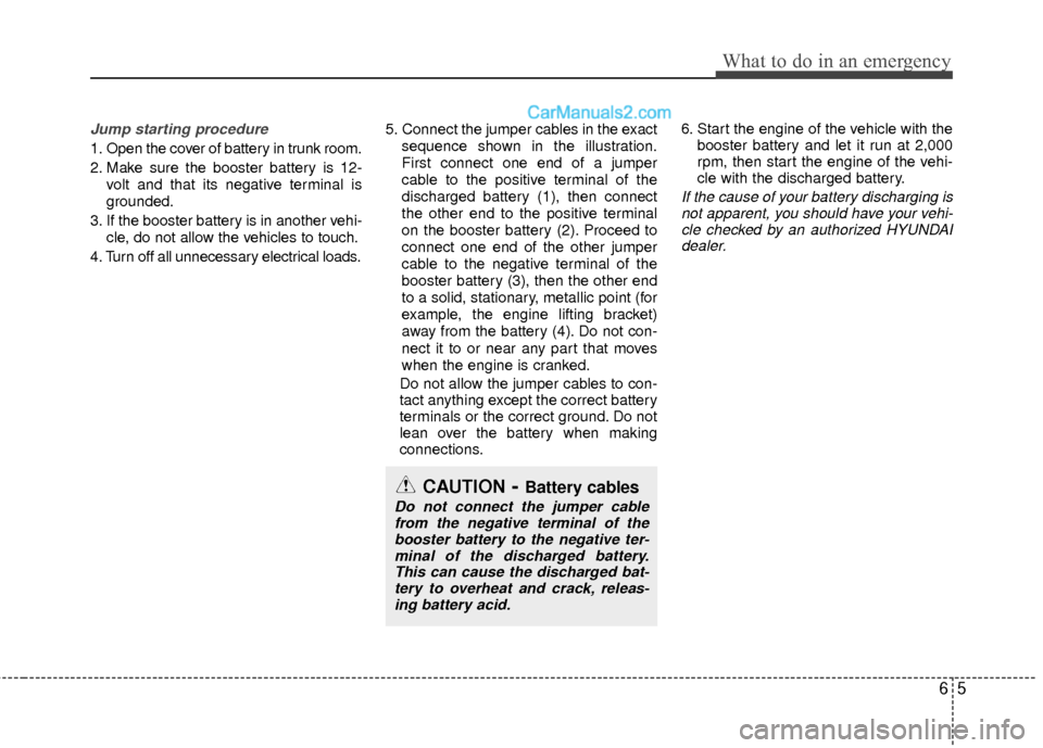
Jump starting procedure
1. Open the cover of battery in trunk room.
2. Make sure the booster battery is 12-volt and that its negative terminal is
grounded.
3. If the booster battery is in another vehi- cle, do not allow the vehicles to touch.
4. Turn off all unnecessary electrical loads. 5. Connect the jumper cables in the exact
sequence shown in the illustration.
First connect one end of a jumper
cable to the positive terminal of the
discharged battery (1), then connect
the other end to the positive terminal
on the booster battery (2). Proceed to
connect one end of the other jumper
cable to the negative terminal of the
booster battery (3), then the other end
to a solid, stationary, metallic point (for
example, the engine lifting bracket)
away from the battery (4). Do not con-
nect it to or near any part that moves
when the engine is cranked.
Do not allow the jumper cables to con-
tact anything except the correct battery
terminals or the correct ground. Do not
lean over the battery when making
connections. 6. Start the engine of the vehicle with the
booster battery and let it run at 2,000
rpm, then start the engine of the vehi-
cle with the discharged battery.
If the cause of your battery discharging isnot apparent, you should have your vehi-cle checked by an authorized HYUNDAI dealer.
CAUTION- Battery cables
Do not connect the jumper cablefrom the negative terminal of the booster battery to the negative ter-minal of the discharged battery.This can cause the discharged bat-tery to overheat and crack, releas- ing battery acid.
Page 327 of 403
Maintenance
34
7
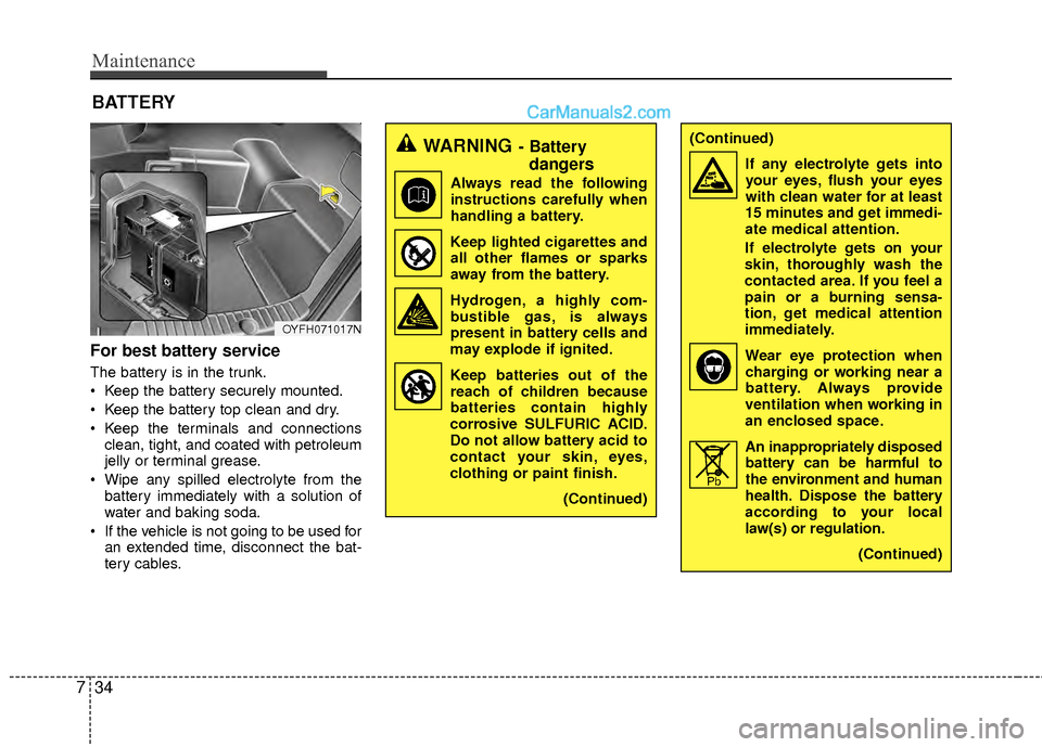
For best battery service
The battery is in the trunk.
Keep the battery securely mounted.
Keep the battery top clean and dry.
Keep the terminals and connections
clean, tight, and coated with petroleum
jelly or terminal grease.
Wipe any spilled electrolyte from the battery immediately with a solution of
water and baking soda.
If the vehicle is not going to be used for an extended time, disconnect the bat-
tery cables.
BATTERY
OYFH071017N
WARNING- Battery dangers
Always read the following
instructions carefully when
handling a battery.
Keep lighted cigarettes and all other flames or sparks
away from the battery.
Hydrogen, a highly com- bustible gas, is always
present in battery cells and
may explode if ignited.
Keep batteries out of the reach of children because
batteries contain highly
corrosive SULFURIC ACID.
Do not allow battery acid to
contact your skin, eyes,
clothing or paint finish.
(Continued)
(Continued)If any electrolyte gets intoyour eyes, flush your eyes
with clean water for at least
15 minutes and get immedi-
ate medical attention.
If electrolyte gets on your
skin, thoroughly wash the
contacted area. If you feel a
pain or a burning sensa-
tion, get medical attention
immediately.
Wear eye protection whencharging or working near a
battery. Always provide
ventilation when working in
an enclosed space.
An inappropriately disposed battery can be harmful to
the environment and human
health. Dispose the battery
according to your local
law(s) or regulation.
(Continued)
Pb
Page 348 of 403

755
Maintenance
Inner fuse panel (Driver’s side fuse panel)
DescriptionFuse rating Protected component
P/SEAT DRI 30A Driver Manual Switch
AMP 30A JBL AMP, AMP
TRUNK 10A I/P Junction Box (Trunk Lid Relay), Fuel Filler Door & Trunk Lid Switch
SAFETY POWER WINDOW 25A Safety Power Window Module
P/WDW LH 25A Power Window Main Switch, Rear Power Window Switch LH
MODULE HEV 7.5A Low DC Converter, Hybrid Inverter, BMS Control Module
BMS 10A BMS Control Module
START 2 7.5A Fob Holder, Start Stop Button Switch, PDM, Stop Lamp Switch, Smart Key Module
MODULE 3 7.5AE/R Fuse & Relay Box (AUX Water Pump Relay), Sport Mode Switch, Key Solenoid,
Active Air Flap
P/WDW RH 25A Power Window Main Switch, Rear Power Window Switch RH
HTD MIRR 10A Driver Power Outside Mirror, Passenger Power Outside Mirror
P/SEAT ASST 20A Passenger Power Seat
S/HEATER FRT 15A Driver Seat Warmer Module, Passenger Seat Warmer Module
PDM 25A PDM
CLOCK 10ASmart Key Module, PDM, BCM, Front Monitor, Clock, Rear Camera Module,
A/V & Navigation Head Unit, Audio, Overhead Console Lamp, AMP, JBL AMP,
Power Outside Mirror Switch
A/CON 7.5A E/R Fuse & Relay Box (Blower Relay), A/C Control Module
S/HTR RR 20A Rear Seat Warmer Switch LH, Rear Seat Warmer Switch RH
SUN ROOF 20A Panorama Sunroof
POWER OUTLET 1 15A Front Power Outlet RH
MODULE 2 7.5A Rear Camera Module, BCM
Spare 20A -
Page 349 of 403
Maintenance
56
7
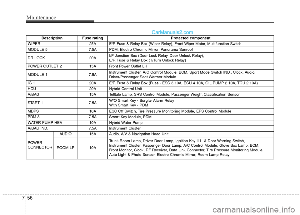
Description Fuse rating Protected component
WIPER 25A E/R Fuse & Relay Box (Wiper Relay), Front Wiper Motor, Multifunction Switch
MODULE 5 7.5A PDM, Electro Chromic Mirror, Panorama Sunroof
DR LOCK 20AI/P Junction Box (Door Lock Relay, Door Unlock Relay),
E/R Fuse & Relay Box (T/Turn Unlock Relay)
POWER OUTLET 2 15A Front Power Outlet LH
MODULE 1 7.5AInstrument Cluster, A/C Control Module, BCM, Sport Mode Switch IND., Clock, Audio,
Driver/Passenger Seat Warmer Module
IG 1 20A E/R Fuse & Relay Box (Fuse - ESC 3 10A, ECU 4 10A, OIL PUMP 2 10A, TCU 2 10A)
HCU 20A Hybrid Control Unit
A/BAG 15A Telltale Lamp, SRS Control Module, Passenger Weight Classification Sensor
START 1 7.5AW/O Smart Key - Burglar Alarm Relay
With Smart Key - PDM
MDPS 10A ESC Off Switch, Tire Pressure Monitoring Module, EPS Control Module
PDM 3 7.5A Smart Key Module, PDM
WATER PUMP HEV 10A Hybrid Water Pump
A/BAG IND. 7.5A Instrument Cluster
POWER
CONNECTOR AUDIO 15A Audio, A/V & Navigation Head Unit
ROOM LP 10A Trunk Room Lamp, Driver Door Lamp, Ignition Key ILL. & Door Warning Switch,
Instrument Cluster, Passenger Door Lamp, A/C Control Module, Glove Box Lamp, BCM,
Front Monitor, Clock, RF Receiver, Data Link Connector, Tire Pressure Monitoring Module,
Auto Light & Photo Sensor, Electro Chromic Mirror, Room Lamp Relay
Page 350 of 403

757
Maintenance
Engine compartment main fuse panel
Description Fuse ratingProtected component
MULTI FUSE B+3
60AI/P Junction Box (Power Window Relay, Fuse - TRUNK 10, S/HEATER FRT 15A,
SAFETY POWER WINDOW 25A, MODULE 3 7.5A, PDM 25A, Power Connector - AUDIO 15A)
IG 1 40A Smart Key - IG 1 Relay, ACC Relay
EMS 40A EMS Box (Fuse - HORN 15A, ECU 3 10A, ECU 1 30A, F/PUMP 20A)
RR HTD 40A RR HTD Relay
BLOWER 40A Blower Relay
B+4 60AI/P Junction Box (Fuse - P/SEAT DRI 30A, AMP 30A, START 2 7.5A, BMS 10A, IPS 2, IPS 3,
IPS 5, IPS 8)
MDPS 80A EPS Control Module
C/FAN LO 40A C/FAN LO Relay
FUSE B+2
50AI/P Junction Box (Fuse - SUNROOF 20A, DR LOCK, IPS 1, IPS 4, IPS 6, IPS 7, IPS 9,
Power Connector - ROOM LP 10A)
WIPER 10A PCM
RR HTD IND 10A A/C Control Module LDC 10A Low DC Converter, Hybrid Inverter
BMS C/FAN 15A BMS Blower Motor Relay TCU 1 20A PCU
STOP LP 15A Stop Lamp Relay, HAC Relay DEICER 20A Deicer Relay ECU 2 20A PCUHCU 20A Hybrid Control
IG 2 30A Smart Key - IG 2 Relay
AHB 1 40A AHB Control Module
OIL PUMP 1 20A Electric Oil Pump Unit
Page 357 of 403
Maintenance
64
7
Side repeater light bulb replace-
ment (if equipped)
If the light bulb is not operating, have the
vehicle checked by an authorized
HYUNDAI dealer.
Rear combination light bulb
replacement
(1) Stop and tail light
(2) Rear turn signal light
(3) Tail light or stop and tail light
(4) Back-up light
(5) Light curtain (Tail light)
(6) Side marker
Rear turn signal
1. Open the trunk lid.
2. Remove the service cover by pulling out
the service cover.
OYF079042N
OYFH071043N
OYFH071035NOYF079041
Page 358 of 403
765
Maintenance
3. Remove the socket from the assemblyby turning the socket counterclockwise
until the tabs on the socket align with
the slots on the assembly.
4. Remove the bulb from the socket by pressing it in and rotating it counter-
clockwise until the tabs on the bulb
align with the slots in the socket. Pull
the bulb out of the socket.
5. Insert a new bulb by inserting it into the socket and rotating it until it locks
into place.
6. Install the socket in the assembly by aligning the tabs on the socket with the
slots in the assembly. Push the socket
into the assembly and turn the socket
clockwise.
7. Install the service cover by putting it into the service hole.
Tail light, stop and tail light,side marker, light curtain
If the light is not operating, have the vehi-
cle checked by an authorized HYUNDAI
dealer.
1. Open the trunk lid.
2. Remove the service cover by pulling out the service cover.
3. Remove the socket from the assembly by turning the socket counterclockwise
until the tabs on the socket align with
the slots on the assembly.
4. Remove the bulb from the socket by pressing it in and rotating it counter-
clockwise until the tabs on the bulb
align with the slots in the socket. Pull
the bulb out of the socket. 5. Insert a new bulb by inserting it into
the socket and rotating it until it locks
into place.
6. Install the socket in the assembly by aligning the tabs on the socket with the
slots in the assembly. Push the socket
into the assembly and turn the socket
clockwise.
7. Install the service cover by putting it into the service hole.
OYFH071087N