2012 Hyundai Sonata Hybrid ECO mode
[x] Cancel search: ECO modePage 14 of 403
17
Introduction
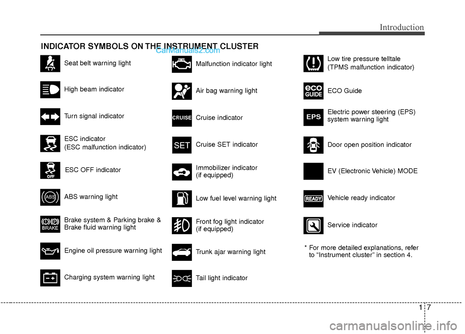
INDICATOR SYMBOLS ON THE INSTRUMENT CLUSTER
Seat belt warning light
High beam indicator
Turn signal indicator
ABS warning light
Brake system & Parking brake &
Brake fluid warning light
Engine oil pressure warning light
Malfunction indicator light
Air bag warning light
Cruise indicator
Cruise SET indicator
Immobilizer indicator
(if equipped)
Low fuel level warning light* For more detailed explanations, referto “Instrument cluster” in section 4.
Charging system warning lightTail light indicator
Trunk ajar warning light
Front fog light indicator
(if equipped)
Door open position indicator Low tire pressure telltale
(TPMS malfunction indicator)
ECO Guide
Electric power steering (EPS)
system warning light
EPS
ESC indicator
(ESC malfunction indicator)
ESC OFF indicator
Vehicle ready indicator EV (Electronic Vehicle) MODE
Service indicator
Page 38 of 403
319
Safety features of your vehicle
Seat belts - Front passenger and rearseat 3-point system with combinationlocking retractor
To fasten your seat belt:
Combination retractor type seat belts are
installed in the rear seat positions to help
accommodate the installation of child
restraint systems. Although a combina-
tion retractor is also installed in the front
passenger seat position, it is strongly
recommended that children always be
seated in the rear seat. NEVER place
any infant restraint system in the front
seat of the vehicle.
This type of seat belt combines the fea-
tures of both an emergency locking
retractor seat belt and an automatic lock-
ing retractor seat belt. To fasten your seat
belt, pull it out of the retractor and insert
the metal tab into the buckle. There will
be an audible "click" when the tab locks
into the buckle. When not securing a
child restraint, the seat belt operates in
the same way as the driver's seat belt
(Emergency Locking Retractor Type). It
automatically adjusts to the proper length
only after the lap belt portion of the seat
belt is adjusted manually so that it fits
snugly around your hips. When the seat belt is fully extended from
the retractor to allow the installation of a
child restraint system, the seat belt oper-
ation changes to allow the belt to retract,
but not to extend (Automatic Locking
Retractor Type). Refer to “Using a child
restraint system” in this section.
✽ ✽
NOTICE
Although the combination retractor
provides the same level of protection for
seated passengers in either emergency
or automatic locking modes, it is recom-
mended that seated passengers use the
emergency locking feature for improved
convenience. The automatic locking
function is intended to facilitate child
restraint installation. To convert from
the automatic locking feature to the
emergency locking operation mode,
allow the unbuckled seat belt to fully
retract.
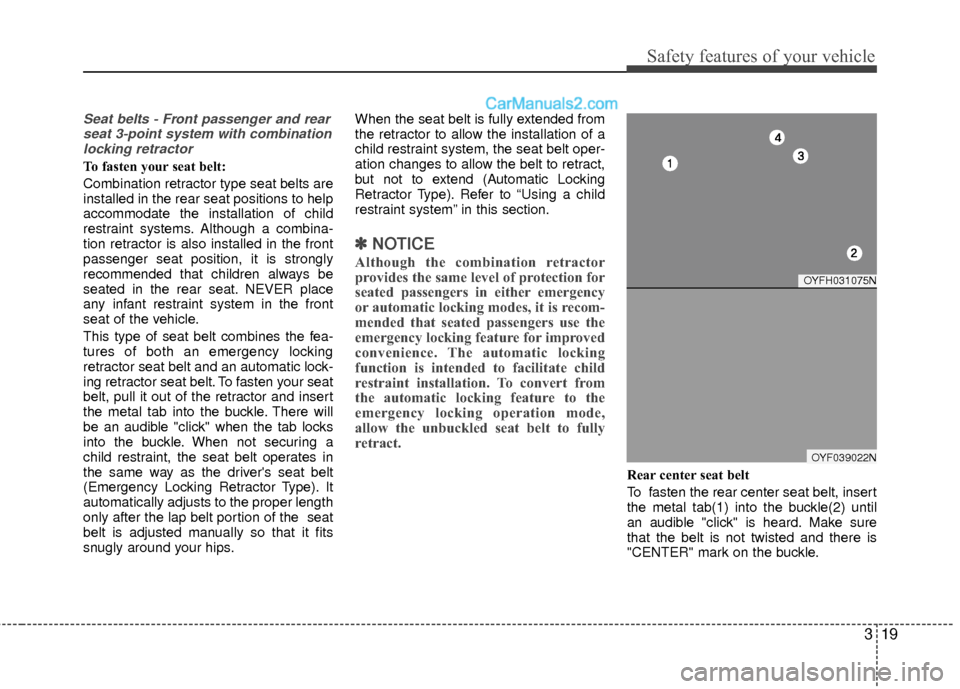
Rear center seat belt
To fasten the rear center seat belt, insert
the metal tab(1) into the buckle(2) until
an audible "click" is heard. Make sure
that the belt is not twisted and there is
"CENTER" mark on the buckle.
OYFH031075N
OYF039022N
Page 48 of 403
329
Safety features of your vehicle
For safety reasons, we recommend that
the child restraint system be used in the
rear seats.
Since all passenger seat belts move
freely under normal conditions and only
lock under extreme or emergency condi-
tions (emergency locking mode), you
must manually change these seat belts
to the automatic locking mode to secure
a child restraint.
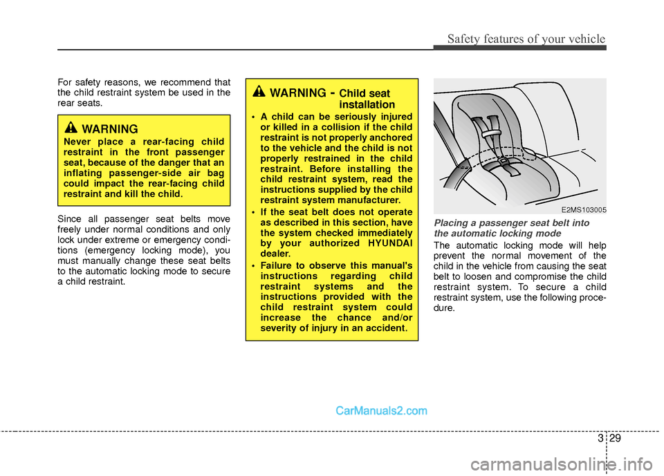
Placing a passenger seat belt intothe automatic locking mode
The automatic locking mode will help
prevent the normal movement of the
child in the vehicle from causing the seat
belt to loosen and compromise the child
restraint system. To secure a child
restraint system, use the following proce-
dure.
WARNING- Child seat
installation
A child can be seriously injured or killed in a collision if the child
restraint is not properly anchored
to the vehicle and the child is not
properly restrained in the child
restraint. Before installing the
child restraint system, read the
instructions supplied by the child
restraint system manufacturer.
If the seat belt does not operate as described in this section, have
the system checked immediately
by your authorized HYUNDAI
dealer.
Failure to observe this manual's instructions regarding child
restraint systems and the
instructions provided with the
child restraint system could
increase the chance and/or
severity of injury in an accident.
WARNING
Never place a rear-facing child
restraint in the front passenger
seat, because of the danger that an
inflating passenger-side air bag
could impact the rear-facing child
restraint and kill the child.
E2MS103005
Page 115 of 403
Features of your vehicle
34
4
To adjust the Zone setting:
1. Determine the desired Zone Number
based upon your current location on
the Zone Map.
2. Press and hold the button for more than 3 but less than 6 seconds, the
current Zone Number will appear on
the display.
3. Pressing and holding the button again will cause the numbers to incre-
ment (Note: they will repeat …13, 14,
15, 1, 2, …). Releasing the button
when the desired Zone Number
appears on the display will set the new
Zone.
4. Within about 5 seconds the compass will start displaying a compass head-
ing again.
There are some conditions that can
cause changes to the vehicle magnets,
such as installing a ski rack or a CB
antenna. Body repair work on the vehicle
can also cause changes to the vehicle's
magnetic field. In these situations, the
compass will need to be re-calibrated to
quickly correct for these changes. To re-
calibrate the compass: 1. Press and hold the button for more
than 6 seconds. When the compass
memory is cleared a "C" will appear in
the display.
2. To calibrate the compass, drive the vehicle in 2 complete circles at less
than 5 mph (8 km/h).
Integrated HomeLink
®Wireless Control
System
The HomeLink® Wireless Control
System provides a convenient way to
replace up to three hand-held radio-fre-
quency (RF) transmitters with a single
built-in device. This innovative feature will
learn the radio frequency codes of most
current transmitters to operate devices
such as gate operators, garage door
openers, entry door locks, security sys-
tems, even home lighting. Both standard
and rolling code-equipped transmitters
can be programmed by following the out-
lined procedures. Additional HomeLink
®
information can be found at: www.home-
link.com or by calling 1-800-355-3515. Retain the original transmitter of the RF
device you are programming for use in
other vehicles as well as for future
HomeLink
®programming. It is also sug-
gested that upon the sale of the vehicle,
the programmed HomeLink
®buttons be
erased for security purposes.
CAUTION
Before programming HomeLink®to
a garage door opener or gate oper- ator, make sure that people and objects are out of the way of thedevice to prevent potential harm ordamage. Do not use HomeLink
®
with any garage door opener thatlacks the safety stop and reverse features required by U.S. federalsafety standards (this includes any garage door opener model manu-factured before April 1, 1982). Agarage door that cannot detect anobject - signaling the door to stop and reverse - does not meet currentU.S. federal safety standards. Using a garage door opener without thesefeatures increases the risk of seri- ous injury or death.
Page 118 of 403
437
Features of your vehicle
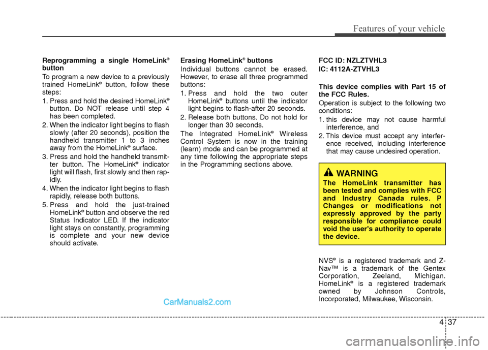
Reprogramming a single HomeLink®
button
To program a new device to a previously
trained HomeLink
®button, follow these
steps:
1. Press and hold the desired HomeLink
®
button. Do NOT release until step 4
has been completed.
2. When the indicator light begins to flash slowly (after 20 seconds), position the
handheld transmitter 1 to 3 inches
away from the HomeLink
®surface.
3. Press and hold the handheld transmit- ter button. The HomeLink
®indicator
light will flash, first slowly and then rap-
idly.
4. When the indicator light begins to flash rapidly, release both buttons.
5. Press and hold the just-trained HomeLink
®button and observe the red
Status Indicator LED. If the indicator
light stays on constantly, programming
is complete and your new device
should activate. Erasing HomeLink
®buttons
Individual buttons cannot be erased.
However, to erase all three programmed
buttons:
1. Press and hold the two outer HomeLink
®buttons until the indicator
light begins to flash-after 20 seconds.
2. Release both buttons. Do not hold for longer than 30 seconds.
The Integrated HomeLink
®Wireless
Control System is now in the training
(learn) mode and can be programmed at
any time following the appropriate steps
in the Programming sections above. FCC ID: NZLZTVHL3
IC: 4112A-ZTVHL3
This device complies with Part 15 of
the FCC Rules.
Operation is subject to the following two
conditions:
1. this device may not cause harmful
interference, and
2. This device must accept any interfer- ence received, including interference
that may cause undesired operation.
NVS
®is a registered trademark and Z-
Nav™ is a trademark of the Gentex
Corporation, Zeeland, Michigan.
HomeLink
®is a registered trademark
owned by Johnson Controls,
Incorporated, Milwaukee, Wisconsin.
WARNING
The HomeLink transmitter has
been tested and complies with FCC
and Industry Canada rules. P
Changes or modifications not
expressly approved by the party
responsible for compliance could
void the user's authority to operate
the device.
Page 121 of 403

Features of your vehicle
40
4
INSTRUMENT CLUSTER
1. EV MODE
2. Turn signal indicators
3. Speedometer
4. Engine temperature gauge
5. Warning and indicator lights
6. Fuel gauge
7. Trip computer
8. ECO guide
9. Odometer
10. Ready
* The actual cluster in the vehicle may
differ from the illustration.
For more details refer to the "Gauges"
section in the next pages.
OYFH041040N
Page 126 of 403
445
Features of your vehicle
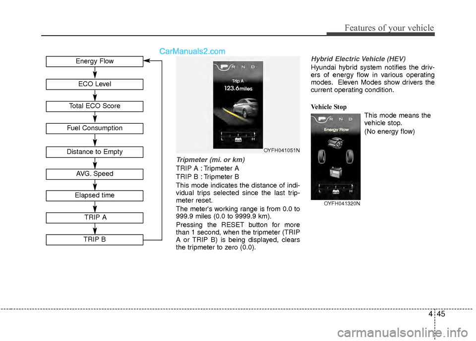
Tripmeter (mi. or km)
TRIP A : Tripmeter A
TRIP B : Tripmeter B
This mode indicates the distance of indi-
vidual trips selected since the last trip-
meter reset.
The meter's working range is from 0.0 to
999.9 miles (0.0 to 9999.9 km).
Pressing the RESET button for more
than 1 second, when the tripmeter (TRIP
A or TRIP B) is being displayed, clears
the tripmeter to zero (0.0).
Hybrid Electric Vehicle (HEV)
Hyundai hybrid system notifies the driv-
ers of energy flow in various operating
modes. Eleven Modes show drivers the
current operating condition.
Vehicle StopThis mode means the
vehicle stop.
(No energy flow)
OYFH041051NDistance to Empty
Fuel Consumption
Energy Flow
ECO Level
Total ECO Score
AVG. Speed
Elapsed time
TRIP A
TRIP B
OYFH041320N
Page 128 of 403
447
Features of your vehicle
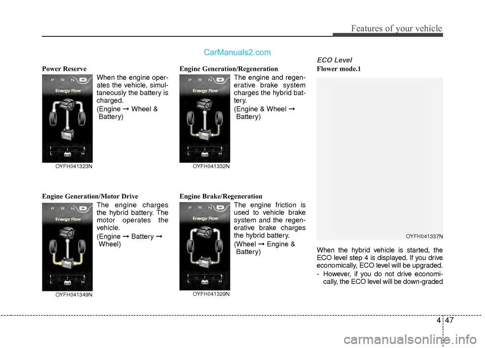
Power ReserveWhen the engine oper-
ates the vehicle, simul-
taneously the battery is
charged.
(Engine ➞ Wheel &
Battery)
Engine Generation/Motor Drive The engine charges
the hybrid battery. The
motor operates the
vehicle.
(Engine ➞Battery ➞
Wheel) Engine Generation/Regeneration
The engine and regen-
erative brake system
charges the hybrid bat-
tery.
(Engine & Wheel ➞Battery)
Engine Brake/Regeneration The engine friction is
used to vehicle brake
system and the regen-
erative brake charges
the hybrid battery.
(Wheel ➞Engine &
Battery)
ECO Level
Flower mode.1
When the hybrid vehicle is started, the
ECO level step 4 is displayed. If you drive
economically, ECO level will be upgraded.
- However, if you do not drive economi- cally, the ECO level will be down-graded
OYFH041349N
OYFH041323N
OYFH041329N
OYFH041332N
OYFH041337N