2012 HYUNDAI IX35 display
[x] Cancel search: displayPage 312 of 560
What to do in an emergency
20
6
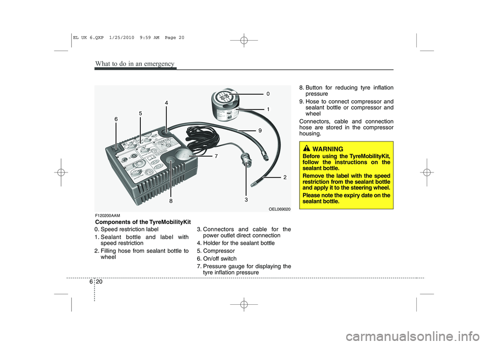
0. Speed restriction label
1. Sealant bottle and label with
speed restriction
2. Filling hose from sealant bottle to wheel 3. Connectors and cable for the
power outlet direct connection
4. Holder for the sealant bottle
5. Compressor
6. On/off switch
7. Pressure gauge for displaying the tyre inflation pressure 8. Button for reducing tyre inflation
pressure
9. Hose to connect compressor and sealant bottle or compressor and wheel
Connectors, cable and connectionhose are stored in the compressorhousing.
WARNING
Before using the TyreMobilityKit,
follow the instructions on the
sealant bottle.
Remove the label with the speed
restriction from the sealant bottle
and apply it to the steering wheel.
Please note the expiry date on the
sealant bottle.
F120200AAM
Components of the TyreMobilityKit
OEL069020
EL UK 6.QXP 1/25/2010 9:59 AM Page 20
Page 356 of 560
Maintenance
36
7
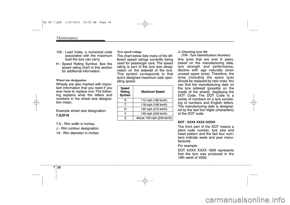
S 112 mph (180 km/h)
T 118 mph (190 km/h)
H 130 mph (210 km/h)
V 149 mph (240 km/h) Z Above 149 mph (240 km/h)
Maximum Speed
Speed
Rating
Symbol
102 - Load Index, a numerical code
associated with the maximum
load the tyre can carry.
H - Speed Rating Symbol. See the speed rating chart in this section
for additional information.
Wheel size designation
Wheels are also marked with impor-
tant information that you need if you
ever have to replace one. The follow-
ing explains what the letters and
numbers in the wheel size designa-tion mean.
Example wheel size designation: 7.0JX18
7.0 - Rim width in inches. J - Rim contour designation.
18 - Rim diameter in inches. Tyre speed ratings
The chart below lists many of the dif-
ferent speed ratings currently being
used for passenger cars. The speed
rating is part of the tyre size desig-
nation on the sidewall of the tyre.This symbol corresponds to that
tyre's designed maximum safe oper-ating speed.3. Checking tyre life
(TIN : Tyre Identification Number)
Any tyres that are over 6 years,
based on the manufacturing date,
tyre strength and performance,
decline with age naturally (even
unused spare tyres). Therefore, thetyres (including the spare tyre)
should be replaced by new ones. You
can find the manufacturing date on
the tyre sidewall (possibly on the
inside of the wheel), displaying the
DOT Code. The DOT Code is a
series of numbers on a tyre consist-
ing of numbers and English letters.
The manufacturing date is designat-
ed by the last four digits (characters)
of the DOT code.
DOT : XXXX XXXX OOOO
The front part of the DOT means a
plant code number, tyre size and
tread pattern and the last four num-
bers indicate week and year manu-
factured.
For example:
DOT XXXX XXXX 1609 represents
that the tyre was produced in the
16th week of 2009.
EL UK 7.QXP 1/25/2010 10:03 AM Page 36
Page 405 of 560
Index
4
I
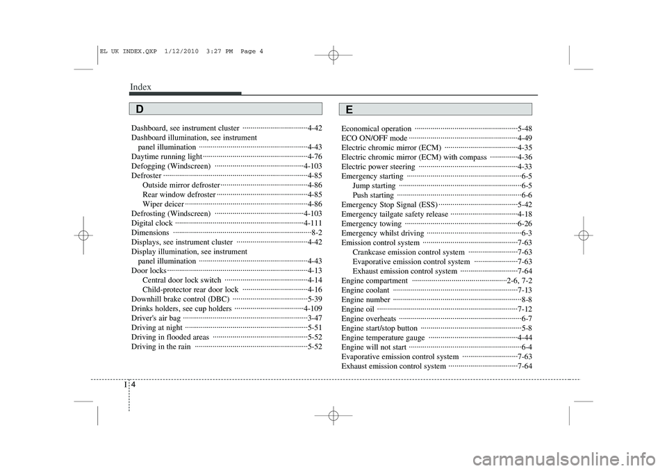
Dashboard, see instrument cluster ·································4-42 Dashboard illumination, see instrument
panel illumination ·······················································4-43
Daytime running light ·····················································4-76
Defogging (Windscreen) ·············································4-103
Defroster ·········································································4-85 Outside mirror defroster ············································4-86
Rear window defroster ··············································4-85
Wiper deicer ······························································4-86
Defrosting (Windscreen) ·············································4-103
Digital clock ·································································4-111Dimensions ······································································8-2
Displays, see instrument cluster ····································4-42Display illumination, see instrument panel illumination ·······················································4-43
Door locks ·······································································4-13 Central door lock switch ··········································4-14
Child-protector rear door lock ·································4-16
Downhill brake control (DBC) ······································5-39
Drinks holders, see cup holders ···································4-109
Driver's air bag ·······························································3-47
Driving at night ······························································5-51
Driving in flooded areas ················································5-52
Driving in the rain ·························································5-52 Economical operation ····················································5-48
ECO ON/OFF mode ·······················································4-49
Electric chromic mirror (ECM) ·····································4-35
Electric chromic mirror (ECM) with compass ··············4-36
Electric power steering ··················································4-33
Emergency starting ··························································6-5
Jump starting ······························································6-5
Push starting ·······························································6-6
Emergency Stop Signal (ESS) ········································5-42Emergency tailgate safety release ··································4-18
Emergency towing ·························································6-26
Emergency whilst driving ················································6-3
Emission control system ················································7-63 Crankcase emission control system ·························7-63
Evaporative emission control system ······················7-63
Exhaust emission control system ·····························7-64
Engine compartment ················································2-6, 7-2
Engine coolant ·······························································7-13
Engine number ·································································8-8
Engine oil ·······································································7-12
Engine overheats ······························································6-7
Engine start/stop button ···················································5-8
Engine temperature gauge ·············································4-44
Engine will not start ·························································6-4
Evaporative emission control system ····························7-63
Exhaust emission control system ···································7-64
ED
EL UK INDEX.QXP 1/12/2010 3:27 PM Page 4
Page 448 of 560
Features of your vehicle
36
4
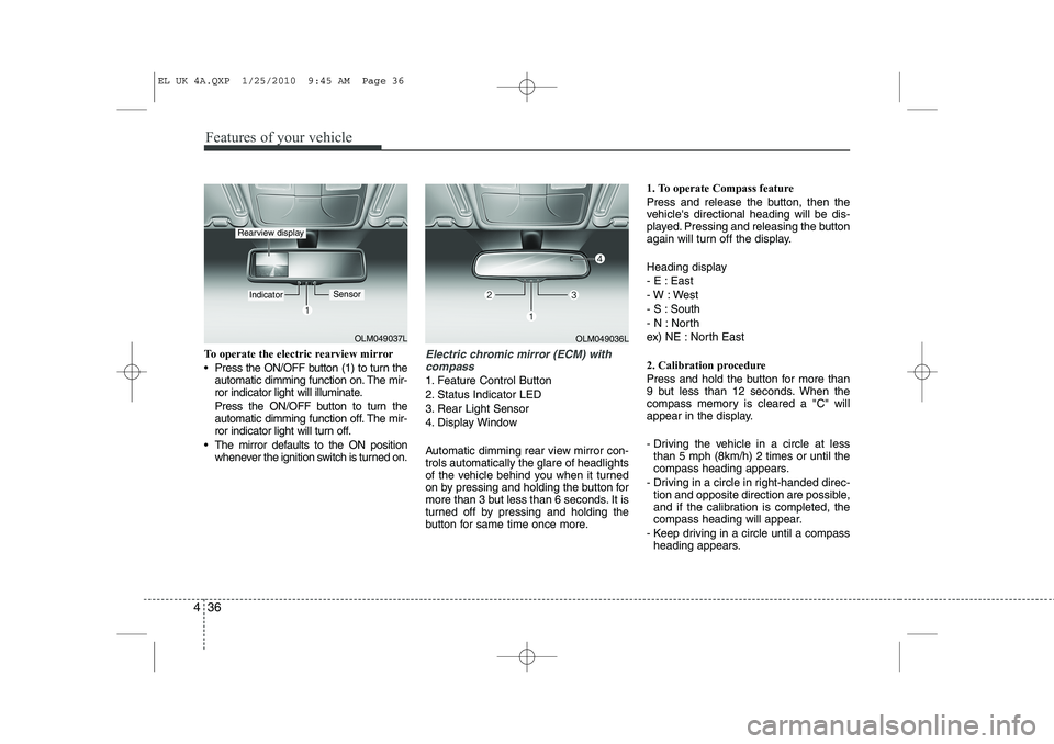
To operate the electric rearview mirror
Press the ON/OFF button (1) to turn the
automatic dimming function on. The mir-
ror indicator light will illuminate.
Press the ON/OFF button to turn the
automatic dimming function off. The mir-
ror indicator light will turn off.
The mirror defaults to the ON position whenever the ignition switch is turned on.Electric chromic mirror (ECM) with
compass
1. Feature Control Button
2. Status Indicator LED
3. Rear Light Sensor
4. Display Window
Automatic dimming rear view mirror con- trols automatically the glare of headlights
of the vehicle behind you when it turned
on by pressing and holding the button for
more than 3 but less than 6 seconds. It is
turned off by pressing and holding the
button for same time once more. 1. To operate Compass feature
Press and release the button, then the
vehicle's directional heading will be dis-
played. Pressing and releasing the button
again will turn off the display.
Heading display
- E : East
- W : West
- S : South
- N : North
ex) NE : North East
2. Calibration procedure
Press and hold the button for more than
9 but less than 12 seconds. When the
compass memory is cleared a "C" will
appear in the display.
- Driving the vehicle in a circle at less
than 5 mph (8km/h) 2 times or until the
compass heading appears.
- Driving in a circle in right-handed direc- tion and opposite direction are possible,
and if the calibration is completed, the
compass heading will appear.
- Keep driving in a circle until a compass heading appears.
OLM049037L
IndicatorSensor
Rearview display
OLM049036L
EL UK 4A.QXP 1/25/2010 9:45 AM Page 36
Page 450 of 560
Features of your vehicle
38
4
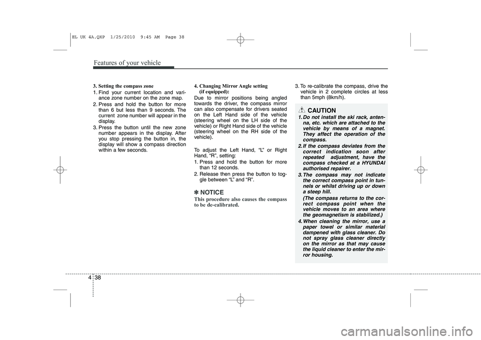
3. Setting the compass zone
1. Find your current location and vari-
ance zone number on the zone map.
2. Press and hold the button for more than 6 but less than 9 seconds. The
current zone number will appear in the
display.
3. Press the button until the new zone number appears in the display. After
you stop pressing the button in, the
display will show a compass direction
within a few seconds. 4. Changing Mirror Angle setting
(if equipped):
Due to mirror positions being angled
towards the driver, the compass mirror
can also compensate for drivers seated
on the Left Hand side of the vehicle
(steering wheel on the LH side of the
vehicle) or Right Hand side of the vehicle
(steering wheel on the RH side of the
vehicle).
To adjust the Left Hand, “L” or Right
Hand, “R”, setting:
1. Press and hold the button for more than 12 seconds.
2. Release then press the button to tog- gle between “L” and “R”.
✽✽ NOTICE
This procedure also causes the compass to be de-calibrated.
3. To re-calibrate the compass, drive the vehicle in 2 complete circles at less than 5mph (8km/h).
CAUTION
1. Do not install the ski rack, anten-
na, etc. which are attached to thevehicle by means of a magnet. They affect the operation of thecompass.
2. If the compass deviates from the correct indication soon afterrepeated adjustment, have the compass checked at a HYUNDAI
authorised repairer.
3. The compass may not indicate the correct compass point in tun-nels or whilst driving up or downa steep hill.
(The compass returns to the cor-rect compass point when thevehicle moves to an area wherethe geomagnetism is stabilized.)
4. When cleaning the mirror, use a paper towel or similar materialdampened with glass cleaner. Do not spray glass cleaner directlyon the mirror as that may cause the liquid cleaner to enter the mir-
ror housing.
EL UK 4A.QXP 1/25/2010 9:45 AM Page 38
Page 457 of 560
445
Features of your vehicle
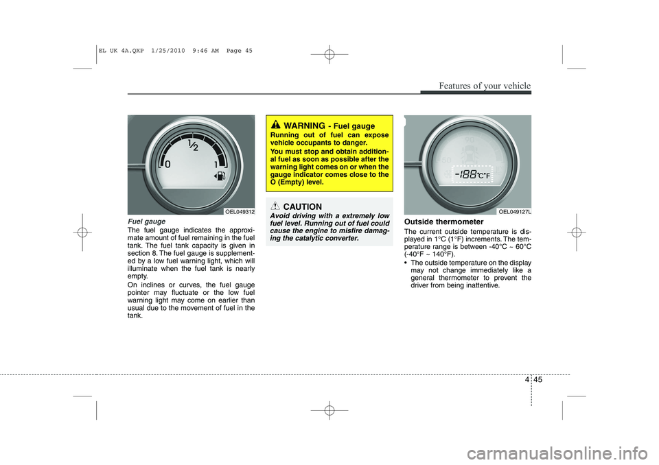
Fuel gauge
The fuel gauge indicates the approxi- mate amount of fuel remaining in the fuel
tank. The fuel tank capacity is given in
section 8. The fuel gauge is supplement-
ed by a low fuel warning light, which will
illuminate when the fuel tank is nearly
empty.
On inclines or curves, the fuel gauge
pointer may fluctuate or the low fuel
warning light may come on earlier than
usual due to the movement of fuel in thetank.Outside thermometer
The current outside temperature is dis-
played in 1°C (1°F) increments. The tem-
perature range is between -40°C ~ 60°C(-40°F ~ 140°F).
The outside temperature on the display
may not change immediately like a
general thermometer to prevent the
driver from being inattentive.
WARNING - Fuel gauge
Running out of fuel can expose
vehicle occupants to danger.
You must stop and obtain addition-
al fuel as soon as possible after thewarning light comes on or when the
gauge indicator comes close to the
O (Empty) level.
CAUTION
Avoid driving with a extremely low fuel level. Running out of fuel could cause the engine to misfire damag-ing the catalytic converter. OEL049312OEL049127L
EL UK 4A.QXP 1/25/2010 9:46 AM Page 45
Page 458 of 560
Features of your vehicle
46
4
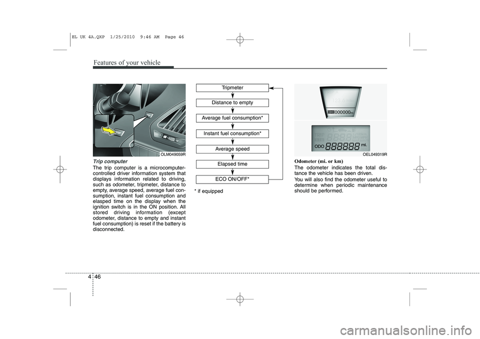
Trip computer
The trip computer is a microcomputer-
controlled driver information system that
displays information related to driving,
such as odometer, tripmeter, distance to
empty, average speed, average fuel con-sumption, instant fuel consumption and
elasped time on the display when the
ignition switch is in the ON position. All
stored driving information (except
odometer, distance to empty and instant
fuel consumption) is reset if the battery isdisconnected. Odometer (mi. or km) The odometer indicates the total dis-
tance the vehicle has been driven.
You will also find the odometer useful to
determine when periodic maintenance
should be performed.
Tripmeter
Average speed
Elapsed time
Distance to empty
Average fuel consumption*
Instant fuel consumption*
* if equipped
OEL049319R
ECO ON/OFF*OLM049059R
EL UK 4A.QXP 1/25/2010 9:46 AM Page 46
Page 459 of 560
447
Features of your vehicle
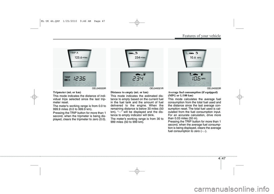
Tripmeter (mi. or km) This mode indicates the distance of indi-
vidual trips selected since the last trip-meter reset.
The meter's working range is from 0.0 to 999.9 miles (0.0 to 999.9 km).
Pressing the TRIP button for more than 1
second, when the tripmeter is being dis-
played, clears the tripmeter to zero (0.0).Distance to empty (mi. or km) This mode indicates the estimated dis- tance to empty based on the current fuelin the fuel tank and the amount of fuel
delivered to the engine. When the
remaining distance is below 30 miles (50
km), “---” will be displayed and the dis-
tance to empty indicator will blink.
The meter’s working range is from 30 to 999 miles (50 to 999 km).Average fuel consumption (if equipped)(MPG or L/100 km)
This mode calculates the average fuel consumption from the total fuel used and
the distance since the last average con-
sumption reset. The total fuel used is cal-culated from the fuel consumption input.
For an accurate calculation, drive morethan 0.03 miles (50 m).
Pressing the TRIP button for more than 1
second, when the average fuel consump-
tion is being displayed, clears the average
fuel consumption to zero (--.-).
OEL049321ROEL049323ROEL049320R
EL UK 4A.QXP 1/25/2010 9:46 AM Page 47