Page 175 of 217

6
DO-IT-YOURSELF MAINTENANCE
23
CAUTION:
When replacing a fusible link, never use anything but a new fusible link with the same or lower amperagerating. Never use a piece of wire or a higher-rated fusible link. This could result in serious damage andcreate a fire hazard.!
!WARNING:
Never install a wire or aluminum foil instead of the proper fuse - even as a temporary repair. It may cause ex- tensive wiring damage and a pos-sible fire.NOTE:
o To replace a fusible link, first tilt the driver's seatback forward. (Re- fer to "To Inspect the Engine Com-partment Under the Driver's Seat" on page 1-12.)
o To open the fuse box cover, press the hook of the cover and pull upthe cover. G200A02HR
G200B01HR-GAT Replacing Accessory Fuse The fuse box for the lights and other electrical accessories will be found lowon the dashboard on the driver's side. Inside the box you will find a list show- ing the circuits protected by each fuse.If any of your car's lights or other electrical accessories stop working, a blown fuse could be the reason. If thefuse has burned out, you will see that the metal strip inside the fuse has burned through. If you suspect a blownfuse, follow this procedure:
1. Turn off the ignition and all other
switches. HHR4003
Page 177 of 217
6
DO-IT-YOURSELF MAINTENANCE
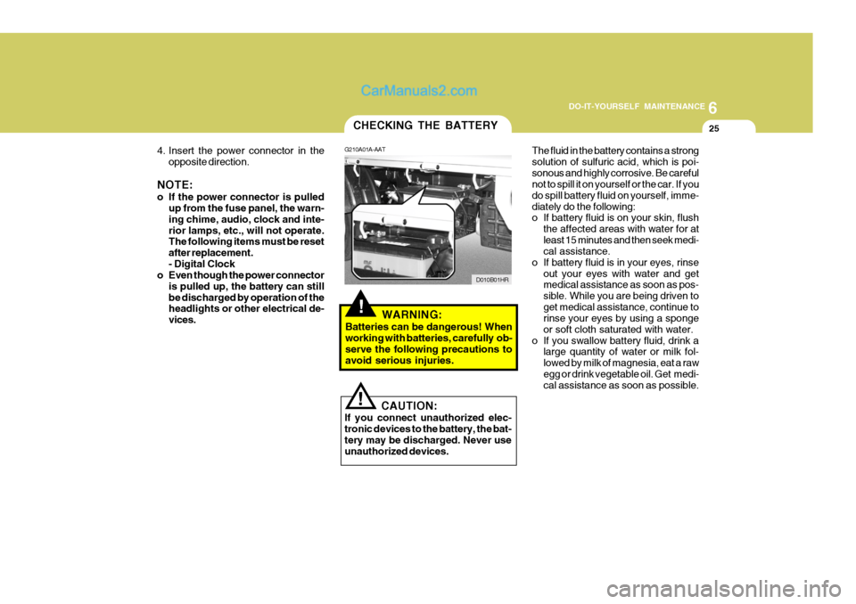
25CHECKING THE BATTERY
G210A01A-AAT
D010B01HR
4. Insert the power connector in the
opposite direction.
NOTE:
o If the power connector is pulled up from the fuse panel, the warn- ing chime, audio, clock and inte-rior lamps, etc., will not operate. The following items must be reset after replacement.- Digital Clock
o Even though the power connector
is pulled up, the battery can stillbe discharged by operation of the headlights or other electrical de- vices.
!WARNING:
Batteries can be dangerous! When working with batteries, carefully ob-serve the following precautions to avoid serious injuries. The fluid in the battery contains a strong solution of sulfuric acid, which is poi-sonous and highly corrosive. Be careful not to spill it on yourself or the car. If you do spill battery fluid on yourself, imme-diately do the following:
o If battery fluid is on your skin, flush
the affected areas with water for at least 15 minutes and then seek medi- cal assistance.
o If battery fluid is in your eyes, rinse out your eyes with water and getmedical assistance as soon as pos- sible. While you are being driven toget medical assistance, continue to rinse your eyes by using a sponge or soft cloth saturated with water.
o If you swallow battery fluid, drink a large quantity of water or milk fol-lowed by milk of magnesia, eat a rawegg or drink vegetable oil. Get medi- cal assistance as soon as possible.
! CAUTION:
If you connect unauthorized elec- tronic devices to the battery, the bat-tery may be discharged. Never use unauthorized devices.
Page 180 of 217
6 DO-IT-YOURSELF MAINTENANCE
28
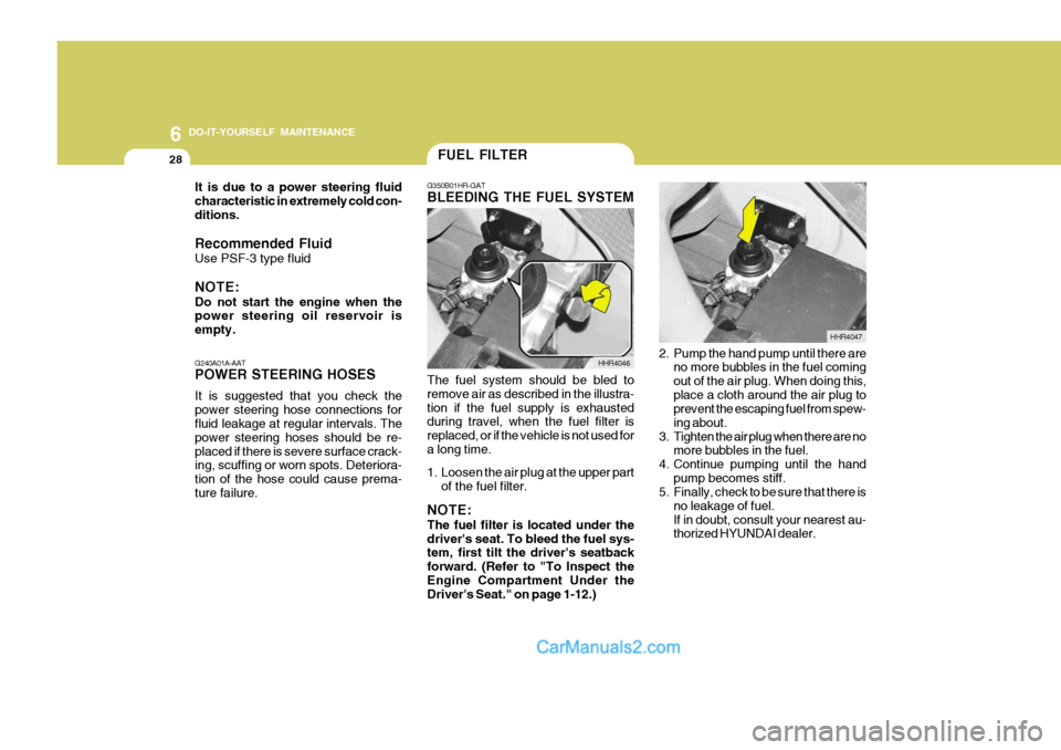
G350B01HR-GAT BLEEDING THE FUEL SYSTEM
The fuel system should be bled to remove air as described in the illustra-tion if the fuel supply is exhausted during travel, when the fuel filter is replaced, or if the vehicle is not used fora long time.
1. Loosen the air plug at the upper part of the fuel filter.
NOTE: The fuel filter is located under the driver's seat. To bleed the fuel sys- tem, first tilt the driver's seatback forward. (Refer to "To Inspect theEngine Compartment Under the Driver's Seat." on page 1-12.) HHR4046
2. Pump the hand pump until there are
no more bubbles in the fuel coming out of the air plug. When doing this,place a cloth around the air plug to prevent the escaping fuel from spew- ing about.
3. Tighten the air plug when there are no more bubbles in the fuel.
4. Continue pumping until the hand
pump becomes stiff.
5. Finally, check to be sure that there is
no leakage of fuel.If in doubt, consult your nearest au- thorized HYUNDAI dealer. HHR4047
FUEL FILTER
G240A01A-AAT POWER STEERING HOSES It is suggested that you check the power steering hose connections for fluid leakage at regular intervals. The power steering hoses should be re-placed if there is severe surface crack- ing, scuffing or worn spots. Deteriora- tion of the hose could cause prema-ture failure.
It is due to a power steering fluidcharacteristic in extremely cold con-ditions. Recommended Fluid Use PSF-3 type fluid NOTE: Do not start the engine when the power steering oil reservoir is empty.
Page 182 of 217
6 DO-IT-YOURSELF MAINTENANCE
30
!WARNING:
o Do not smoke or have any other open flame near the vehicle while bleeding the fuel system.
o Be sure to carefully wipe away any
water drained out in this manner,because the fuel mixed in the wa- ter might be ignited and result in a fire.
HEADLIGHT AIMING ADJUSTMENT
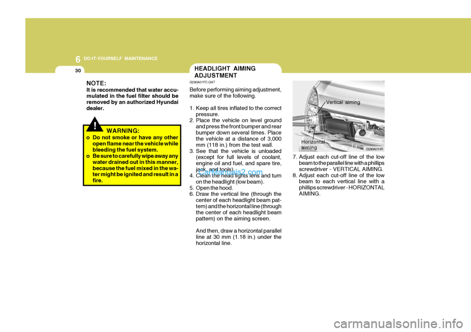
7. Adjust each cut-off line of the lowbeam to the parallel line with a phillips screwdriver - VERTICAL AIMING.
8. Adjust each cut-off line of the low beam to each vertical line with a phillips screwdriver - HORIZONTALAIMING. G290A01HR
Horizontal aiming
Vertical aiming
G290A01FC-GAT Before performing aiming adjustment, make sure of the following.
1. Keep all tires inflated to the correct
pressure.
2. Place the vehicle on level ground
and press the front bumper and rear bumper down several times. Place the vehicle at a distance of 3,000 mm (118 in.) from the test wall.
3. See that the vehicle is unloaded (except for full levels of coolant,engine oil and fuel, and spare tire,jack, and tools).
4. Clean the head lights lens and turn
on the headlight (low beam).
5. Open the hood.
6. Draw the vertical line (through the
center of each headlight beam pat- tern) and the horizontal line (through the center of each headlight beam pattern) on the aiming screen. And then, draw a horizontal parallel line at 30 mm (1.18 in.) under thehorizontal line.
NOTE: It is recommended that water accu- mulated in the fuel filter should be removed by an authorized Hyundaidealer.
Page 183 of 217
6
DO-IT-YOURSELF MAINTENANCE
31REPLACEMENT OF LIGHT BULBS
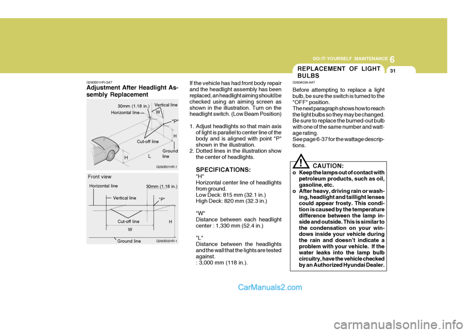
If the vehicle has had front body repair and the headlight assembly has been replaced, an headlight aiming should be checked using an aiming screen asshown in the illustration. Turn on the headlight switch. (Low Beam Position)
1. Adjust headlights so that main axis of light is parallel to center line of the body and is aligned with point "P"shown in the illustration.
2. Dotted lines in the illustration show
the center of headlights. SPECIFICATIONS: "H" Horizontal center line of headlights from ground.Low Deck: 815 mm (32.1 in.) High Deck: 820 mm (32.3 in.) "W" Distance between each headlight center : 1,330 mm (52.4 in.) "L" Distance between the headlightsand the wall that the lights are tested against. : 3,000 mm (118 in.). G260A03A-AAT Before attempting to replace a light bulb, be sure the switch is turned to the "OFF" position. The next paragraph shows how to reachthe light bulbs so they may be changed. Be sure to replace the burned-out bulb with one of the same number and watt-age rating. See page 6-37 for the wattage descrip- tions.
CAUTION:
o Keep the lamps out of contact with petroleum products, such as oil,gasoline, etc.
o After heavy, driving rain or wash- ing, headlight and taillight lensescould appear frosty. This condi-tion is caused by the temperature difference between the lamp in- side and outside. This is similar tothe condensation on your win- dows inside your vehicle during the rain and doesn’t indicate aproblem with your vehicle. If the water leaks into the lamp bulb circuitry, have the vehicle checkedby an Authorized Hyundai Dealer.
!
G290B01HR-GAT Adjustment After Headlight As- sembly Replacement
G290B01HR-1
H
Ground line
30mm (1.18 in.)
Vertical line
L
Cut-off line "P"
Horizontal line
G290B02HR-1
30mm (1.18 in.)
Front view
Horizontal line
Vertical line
Cut-off lineH
W H
W
Ground line
"P"
Page 193 of 217
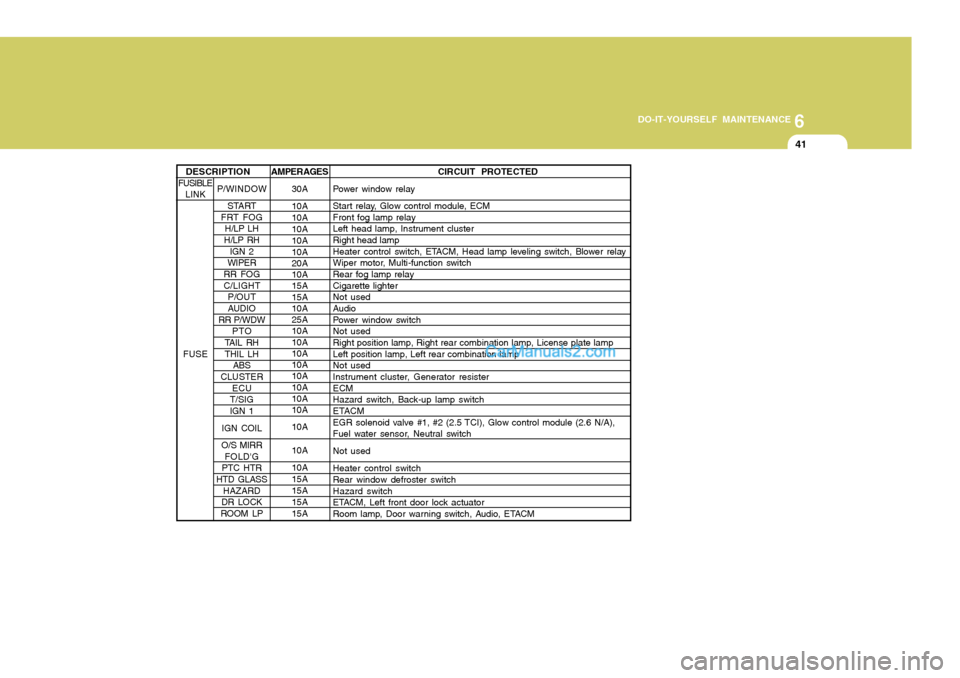
6
DO-IT-YOURSELF MAINTENANCE
41
AMPERAGES 30A 10A 10A10A 10A 10A 20A 10A 15A 15A 10A 25A 10A 10A 10A 10A 10A 10A 10A 10A 10A 10A 10A 15A15A15A15A CIRCUIT PROTECTED
Power window relay
Start relay, Glow control module, ECM Front fog lamp relayLeft head lamp, Instrument cluster Right head lamp
Heater control switch, ETACM, Head lamp leveling switch, Blower relay
Wiper motor, Multi-function switch Rear fog lamp relay Cigarette lighterNot used Audio
Power window switchNot used Right position lamp, Right rear combination lamp, License plate lamp Left position lamp, Left rear combination lampNot used
Instrument cluster, Generator resister ECMHazard switch, Back-up lamp switch
ETACM
EGR solenoid valve #1, #2 (2.5 TCI), Glow control module (2.6 N/A),
Fuel water sensor, Neutral switch Not usedHeater control switch Rear window defroster switch Hazard switch
ETACM, Left front door lock actuator
Room lamp, Door warning switch, Audio, ETACM
P/WINDOW START
FRT FOG
H/LP LH
H/LP RH IGN 2
WIPER
RR FOG C/LIGHT P/OUT
AUDIO
RR P/WDW
PTO
TAIL RH THIL LH ABS
CLUSTER ECU
T/SIG IGN 1
IGN COIL
O/S MIRR FOLD'G
PTC HTR
HTD GLASS HAZARD
DR LOCK
ROOM LP
DESCRIPTION
FUSIBLE LINK
FUSE
Page 208 of 217
9 VEHICLE SPECIFICATIONS
2
1st 2nd3rd 4th 5thReverse
Double Cab
��� � ��
Standard Cab
4,795 1,740 1,9652,430 1,485 1,320 High Deck
Standard Cab ��� � �
1,420
TypeWheel Free PlayRack Stroke Oil Pump Type
Rack and pinion 0 ~ 30 mm (0 ~ 1.18 in.)146 mm (5.75 in.) Vane type
J020HR01HR-GAT POWER STEERING
Long Wheel Base
Front Rear mm
ITEMS
Overall Length Overall WidthOverall Height Wheel Base Wheel Tread
Extra Long Wheel Base Low Deck
Standard Cab
5,120 1,740 1,965 2,6401,485 1,320
J010A01HR-GAT MEASUREMENT
Low Deck
J090A01HR-GATTRANSMISSION Manual Transmission
2.6 N/A 3.986 2.1551.414 1.000 0.8133.814
ITEMS
Gear Ratio2.5 TCI 4.270 2.282
� � ��
Page 211 of 217
9
VEHICLE SPECIFICATIONS
5
Items
ENGINE OIL (DIESEL) Recommends ENGINE OIL CONSUMPTION MANUAL TRANSMISSION OIL POWER STEERING OIL COOLANT BRAKE FLUID FRONT, REAR WHEEL BEARING REAR AXLE OIL A2.5
LUBRICATION CHART
Recommended in field
API CF-4 or ABOVE, ACEA B2 or B3 API service CF-4 or above, ACEA B4 NORMAL DRIVING CONDITION SEVERE DRIVING CONDITION HYUNDAI GENUINE PARTS MTF 75W/85 (API GL-4)HYUNDAI GENUINE PARTS MTF 75W/85 (API GL-4) API service GL-4 SAE 75W/85 PSF-3HIGH QUALITY ETHYLENE GLYCOL BASE FOR ALUMINUM RADIATOR DOT 3, DOT 4 or equivalentSAE J310a, MULTI-PURPOSE GREASE NLGI-2 or equivalent SAE 90 (-30°C ~ 30°C) SAE 140 (ABOVE 30°C)
API GL-5 SAE 80 (BELOW -30°C)
J080A04HR-GAT
Quantity (liter)
Engine Oil : 5.7 at Oil Pan : 5.1 at Oil Filter : 0.6
7.4 Max. 1L/1,500 Km Max. 1L/1,000 Km 2.41.95 3.0 0.8 8 As required As required 2.6 N/A : 1.5 2.5 TCI/A2.5 : 1.7
API GL-4
2.6 N/A 2.5 TCI
2.6 N/A 2.5 TCI A2.5