2012 Hyundai Accent fog light
[x] Cancel search: fog lightPage 14 of 370

17
Introduction
INDICATOR SYMBOLS ON THE INSTRUMENT CLUSTER
Seat belt warning light
High beam indicator
Turn signal indicator
ABS warning light
Parking brake & Brake fluid
warning light
Engine oil pressure warning light
Malfunction indicator light
Air bag warning light
Cruise indicator (if equipped)
Cruise SET indicator
(if equipped)
Low fuel level warning light* For more detailed explanations, referto “Instrument cluster” in section 4.
Charging system warning light
Tail light indicator
Trunk lid / Tailgate open warning
light
Front fog light indicator
(if equipped)Door open warning light
Low tire pressure telltale
(TPMS malfunction indicator)
ECO indicator ECO
Electric power steering (EPS)
system warning lightEPS
ESC indicator
(ESC malfunction indicator)
ESC OFF indicator
Fuel cap open warning indicator
Shift pattern indicator
(if equipped)
Manual transaxle shift indicator
(if equipped)
Engine coolant temperature
warning light
Page 124 of 370

Features of your vehicle
46
4
Automatic Transaxle shift
indicator
The indicator displays which automatic
transaxle shift position is selected.
Manual transaxle shift indicator (if equipped)
This indicator informs you which gear is
desired while driving to save fuel.
For example
: Indicates that shifting up to the 3rdgear is desired (currently the shift
lever is in the 2nd gear).
: Indicates that shifting down to the 3rd gear is desired (currently the
shift lever is in the 4th gear).
Charging system warninglight
This warning light indicates a malfunction
of either the generator or electrical
charging system.
If the warning light comes on while the
vehicle is in motion:
1. Drive to the nearest safe location.
2. With the engine off, check the genera- tor drive belt for looseness or break-
age.
3. If the belt is adjusted properly, a prob- lem exists somewhere in the electrical
charging system. Have an authorized
HYUNDAI dealer correct the problem
as soon as possible.
✽ ✽NOTICE
When the charging system warning light
comes on or the voltage is low (when the
alteranator (or battery) does not operate
normally or it malfunctions), the steer-
ing wheel may get heavy and become dif-
ficult to control operate abnormally.
Front fog light indicator
(if equipped)
This light comes on when the front fog
lights are ON.
Trunk lid / tailgate open warning light
This warning light illuminates when the
trunk lid / tailgate is not closed securely
with the ignition in any position.
Door open warning light
This indicator illuminates when a door is
not closed securely.
Page 132 of 370

Features of your vehicle
54
4
To signal a lane change, move the turn
signal lever slightly and hold it in position
(B). The lever will return to the OFF posi-
tion when released.
If an indicator stays on and does not
flash or if it flashes abnormally, one of the
turn signal bulbs may be burned out and
will require replacement.
✽ ✽
NOTICE
If an indicator flash is abnormally quick
or slow, a bulb may be burned out or
have a poor electrical connection in the
circuit.
Front fog light (if equipped)
Fog lights are used to provide improved
visibility when visibility is poor due to fog,
rain or snow etc. The fog lights will turn
on when fog light switch (1) is turned to
ON after the headlights are turned on.
To turn off the fog lights, turn the switch
to OFF.
CAUTION
When in operation, the fog lights
consume large amounts of vehicleelectrical power. Only use the foglights when visibility is poor orunnecessary battery and generator drain could occur.
ORB040052D
Page 144 of 370

Features of your vehicle
66
4
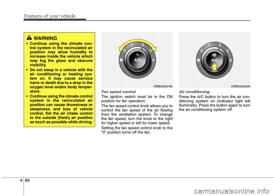
Fan speed control
The ignition switch must be in the ON
position for fan operation.
The fan speed control knob allows you to
control the fan speed of the air flowing
from the ventilation system. To change
the fan speed, turn the knob to the right
for higher speed or left for lower speed.
Setting the fan speed control knob to the
“0” position turns off the fan.
Air conditioning
Press the A/C button to turn the air con-
ditioning system on (indicator light will
illuminate). Press the button again to turn
the air conditioning system off.
ORB040073NORB040354N
WARNING
Continue using the climate con-
trol system in the recirculated air
position may allow humidity to
increase inside the vehicle which
may fog the glass and obscure
visibility.
Do not sleep in a vehicle with the air conditioning or heating sys-
tem on. It may cause serious
harm or death due to a drop in the
oxygen level and/or body temper-
ature.
Continue using the climate control system in the recirculated air
position can cause drowsiness or
sleepiness, and loss of vehicle
control. Set the air intake control
to the outside (fresh) air position
as much as possible while driving.
Page 146 of 370

Features of your vehicle
68
4
✽
✽
NOTICE
• When using the air conditioning sys-
tem, monitor the temperature gauge
closely while driving up hills or in
heavy traffic when outside tempera-
tures are high. Air conditioning sys-
tem operation may cause engine over-
heating. Continue to use the blower
fan but turn the air conditioning sys-
tem off if the temperature gauge indi-
cates engine overheating.
• When opening the windows in humid weather air conditioning may create
water droplets inside the vehicle.
Since excessive water droplets may
cause damage to electrical equipment,
air conditioning should only be used
with the windows closed.
Air conditioning system operation tips
If the vehicle has been parked in direct
sunlight during hot weather, open the
windows for a short time to let the hot
air inside the vehicle escape.
To help reduce moisture inside of the windows on rainy or humid days,
decrease the humidity inside the vehi-
cle by operating the air conditioning
system.
During air conditioning system opera- tion, you may occasionally notice a
slight change in engine speed as the
air conditioning compressor cycles.
This is a normal system operation
characteristic.
Use the air conditioning system every month only for a few minutes to ensure
maximum system performance. When using the air conditioning sys-
tem, you may notice clear water drip-
ping (or even puddling) on the ground
under the passenger side of the vehi-
cle. This is a normal system operation
characteristic.
Operating the air conditioning system in the recirculated air position provides
maximum cooling, however, continual
operation in this mode may cause the
air inside the vehicle to become stale.
During cooling operation, you may occasionally notice a misty air flow
because of rapid cooling and humid air
intake. This is a normal system opera-
tion characteristic.
If you operate air conditioner exces- sively, the difference between the tem-
perature of the outside air and that of
the windshield could cause the outer
surface of the windshield to fog up,
causing loss of visibility. In this case,
set the mode selection knob or button
to the position and fan speed con-
trol to the lower speed.
Page 153 of 370

475
Features of your vehicle
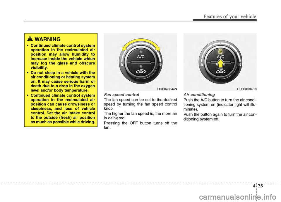
Fan speed control
The fan speed can be set to the desired
speed by turning the fan speed control
knob.
The higher the fan speed is, the more air
is delivered.
Pressing the OFF button turns off the
fan.
Air conditioning
Push the A/C button to turn the air condi-
tioning system on (indicator light will illu-
minate).
Push the button again to turn the air con-
ditioning system off.
ORB040344NORB040346N
WARNING
Continued climate control systemoperation in the recirculated air
position may allow humidity to
increase inside the vehicle which
may fog the glass and obscure
visibility.
Do not sleep in a vehicle with the air conditioning or heating system
on. It may cause serious harm or
death due to a drop in the oxygen
level and/or body temperature.
Continued climate control system operation in the recirculated air
position can cause drowsiness or
sleepiness, and loss of vehicle
control. Set the air intake control
to the outside (fresh) air position
as much as possible while driving.
Page 330 of 370

755
Maintenance
Instrument panel (Driver’s side fuse panel)
Description Fuse ratingProtected component
P/OUTLET 15A Cigarette Lighter & Power Outlet (Power Outlet)
C/LIGHTER 15A Cigarette Lighter & Power Outlet (Cigarette Lighter)
ACC 10A Audio, Power Outside Mirror Switch
A/BAG IND 10A Instrument Cluster (Air Bag IND.)
A/BAG 10A SRS Control Module, Telltale, Passenger Occupant Detection Sensor
T/SIG 10A Hazard Switch
IG1 2 10A Not Used
WIPER RR 15A Multifunction Switch (Wiper), Rear Wiper Moter
SPARE 6 15A Not Used
SPARE 1 10A Not Used
FOG LP FRT 10A Front Fog Lamp Relay
ROOM LP 2 10A Auto Cut Relay
STOP LP 15AStop Lamp Switch, Battery Sensor, Stop Lamp RelayE/R Fuse & Relay Box (HAC Relay),
Data Link Connector
CLUSTER 10A Instrument Cluster (MICOM, IND.), BCM
IG1 1 10AStop Lamp Switch, ECO Switch, Driver/Passenger Seat Heater Module
Tire Pressure Monitoring Module, ATM Shift Lever Switch ILL. EPS Control Module, Rheostat
ABS 10AABS Control Module, ESC Control Module,
ESC Off Switch E/R Fuse & Relay Box (Multipurpose Check Connector, HAC Relay)
B/UP LP 10A Back-Up Lamp Switch
ECU 10A ECM, PCM
H/LP LH 10A Head Lamp LH
HAZARD 15A Hazard Relay, Hazard Switch
SPARE 2 25A Not Used
SUNROOF 15A Sunroof Motor
Page 334 of 370

759
Maintenance
Headlight, position light, turn sig-
nal light, side marker light and
front fog light bulb replacement
(1) Headlight (High/Low)
(2) Front turn signal light / Position light
(3) Side marker
(4) Front fog light (if equipped)
Headlight / Side marker
1. Open the hood.
2. Remove the headlight bulb cover byturning it counterclockwise.
3. Disconnect the headlight bulb socket- connector.
4. Unsnap the headlight bulb retaining wire by depressing the end and push-
ing it upward.
5. Remove the bulb from the headlight assembly.
6. Install a new headlight bulb and snap the headlight bulb retaining wire into
position by aligning the wire with the
groove on the bulb.
7. Connect the headlight bulb socket- connector.
8. Install the headlight bulb cover by turn- ing it clockwise.
✽ ✽NOTICE
If the headlight aiming adjustment is
necessary after the headlight assembly is
reinstalled, consult an authorized
HYUNDAI dealer.
ORB070025ORB071048N