2012 Hyundai Accent instrument cluster
[x] Cancel search: instrument clusterPage 209 of 370

511
Driving your vehicle
For smooth operation, depress the brakepedal when shifting from N (Neutral) to aforward or reverse gear. Transaxle ranges
The indicator in the instrument cluster
displays the shift lever position when the
ignition switch is in the ON position.
P (Park)
Always come to a complete stop before
shifting into P (Park). This position locks
the transaxle and prevents the drive
wheels from rotating.
WARNING- Automatic
transaxle
Always check the surrounding
areas near your vehicle for peo-
ple, especially children, before
shifting a car into D (Drive) or R
(Reverse).
Before leaving the driver’s seat, always make sure the shift lever
is in the P (Park) position; then
set the parking brake fully and
shut the engine off. Unexpected
and sudden vehicle movement
can occur if these precautions
are not followed in the order iden-
tified.
CAUTION
To avoid damage to your transaxle, do not accelerate theengine in R (Reverse) or any for-ward gear position with thebrakes on.
When stopped on an incline, do not hold the vehicle stationarywith engine power. Use the serv-ice brake or the parking brake.
Do not shift from N (Neutral) or P (Park) into D (Drive), or R(Reverse) when the engine isabove idle speed.
WARNING
Shifting into P (Park) while the vehicle is in motion will cause the
drive wheels to lock which will
cause you to lose control of the
vehicle.
Do not use the P (Park) position in place of the parking brake.
Always make sure the shift lever
is latched in the P (Park) position
and set the parking brake fully.
Never leave a child unattended in a vehicle.
Page 223 of 370

525
Driving your vehicle
Vehicle stability management
(VSM) (if equipped)
This system provides further enhance-
ments to vehicle stability and steering
responses when a vehicle is driving on a
slippery road or for vehicle detected
changes in coefficient of friction between
right wheels and left wheels when braking.
VSM operation
When the VSM is in operation, ESC indi-
cator light ( ) blinks.
When the vehicle stability management
is operating properly, you can feel a slight
pulsation in the vehicle and/or abnormal
steering responses (EPS). This is only
the effect of brake and EPS control and
is a normal operating condition.
The VSM does not operate when:
Driving on banked roads with gradientsor inclines.
Driving rearward
ESC OFF indicator light ( ) remains on the instrument cluster
EPS indicator light remains on the instrument cluster
VSM operation off
If you press the ESC OFF button to turn off
the ESC, the VSM will also cancel and the
ESC OFF indicator light ( ) illuminates.
To turn on the VSM, press the button again.
The ESC OFF indicator light goes out.
Malfunction indicator
The VSM can be deactivated even if you
don’t cancel the VSM operation by press-
ing the ESC OFF button. It indicates that
a malfunction has been detected some-
where in the Electric Power Steering sys-
tem or VSM system. If the ESC indicator
light ( ) or EPS warning light remains
on, take your vehicle to an authorized
HYUNDAI dealer and have the system
checked.
WARNING
The Vehicle Stability Managementsystem is not a substitute for
safe driving practices but a sup-
plementary function only. It is the
responsibility of the driver to
always check the speed and the
distance to the vehicle ahead.
Always hold the steering wheel
firmly while driving.
Your vehicle is designed to acti- vate according to the driver’s
intention, even with installed
VSM. Always follow all the normal
precautions for driving at safe
speeds for the conditions –
including driving inclement
weather and on a slippery road.
Driving with varying tire or wheel sizes may cause the VSM system
to malfunction. When replacing
tires, make sure they are the
same size as your original tires.
Page 225 of 370

527
Driving your vehicle
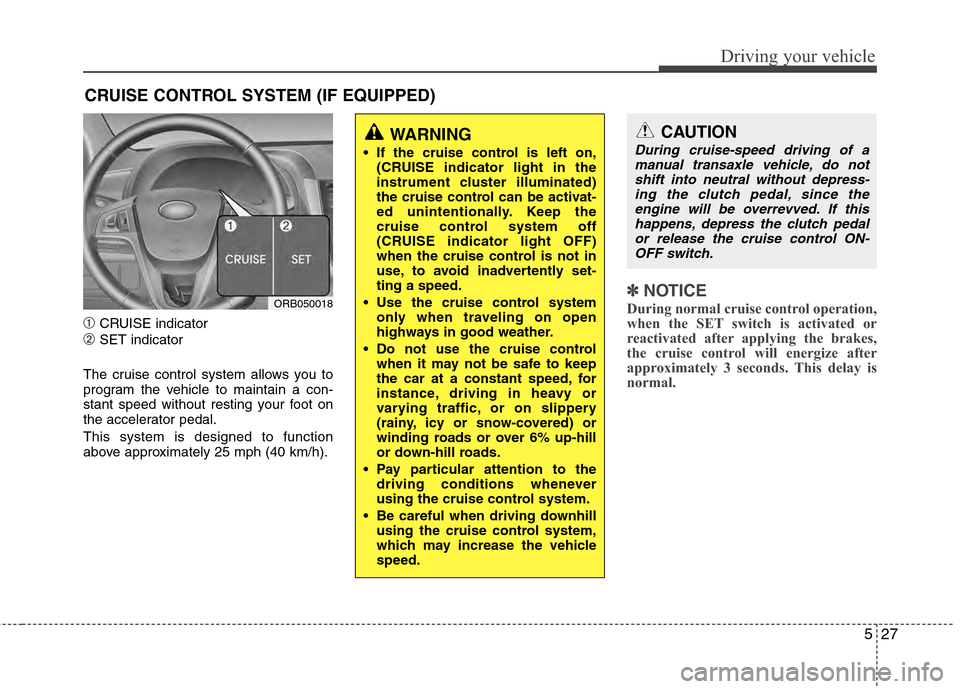
➀CRUISE indicator
➁SET indicator
The cruise control system allows you to
program the vehicle to maintain a con-
stant speed without resting your foot on
the accelerator pedal.
This system is designed to function
above approximately 25 mph (40 km/h).
✽ ✽ NOTICE
During normal cruise control operation,
when the SET switch is activated or
reactivated after applying the brakes,
the cruise control will energize after
approximately 3 seconds. This delay is
normal.
CRUISE CONTROL SYSTEM (IF EQUIPPED)
WARNING
If the cruise control is left on,
(CRUISE indicator light in the
instrument cluster illuminated)
the cruise control can be activat-
ed unintentionally. Keep the
cruise control system off
(CRUISE indicator light OFF)
when the cruise control is not in
use, to avoid inadvertently set-
ting a speed.
Use the cruise control system only when traveling on open
highways in good weather.
Do not use the cruise control when it may not be safe to keep
the car at a constant speed, for
instance, driving in heavy or
varying traffic, or on slippery
(rainy, icy or snow-covered) or
winding roads or over 6% up-hill
or down-hill roads.
Pay particular attention to the driving conditions whenever
using the cruise control system.
Be careful when driving downhill using the cruise control system,
which may increase the vehicle
speed.
ORB050018
CAUTION
During cruise-speed driving of amanual transaxle vehicle, do notshift into neutral without depress-ing the clutch pedal, since theengine will be overrevved. If thishappens, depress the clutch pedalor release the cruise control ON-OFF switch.
Page 226 of 370

Driving your vehicle
28
5
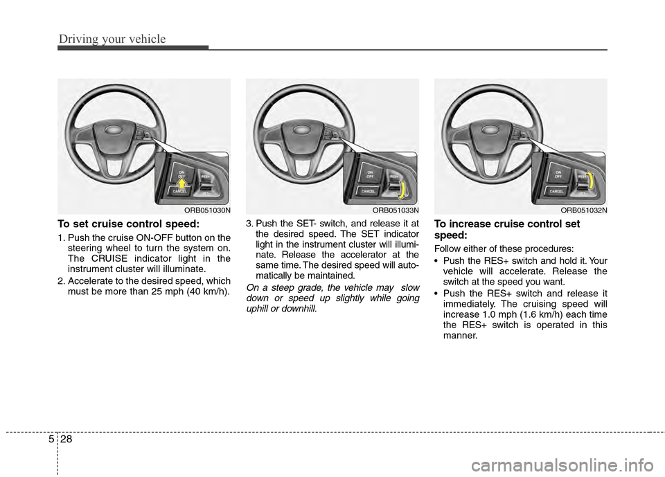
To set cruise control speed:
1. Push the cruise ON-OFF button on the
steering wheel to turn the system on.
The CRUISE indicator light in the
instrument cluster will illuminate.
2. Accelerate to the desired speed, which must be more than 25 mph (40 km/h). 3. Push the SET- switch, and release it at
the desired speed. The SET indicator
light in the instrument cluster will illumi-
nate. Release the accelerator at the
same time. The desired speed will auto-
matically be maintained.
On a steep grade, the vehicle may slowdown or speed up slightly while goinguphill or downhill.
To increase cruise control set
speed:
Follow either of these procedures:
Push the RES+ switch and hold it. Your vehicle will accelerate. Release the
switch at the speed you want.
Push the RES+ s witch and release it
immediately. The cruising speed will
increase 1.0 mph (1.6 km/h) each time
the RES+ s witch is operated in this
manner.
ORB051033NORB051032NORB051030N
Page 228 of 370

Driving your vehicle
30
5
Each of these actions will cancel cruise
control operation (the SET indicator lightin the instrument cluster will go off), but itwill not turn the system off. If you wish toresume cruise control operation, pushthe RES+ switch located on your steeringwheel. You will return to your previously preset speed.
To resume cruising speed at
more than approximately 25 mph
(40 km/h):
If any method other than the cruise
ON/OFF switch was used to cancel cruis-
ing speed and the system is still activat-
ed, the most recent set speed will auto-
matically resume when the RES+ switch
is pushed.
It will not resume, however, if the vehicle
speed has dropped below approximately
25 mph (40 km/h).
✽ ✽ NOTICE
Always check the road conditions when
pressing the RES+ switch to resume the
speed.
To turn cruise control off, do one
of the following:
Push the cruise ON/OFF button (the
CRUISE indicator light in the instru-
ment cluster will go off).
Turn the ignition off.
Both of these actions cancel cruise con- trol operation. If you want to resume cruise control operation, repeat the stepsprovided in “To set cruise control speed” on the previous page.
ORB051032NORB051033N
Page 330 of 370

755
Maintenance
Instrument panel (Driver’s side fuse panel)
Description Fuse ratingProtected component
P/OUTLET 15A Cigarette Lighter & Power Outlet (Power Outlet)
C/LIGHTER 15A Cigarette Lighter & Power Outlet (Cigarette Lighter)
ACC 10A Audio, Power Outside Mirror Switch
A/BAG IND 10A Instrument Cluster (Air Bag IND.)
A/BAG 10A SRS Control Module, Telltale, Passenger Occupant Detection Sensor
T/SIG 10A Hazard Switch
IG1 2 10A Not Used
WIPER RR 15A Multifunction Switch (Wiper), Rear Wiper Moter
SPARE 6 15A Not Used
SPARE 1 10A Not Used
FOG LP FRT 10A Front Fog Lamp Relay
ROOM LP 2 10A Auto Cut Relay
STOP LP 15AStop Lamp Switch, Battery Sensor, Stop Lamp RelayE/R Fuse & Relay Box (HAC Relay),
Data Link Connector
CLUSTER 10A Instrument Cluster (MICOM, IND.), BCM
IG1 1 10AStop Lamp Switch, ECO Switch, Driver/Passenger Seat Heater Module
Tire Pressure Monitoring Module, ATM Shift Lever Switch ILL. EPS Control Module, Rheostat
ABS 10AABS Control Module, ESC Control Module,
ESC Off Switch E/R Fuse & Relay Box (Multipurpose Check Connector, HAC Relay)
B/UP LP 10A Back-Up Lamp Switch
ECU 10A ECM, PCM
H/LP LH 10A Head Lamp LH
HAZARD 15A Hazard Relay, Hazard Switch
SPARE 2 25A Not Used
SUNROOF 15A Sunroof Motor
Page 331 of 370

Maintenance
56
7
Description Fuse rating Protected component
SPARE 3 10A Not Used
TCU 15A Vehicle Speed Sensor, Transaxle Range Switch
IGN COIL 15A Ignition Coil #1~#4, Condenser
IG2 10APower Window Relay, A/C Control Module, Instrument Cluster (MICOM) BCM,
Sunroof Motor, E/R Fuse & Relay Box (Blower Relay)
WIPER FRT 25A Multifunction Switch (Wiper), Front Wiper Motor
DR LOCK 20A Door Lock/Unlock Relay, Two Turn Unlock Relay Driver Door Lock Actuator
SPARE 4 25A Not Used
S/HEATER 15A Driver/Passenger Seat Heater Module
SPARE 5 10A Not Used
ROOM LP 1 10AInstrument Cluster (IND.,ILL.), Tire Pressure Monitoring Module, BCM A/C Control Module,
Luggage Room Lamp, Trunk Room Lamp Center Room Lamp, Overhead Console Lamp, Map Lamp
AUDIO 20A Audio
TAIL LP LH 10ARear Combination Lamp LH, Head Lamp LH, Front Turn Signal Lamp LH
License Lamp LH/RH (4Door), License Lamp (5Door)
TAIL LP RH 10AHead Lamp RH, Rear Combination Lamp RH, Rheostat, Audio Front Turn Signal Lamp RH,
Hazard Switch, Instrument Cluster (ILL.+) AUX & USB Jack, ESC Off Switch, A/C Switch,
ECO Switch Multifunction Switch (Remote Control), A/C Control Module R\
ear Defogger Switch,
Front Deicer Switch, ATM Shift Lever Switch ILL.
START 10A Transaxle Range Switch, Ignition Lock Switch
H/LP RH 10A Instrument Cluster (High Beam IND.), Head Lamp RH
P/WDW LH 25A Power Window Main Switch, Rear Power Window Switch LH
P/WDW RH 25A Power Window Main Switch, Rear Power Window Switch RHPassenger Power Window Switch
HTD MIRR 10AECM, PCM, Rear Defogger Switch, Driver Power Outside Mirror
Passenger Power Outside Mirror
A/CON 10A A/C Control Module (Auto A/C)
BLOWER 10A ECM, PCM, Blower Switch, Blower Resistor A/C Control Module (Manual A/C)
Page 332 of 370

757
Maintenance
Engine compartment main fuse panel
DescriptionFuse rating Protected component
MULTI FUSE MDPS
80A EPS Control Module
BLOWER 40A Blower Relay
RR HTD 40A I/P Junction Box (Rear Defogger Relay)
ABS 2 40A ABS Control Module, ESC Control Module
ABS 1 40A ABS Control Module, ESC Control Module, Multipurpose Check Connector
ALT 125AAlternator, E/R Fuse & Relay Box
(Multi Fuse : ABS 1, ABS 2, MDPS, RR HTD, BLOWER, Fuse : A/CON)
B+1 50AI/P Junction Box (Power Connector Fuse : ROOM LP 1, AUDIO, Fuse : FOG LP FRT,
ROOM LP 2, STOP LP, Relay : Tail Lamp)
FUSE
IG250AStart Relay, Ignition Switch
IG140AIgnition Switch
ECU 1 30A Fuse : ECU 2, Engine Control Relay
C/FAN 30A Cooling Fan (High) Relay, Cooling Fan (Low) Relay
B+2 50A I/P Junction Box (Fuse : S/HEATER, SUNROOF, DR LOCK, HAZARD, Relay : Power Window)
HORN 10A Horn Relay
F/PUMP 10A Fuel Pump Relay
A/CON 10A A/CON Relay
INJECTOR 15A ECM, PCM, Oil Control Valve #1/#2, Oxygen Sensor (Up)/(Down), Fuel Pump Relay
SENSOR 10A ECM, PCM, Canister Purge Control Solenoid Valve, Variable Intake Solenoid Valve,
Canister Close Valve, Immobilizer Module, A/CON Relay
Cooling Fan (High) Relay, Cooling Fan (Low) Relay
ECU 2 10A ECM, PCM
B/UP LP 10A PCM, Transaxle Range Switch, Instrument Cluster,
Rear Combination Lamp LH/RH, ATM Shift Lever Switch ILL.
WIPER 10A ECM, PCM, Multifunction Switch (Wiper), Front Wiper Motor