Page 128 of 306

TRACTION CONTROL (IF EQUIPPED)
Your vehicle may be equipped with a traction control system which helps
you maintain stability and steerability, especially on slippery road
surfaces such as snow- or ice-covered roads and gravel roads, by
reducing engine power and/or selectively applying the rear brakes.
Note:The traction control system does not apply the brakes when
vehicle speed is above 25 mph (40 km/h).
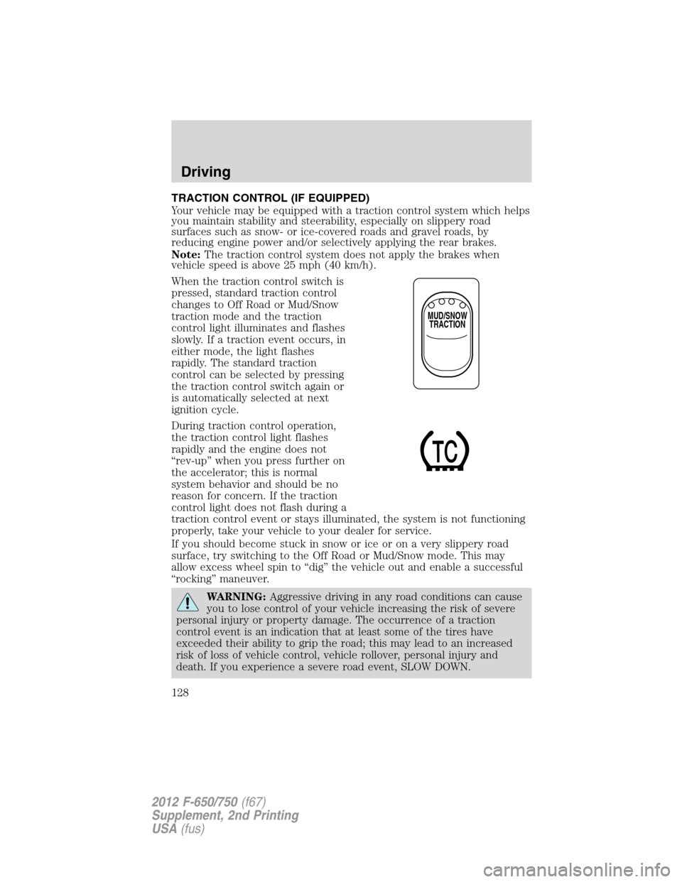
When the traction control switch is
pressed, standard traction control
changes to Off Road or Mud/Snow
traction mode and the traction
control light illuminates and flashes
slowly. If a traction event occurs, in
either mode, the light flashes
rapidly. The standard traction
control can be selected by pressing
the traction control switch again or
is automatically selected at next
ignition cycle.
During traction control operation,
the traction control light flashes
rapidly and the engine does not
“rev-up” when you press further on
the accelerator; this is normal
system behavior and should be no
reason for concern. If the traction
control light does not flash during a
traction control event or stays illuminated, the system is not functioning
properly, take your vehicle to your dealer for service.
If you should become stuck in snow or ice or on a very slippery road
surface, try switching to the Off Road or Mud/Snow mode. This may
allow excess wheel spin to “dig” the vehicle out and enable a successful
“rocking” maneuver.
WARNING:Aggressive driving in any road conditions can cause
you to lose control of your vehicle increasing the risk of severe
personal injury or property damage. The occurrence of a traction
control event is an indication that at least some of the tires have
exceeded their ability to grip the road; this may lead to an increased
risk of loss of vehicle control, vehicle rollover, personal injury and
death. If you experience a severe road event, SLOW DOWN.
MUD/SNOW
TRACTION
Driving
128
2012 F-650/750(f67)
Supplement, 2nd Printing
USA(fus)
Page 129 of 306

AIR SUSPENSION (IF EQUIPPED)
The air suspension system automatically adjusts to different loads to
maintain a constant frame height, allows for ease of vehicle loading and
provides improved vehicle ride and increased driver comfort.
Note:The vehicle must not be operated without air in the suspension
springs. Operating the vehicle without air in the air suspension springs
damages the suspension, degrades ride performance and may cause
property damage.
Air suspension dump switch (if equipped)
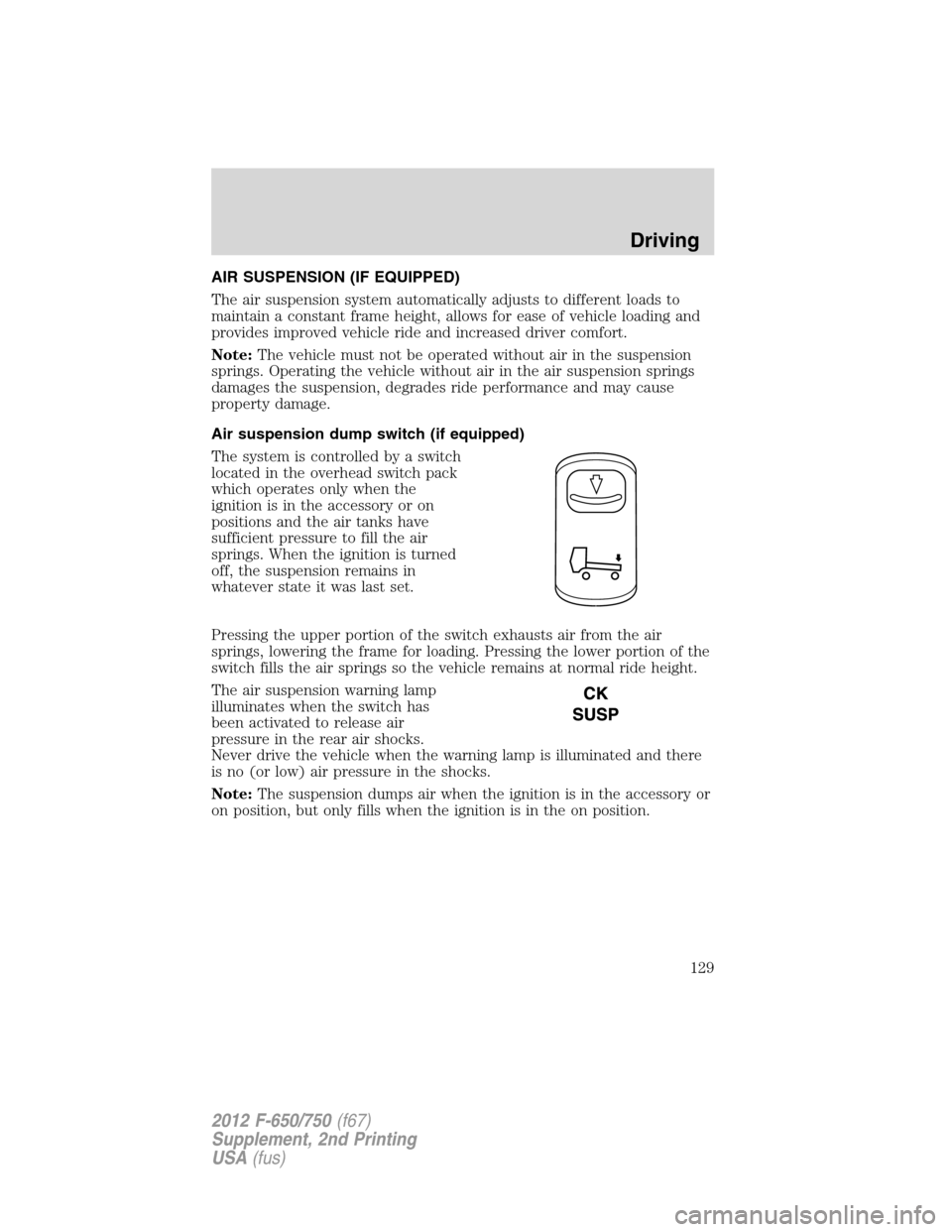
The system is controlled by a switch
located in the overhead switch pack
which operates only when the
ignition is in the accessory or on
positions and the air tanks have
sufficient pressure to fill the air
springs. When the ignition is turned
off, the suspension remains in
whatever state it was last set.
Pressing the upper portion of the switch exhausts air from the air
springs, lowering the frame for loading. Pressing the lower portion of the
switch fills the air springs so the vehicle remains at normal ride height.
The air suspension warning lamp
illuminates when the switch has
been activated to release air
pressure in the rear air shocks.
Never drive the vehicle when the warning lamp is illuminated and there
is no (or low) air pressure in the shocks.
Note:The suspension dumps air when the ignition is in the accessory or
on position, but only fills when the ignition is in the on position.
Driving
129
2012 F-650/750(f67)
Supplement, 2nd Printing
USA(fus)
Page 131 of 306

BRAKE-SHIFT INTERLOCK
Vehicles equipped with a gasoline engine have a brake-shift interlock
feature that prevents the gearshift lever from being moved from P (Park)
when the ignition is in the on position and the brake pedal is not pressed.
If you cannot move the gearshift lever out of P (Park) with the ignition
in the on position and the brake pedal pressed, it is possible that a fuse
has blown or the vehicle’s brake lamps are not operating properly. Refer
toFuses and relaysin theRoadside Emergencieschapter.
If the fuse is not blown and the brake lamps are working properly, the
following procedure will allow you to move the gearshift lever from P (Park):
1. Apply the parking brake, and turn
the engine off.
2. Remove the lower finish panel
below the steering column
3. Turn the key to on (position 4),
but do not start engine.
4. Pull back on the solenoid, and at
the same time, shift the
transmission into N (Neutral).
5. Start the vehicle.
See your authorized dealer as
soon as possible if this
procedure is used.
WARNING:Do not drive
your vehicle until you verify
that the brake lamps are working.
1
2
34
5
Driving
131
2012 F-650/750(f67)
Supplement, 2nd Printing
USA(fus)
Page 133 of 306

several transmission upshifts and downshifts; during this learning
process, slightly firmer shifts may occur. After this learning process,
normal shift feel and shift scheduling will resume.
P (Park)
This position locks the transmission and prevents the rear wheels from
turning.
To put your vehicle in gear:
1. Start the engine
2. Press the brake pedal
3. Move the gearshift lever into the desired gear
To put your vehicle in P (Park):
1. Come to a complete stop
2. Move the gearshift lever and securely latch it in P (Park)
WARNING:Always set the parking brake fully and make sure
the gearshift is latched in P (Park). Turn the ignition to the off
position and remove the key whenever you leave your vehicle.
R (Reverse)
With the gearshift lever in R (Reverse), the vehicle will move backward.
Always come to a complete stop before shifting into and out of R
(Reverse).
N (Neutral)
With the gearshift lever in N (Neutral), the vehicle can be started and is
free to roll. Hold the brake pedal down while in this position.
D (Drive)
This is the normal driving position for the best fuel economy. This
position allows automatic upshifts and downshifts through gears one
through six.
4 (Fourth)
This position allows automatic upshifts and downshifts in gears one
through four.
2 (Second)
Use 2 (Second) to start-up on slippery roads or to provide additional
engine braking on downgrades.
Driving
133
2012 F-650/750(f67)
Supplement, 2nd Printing
USA(fus)
Page 153 of 306
HAZARD FLASHER
The hazard flasher control is located
on the steering column, just behind
the steering wheel. The hazard
flashers operate when the ignition is
off.
Press the flasher control and all
front and rear direction signals will
flash. Press the flasher control again
to turn them off. Use it when your
vehicle is disabled and is creating a
safety hazard for other motorists.
Note:With extended use, the flasher may run down your battery.
FUSING
If electrical components in the vehicle are not working, a fuse may have
blown. Blown fuses are identified by a broken wire within the fuse.
Check the appropriate fuses before replacing any electrical components.
Note:Always replace a fuse with one that has the specified amperage
rating. Using a fuse with a higher amperage rating can cause severe wire
damage and could start a fire.
Roadside Emergencies
153
2012 F-650/750(f67)
Supplement, 2nd Printing
USA(fus)
Page 156 of 306
Power distribution box
WARNING:Always disconnect the battery before servicing high
current fuses.
WARNING:To reduce risk of electrical shock, always replace
the cover to the Power Distribution Box before reconnecting the
battery or refilling fluid reservoirs.
Fuse/Relay
locationFuse amp
ratingFuse description
1 20A Upfitter switches (AUX 2 and AUX 4)/Trailer
12V socket pin
2 30A Power seat (driver)
3 30A Power seat (passenger)
4 15A Windshield washer relay, Washer pump motor
5 5A Brake warning switch (hydraulic brake only)
6 20A Upfitter switches (AUX 1 and AUX 3)
7 15A Brake pressure switches, ABS event relay
8 20A DEF (Urea), Line heaters (diesel engine
only)
9 20A Ignition switch, Starter cutoff
503
502
501304
303
302 301
2119 22 2024
23401
207 201202 203204
209 206
208 205602
601118114
110106
102
117 113 109105
101
116 112 108104
115 111 107103
18 16
14 12 10 864
2
17 15
13 11 9 753
1
Roadside Emergencies
156
2012 F-650/750(f67)
Supplement, 2nd Printing
USA(fus)
Page 157 of 306

Fuse/Relay
locationFuse amp
ratingFuse description
10 15A Air tank moisture removal valve
11 30A Electric trailer brake
12 20A Passenger compartment fuse box 5 and 21
13 15A Instrument cluster/Gateway module
14 20A Nitrogen oxide sensor (diesel engine only)
15 — Not used
16 5A Bendix�Air ABS
17 — Not used
18 10A Fuel transfer pump
19 15A Powertrain control module power 1 (gasoline
engine only)
20 10A Powertrain control module power 2 (gasoline
engine only)
21 20A Powertrain control module power 3 (gasoline
engine only)
22 20A Powertrain control module power 4 (gasoline
engine only)
23 — Not used
24 10A Powertrain control module keep-alive power
(gasoline engine only)
101 30A Bendix Air ABS relay (Air brake vehicles
only)
Hydraulic brakes module (Hydraulic brake
vehicles only)
102 20A Ignition switch
103 20A Ignition switch, Passenger compartment fuse
box fuses 19, 29 and 30
104 20A Power point
105 20A Power door lock switches
106 30A Main light switch, Multi-function switch
107 50A Passenger compartment fuse box fuses 1, 2,
3, 4, 12, 13, 14 and 15
Roadside Emergencies
157
2012 F-650/750(f67)
Supplement, 2nd Printing
USA(fus)
Page 158 of 306

Fuse/Relay
locationFuse amp
ratingFuse description
108 40A Fuel heater (diesel engine only)
20A Fuel pump module (gasoline engine only)
109 40A Power window
110 30A Windshield wiper
111 30A Body builder relay, Parking lamps
112 40A Blower motor
113 30A Heated seats, Air-Ride seat
114 20A Aftertreatment DCU
115 20A Ignition switch, Passenger compartment fuse
box fuses 8, 9, 10 and 11
116 30A Left/Right turn relays, Back-up lamp relay
117 20A Stoplamps
118 60A Hydraulic brake vehicles (Trailer tow package
only)
601 60A Trailer socket
602 60A Air brake trailer tow fuse block
30A Hydraulic brakes pump motor 2
201 — Windshield washer relay
202 — Wiper high/low relay
203 — Wiper run/park relay
204 — Windshield wiper relay
205 — Body builder relay, right turn
206 — Body builder relay, left turn
207 — ABS event relay (Hydraulic brake vehicles
only)
208 — Body builder relay, back-up lamps relay
209 — Auxiliary stoplamp relay
301 — Fuel heater/Fuel transfer pump relay (diesel
engine only)
— Fuel pump module (gasoline engine only)
302 — Body builder relay, parking lamps relay
303 — Blower motor relay
Roadside Emergencies
158
2012 F-650/750(f67)
Supplement, 2nd Printing
USA(fus)