Page 340 of 448

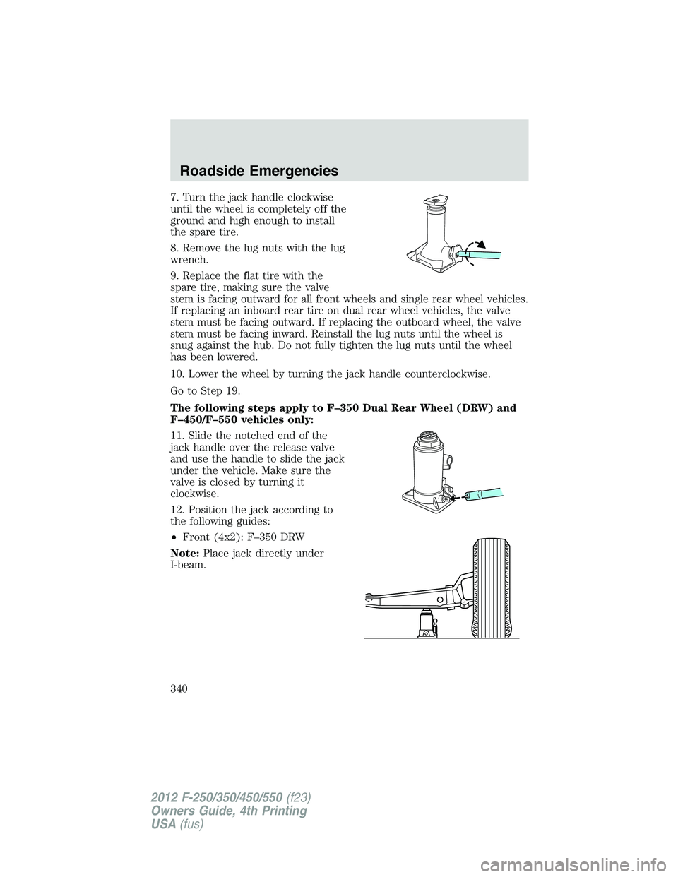
7. Turn the jack handle clockwise
until the wheel is completely off the
ground and high enough to install
the spare tire.
8. Remove the lug nuts with the lug
wrench.
9. Replace the flat tire with the
spare tire, making sure the valve
stem is facing outward for all front wheels and single rear wheel vehicles.
If replacing an inboard rear tire on dual rear wheel vehicles, the valve
stem must be facing outward. If replacing the outboard wheel, the valve
stem must be facing inward. Reinstall the lug nuts until the wheel is
snug against the hub. Do not fully tighten the lug nuts until the wheel
has been lowered.
10. Lower the wheel by turning the jack handle counterclockwise.
Go to Step 19.
The following steps apply to F–350 Dual Rear Wheel (DRW) and
F–450/F–550 vehicles only:
11. Slide the notched end of the
jack handle over the release valve
and use the handle to slide the jack
under the vehicle. Make sure the
valve is closed by turning it
clockwise.
12. Position the jack according to
the following guides:
• Front (4x2): F–350 DRW
Note: Place jack directly under
I-beam.Roadside Emergencies
340
2012 F-250/350/450/550 (f23)
Owners Guide, 4th Printing
USA (fus)
Page 342 of 448
• Rear: F-450/F-550
13. Insert the jack handle into the
pump linkage.
14. Use an up-and-down motion
with the jack handle to raise the
wheel completely off the ground.
Hydraulic jacks are equipped
with a pressure release valve
that prevents lifting loads which
exceed the jack’s rated capacity.
15. Remove the lug nuts with the lug wrench.
16. Replace the flat tire with the spare tire, making sure the valve stem
is facing outward on all front an inboard rear wheels. If replacing the
outboard wheel, the valve stem must be facing inward. Reinstall the lug
nuts until the wheel is snug against the hub. Do not fully tighten the lug
nuts until the wheel has been lowered.
17. Lower the wheel by slowly turning the release valve
counterclockwise. Opening the release valve slowly will provide a more
controlled rate of descent.Roadside Emergencies
342
2012 F-250/350/450/550 (f23)
Owners Guide, 4th Printing
USA (fus)
Page 343 of 448
The following steps apply to all vehicles:
18. Remove the jack and fully
tighten the lug nuts in the order
shown. Refer to Wheel lug nut
torque specifications later in this
chapter for the proper lug nut
torque specification.
8–lug nut torque sequence
10–lug nut torque sequence
19. Stow the flat tire. Refer to Stowing the flat/spare tire if the vehicle
is equipped with a spare tire carrier.
20. Stow the jack, jack handle and lug wrench. Make sure the jack is
securely fastened so it does not rattle when driving.
21. Unblock the wheels. Roadside Emergencies
343
2012 F-250/350/450/550 (f23)
Owners Guide, 4th Printing
USA (fus)
Page 346 of 448

Stowing the flat/spare tire
Note: Failure to follow spare tire stowage instructions may result in
failure of cable or loss of spare tire.
If you are stowing a tire that requires reattaching it to the
vehicle with a tether, perform these steps first, then proceed with
the steps following.
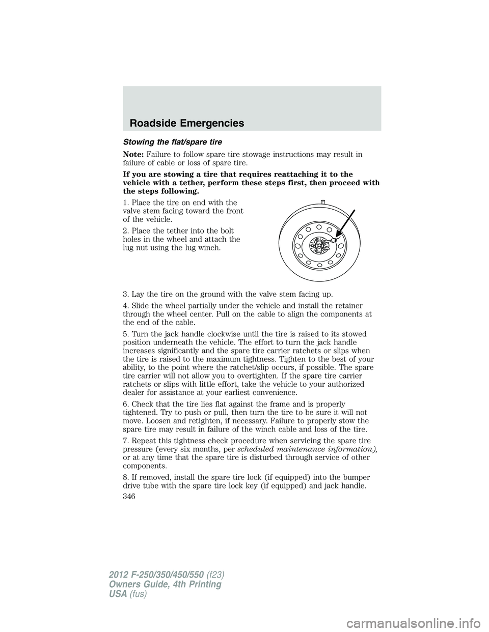
1. Place the tire on end with the
valve stem facing toward the front
of the vehicle.
2. Place the tether into the bolt
holes in the wheel and attach the
lug nut using the lug winch.
3. Lay the tire on the ground with the valve stem facing up.
4. Slide the wheel partially under the vehicle and install the retainer
through the wheel center. Pull on the cable to align the components at
the end of the cable.
5. Turn the jack handle clockwise until the tire is raised to its stowed
position underneath the vehicle. The effort to turn the jack handle
increases significantly and the spare tire carrier ratchets or slips when
the tire is raised to the maximum tightness. Tighten to the best of your
ability, to the point where the ratchet/slip occurs, if possible. The spare
tire carrier will not allow you to overtighten. If the spare tire carrier
ratchets or slips with little effort, take the vehicle to your authorized
dealer for assistance at your earliest convenience.
6. Check that the tire lies flat against the frame and is properly
tightened. Try to push or pull, then turn the tire to be sure it will not
move. Loosen and retighten, if necessary. Failure to properly stow the
spare tire may result in failure of the winch cable and loss of the tire.
7. Repeat this tightness check procedure when servicing the spare tire
pressure (every six months, per scheduled maintenance information),
or at any time that the spare tire is disturbed through service of other
components.
8. If removed, install the spare tire lock (if equipped) into the bumper
drive tube with the spare tire lock key (if equipped) and jack handle.Roadside Emergencies
346
2012 F-250/350/450/550 (f23)
Owners Guide, 4th Printing
USA (fus)
Page 447 of 448

SecuriLock passive anti-theft
system ................................149–150
Servicing your vehicle ..............370
Setting the clock ...................61, 63
Snowplowing .................7, 316–317
SOS Post Crash Alert ...............189
Spark plugs,
specifications .....................410, 415
Special notice ................................8
ambulance conversions ..............8
diesel-powered vehicles .............7
four-wheel drive vehicles .......318
utility-type vehicles ....................7
Speed control ............................110
Starting a flex fuel vehicle .......268
Starting your vehicle ........265–268
jump starting ..........................348
Steering wheel
controls ....................................112
tilting .........................................99
SYNC � ..........................................77
T
Tailgate ......................................123
Tilt steering wheel ......................99
Tire Pressure Monitoring
System (TPMS)
Tires, Wheels and Loading ....237
Tires ...........................219–220, 331
alignment ................................229
care ..........................................225
changing ..................331, 334, 337
checking the pressure ............224
inflating ...................................221
label .........................................236
replacing ..................................227 rotating ....................................230
safety practices .......................229
sidewall information ...............232
snow tires and chains ............243
spare tire .................................332
terminology .............................220
tire grades ...............................220
treadwear ........................219, 226
Towing .......................................252
recreational towing .................263
Trailer Brake
Controller-Integrated ..............256
trailer towing ..........................252
wrecker ....................................351
Traction control ........................274
Trailer Brake
Controller-Integrated ................256
Trailer sway control ..................281
Transfer case
fluid checking .........................404
Transmission .............................287
brake-shift interlock (BSI) ....285
fluid, checking and adding
(automatic) .............................400
fluid, refill capacities ..............411
Turn signal ..................................91
U
Universal garage door opener ..116
Upfitter controls .......................114
USB port ......................................71
V
Vehicle Identification Number
(VIN) ..........................................417
Vehicle loading ..........................244
Ventilating your vehicle ...........269 Index
447
2012 F-250/350/450/550 (f23)
Owners Guide, 4th Printing
USA (fus)