Page 297 of 462

5. With the ignition in the on
position, pull back on the BSI
solenoid found on top of the
uncovered steering column and at
the same time, apply the brake
pedal and shift the transmission into
N (Neutral).
6. Reinstall the steering column cover, start the vehicle and release the
parking brake.
Note:After the transmission is shifted to N (Neutral), it is easier to
reinstall the cover when the column is in the middle or lower tilt
position.
WARNING:Do not drive your vehicle until you verify that the
brakelamps are working.
WARNING:When doing this procedure, you will be taking the
vehicle out of park which means the vehicle can roll freely. To
avoid unwanted vehicle movement, always fully set the parking brake
prior to doing this procedure. Use wheel chocks if appropriate.
WARNING:If the parking brake is fully released, but the brake
warning lamp remains illuminated, the brakes may not be
working properly. See your authorized dealer.
Brake-shift interlock – floor-shift transmission
This vehicle is equipped with a brake-shift interlock feature that prevents
the gearshift lever from being moved from P (Park) when the ignition is
in the on position unless the brake pedal is pressed.
If you cannot move the gearshift lever out of P (Park) with ignition in
the on position and the brake pedal pressed, it is possible that a fuse has
blown or the vehicle’s brake lamps are not operating properly. Refer to
Fuses and relaysin theRoadside Emergencieschapter.
Driving
297
2012 F-150(f12)
Owners Guide, 1st Printing
USA(fus)
Page 298 of 462
:
1. Apply the parking brake, turn the
ignition key t")
If the fuse is not blown and the brake lamps are working properly, the
following procedure will allow you to move the gearshift lever from P (Park):
1. Apply the parking brake, turn the
ignition key to the off position, and
remove the key.
2. Starting at the rear of the trim
panel, using a screwdriver (or
similar tool) carefully pry up the
trim panel from rear attachments
and disconnect it from the console
to expose the inside of the gearshift.
3. Locate the brake shift interlock
lever on the passenger side of the
shifter assembly.
4. Apply the brake pedal. Using a
screwdriver (or similar tool), press
and hold the brake shift interlock
lever while pulling the gearshift
lever out of the P (Park) position
and into the N (Neutral) position.
5. Install the trim panel.
6. Apply brake pedal, start the vehicle, and release the parking brake.
See your authorized dealer as soon as possible if this procedure
is used.
WARNING:Do not drive your vehicle until you verify that the
brakelamps are working.
WARNING:When doing this procedure, you will be taking the
vehicle out of park which means the vehicle can roll freely. To
avoid unwanted vehicle movement, always fully set the parking brake
prior to doing this procedure. Use wheel chocks if appropriate.
WARNING:If the parking brake is fully released, but the brake
warning lamp remains illuminated, the brakes may not be
working properly. See your authorized dealer.
Driving
298
2012 F-150(f12)
Owners Guide, 1st Printing
USA(fus)
Page 328 of 462

FUEL PUMP SHUT-OFF
In the event of a moderate to severe collision, this vehicle is equipped
with a fuel pump shut-off feature that stops the flow of fuel to the
engine. Not every impact will cause a shut-off.
Should your vehicle shut off after a collision due to this feature, you may
restart your vehicle by doing the following:
1. Turn the ignition switch to the off position.
2. Turn the ignition switch to the on position.
In some instances the vehicle may not restart the first time you try to
restart and may take one additional attempt.
WARNING:Failure to inspect and if necessary repair fuel leaks
after a collision may increase the risk of fire and serious injury.
Ford Motor Company recommends that the fuel system be inspected
by an authorized dealer after any collision.
FUSES AND RELAYS
Fuses
If electrical components in the
vehicle are not working, a fuse may
have blown. Blown fuses are
identified by a broken wire within
the fuse. Check the appropriate
fuses before replacing any electrical
components.
Note:Always replace a fuse with one that has the specified amperage
rating. Using a fuse with a higher amperage rating can cause severe wire
damage and could start a fire.
Standard fuse amperage rating and color
COLOR
Fuse
ratingMini
fusesStandard
fusesMaxi
fusesCartridge
maxi
fusesFuse link
cartridge
2A Grey Grey — — —
3A Violet Violet — — —
4A Pink Pink — — —
15
Roadside Emergencies
328
2012 F-150(f12)
Owners Guide, 1st Printing
USA(fus)
Page 329 of 462

COLOR
Fuse
ratingMini
fusesStandard
fusesMaxi
fusesCartridge
maxi
fusesFuse link
cartridge
5A Tan Tan — — —
7.5A Brown Brown — — —
10A Red Red — — —
15A Blue Blue — — —
20A Yellow Yellow Yellow Blue Blue
25A Natural Natural — Natural Natural
30A Green Green Green Pink Pink
40A — — Orange Green Green
50A — — Red Red Red
60A — — Blue Yellow Yellow
70A — — Tan — Brown
80A — — Natural Black Black
Passenger compartment fuse panel
The fuse panel is located under the right-hand side of the instrument
panel.
To remove the trim panel for access
to the fuse box, pull the panel
toward you and swing it out away
from the side and remove it. To
reinstall it, line up the tabs with the
grooves on the panel, then push it
shut.
To remove the fuse box cover, press in the tabs on both sides of the
cover, then pull the cover off.
To reinstall the fuse box cover, place the top part of the cover on the
fuse panel, then push the bottom part of the cover until you hear it click
shut. Gently pull on the cover to make sure it is seated properly.
Roadside Emergencies
329
2012 F-150(f12)
Owners Guide, 1st Printing
USA(fus)
Page 330 of 462
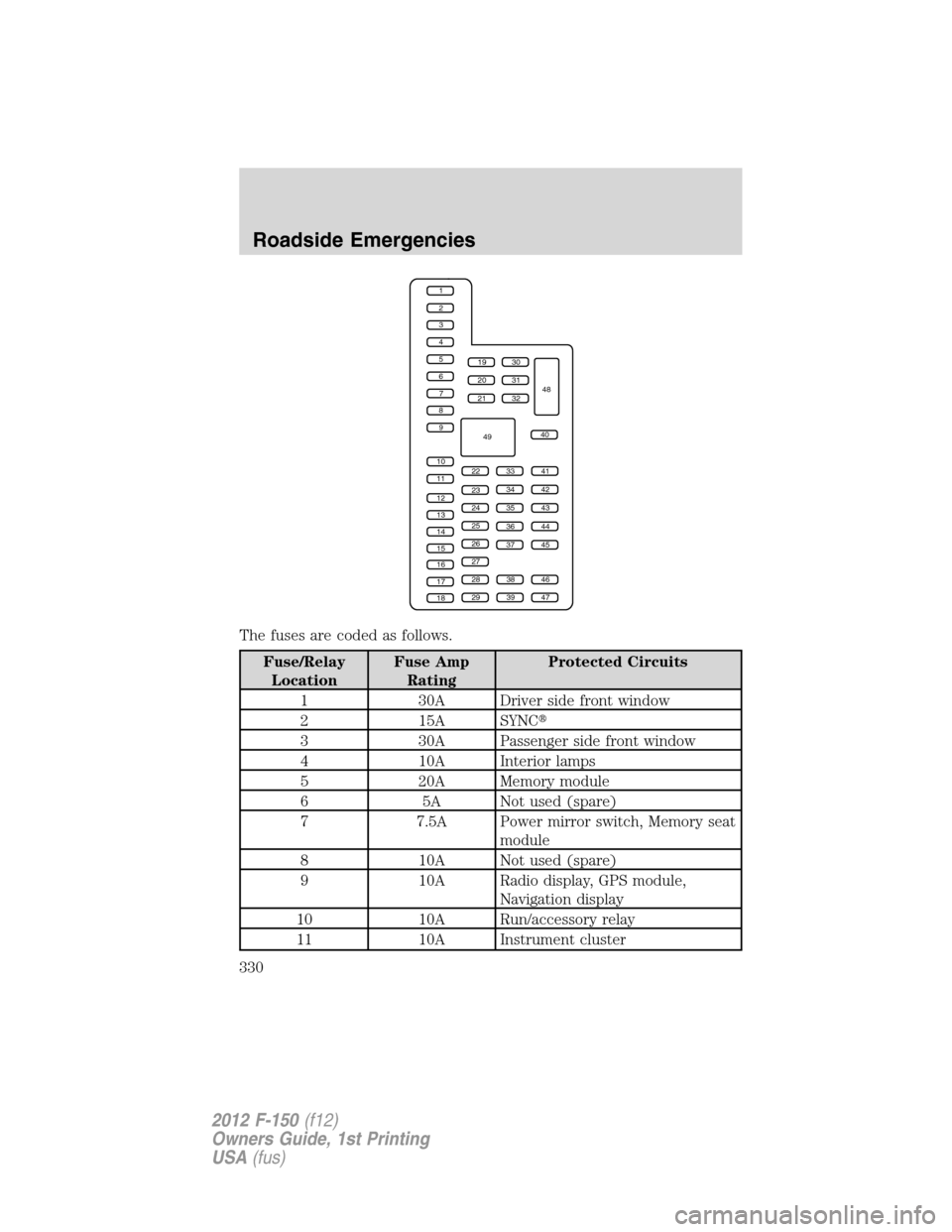
The fuses are coded as follows.
Fuse/Relay
LocationFuse Amp
RatingProtected Circuits
1 30A Driver side front window
2 15A SYNC�
3 30A Passenger side front window
4 10A Interior lamps
5 20A Memory module
6 5A Not used (spare)
7 7.5A Power mirror switch, Memory seat
module
8 10A Not used (spare)
9 10A Radio display, GPS module,
Navigation display
10 10A Run/accessory relay
11 10A Instrument cluster
1
2
3
4
5
6
7
8
9
10
11
12
13
14
15
16
17
18
19
20
21
223341
42
43
44
45
34
35
36
37
23
24
25
26
27
283846
394729
32
40
31
30
48
49
Roadside Emergencies
330
2012 F-150(f12)
Owners Guide, 1st Printing
USA(fus)
Page 331 of 462

Fuse/Relay
LocationFuse Amp
RatingProtected Circuits
12 15A Interior lighting, Puddle lamps,
Backlighting, Cargo lamp
13 15A Right turn signals/stop lamps
14 15A Left turn signals/stop lamps
15 15A Reverse lights, High-mounted stop
lamp
16 10A Right low-beam headlamp
17 10A Left low-beam headlamp
18 10A Brake-shift interlock, Keypad
illumination, PCM wakeup, PATS
19 20A Audio amplifier
20 20A Power door locks
21 10A Ambient lighting
22 20A Horn
23 15A Steering wheel control module
24 15A Datalink connector, Steering
wheel control module
25 15A Not used (spare)
26 5A Radio frequency module
27 20A Not used (spare)
28 15A Ignition switch
29 20A Radio/Navigation
30 15A Front parking lamps
31 5A BOO – IP, BOO – Engine
32 15A Delay/accessory – moon roof,
power windows, locks, Automatic
dimming mirror/Compass
33 10A Heated seats
34 10A Reverse sensing system, 4x4
switch, Rear video, Off road
indicator (SVT Raptor)
35 5A Hill descent switch (SVT Raptor)
Roadside Emergencies
331
2012 F-150(f12)
Owners Guide, 1st Printing
USA(fus)
Page 332 of 462

Fuse/Relay
LocationFuse Amp
RatingProtected Circuits
36 10A Restraint control module,
Occupant classification system
module
37 10A Trailer brake control
38 10A Delayed accessory – 110V power
point, Radio (AM/FM)
39 15A High beam headlamps
40 10A Rear park lamps
41 7.5A Passenger airbag deactivation
indicator, Upfitter switch (SVT
Raptor)
42 5A Overdrive cancel switch
43 10A Not used (spare)
44 10A Not used (spare)
45 5A Not used (spare)
46 10A Climate controls module
47 15A Fog lamps, Exterior mirror turn
signals
48 30A Circuit
BreakerPower rear windows, Power
sliding back window
49 Relay Delayed accessory
Power distribution box
The power distribution box is located in the engine compartment. The
power distribution box contains high-current fuses that protect your
vehicle’s main electrical systems from overloads.
WARNING:Always disconnect the battery before servicing high
current fuses.
WARNING:To reduce risk of electrical shock, always replace
the cover to the power distribution box before reconnecting the
battery or refilling fluid reservoirs.
Roadside Emergencies
332
2012 F-150(f12)
Owners Guide, 1st Printing
USA(fus)
Page 333 of 462
If the battery has been disconnected and reconnected, refer to the
Batterysection of theMaintenance and Specificationschapter.
The high-current fuses are coded as follows:
Fuse/Relay
LocationFuse Amp
RatingProtected Circuits
1 — Powertrain control module (PCM)
relay (3.7L, 5.0L and 6.2L
engines)
2 — Starter relay
3 — Blower motor relay
4 — Rear window defroster relay
5 — Electric fan relay (high speed)
6 — Trailer tow (TT) park lamp relay
7 — Run/start relay
8 — Fuel pump relay
9 — TT Battery charger relay
10 — PCM relay (3.5L engine)
11 30A** Power running board motors
1240A** Electric fan
50A** Electric fan (6.2L with max
trailer tow, SVT Raptor)
Roadside Emergencies
333
2012 F-150(f12)
Owners Guide, 1st Printing
USA(fus)