2012 FIAT BRAVO ESP
[x] Cancel search: ESPPage 182 of 299

warning light will turn on (together with the
message on the display) (see “Tyre pressure low” in
this chapter) and it will stay on until the car slows
down to a speed below the preset threshold.
IMPORTANT In this case slow down immediately
since tyre overheating could impair tyre
performance and life beyond repair, and even make
the tyre to blow-out.
WARNING
Particularly strong radio frequency
interference may cause the TPMS to
function incorrectly.This condition is indicated
to the driver by a message (for versions/
markets where provided).The message will
disappear automatically as soon as the
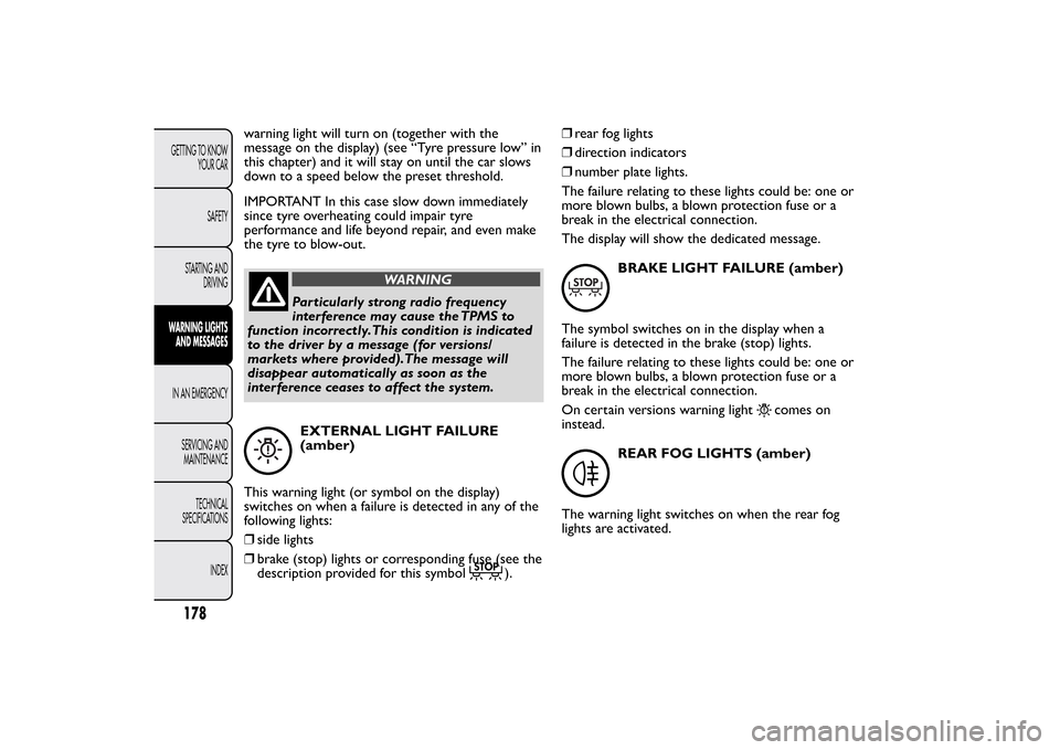
interference ceases to affect the system.EXTERNAL LIGHT FAILURE
(amber)
This warning light (or symbol on the display)
switches on when a failure is detected in any of the
following lights:
❒side lights
❒brake (stop) lights or corresponding fuse (see the
description provided for this symbol
).❒rear fog lights
❒direction indicators
❒number plate lights.
The failure relating to these lights could be: one or
more blown bulbs, a blown protection fuse or a
break in the electrical connection.
The display will show the dedicated message.
BRAKE LIGHT FAILURE (amber)
The symbol switches on in the display when a
failure is detected in the brake (stop) lights.
The failure relating to these lights could be: one or
more blown bulbs, a blown protection fuse or a
break in the electrical connection.
On certain versions warning light
comes on
instead.
REAR FOG LIGHTS (amber)
The warning light switches on when the rear fog
lights are activated.
178GETTING TO KNOW
YOUR CAR
SAFETY
STARTING AND
DRIVINGWARNING LIGHTS
AND MESSAGESIN AN EMERGENCY
SERVICING AND
MAINTENANCE
TECHNICAL
SPECIFICATIONS
INDEX
Page 184 of 299

The warning light on the instrument panel switches
on when the Cruise Control ring nut is turned to
ON.
The display will show the dedicated message.
POSSIBLE ICE ON ROAD
The outside temperature indicator starts flashing
when the outside temperature reaches or falls
below 3°C and the
symbol lights up on the
display to warn the driver of the possible presence
of ice on the road.
The display will show the dedicated message.
LIMITED RANGE
The display will show the dedicated message to
warn the driver that the car’s range is less
than 50 km.ASR SYSTEM
The ASR system can be turned off by pressing the
button ASR OFF. The display will show a specific
message to warn the driver that the system is off;
at the same time, the button LED will turn on.
When you press ASR OFF again, the button LED
will turn off and the display will show a specific
message to inform you that the system is on again.
SPEED LIMIT EXCEEDED
The display shows the dedicated message when the
car exceeds the set speed limit.
The S indication appears on the instrument panel
when the corresponding function is activated by
pressing the relevant control button. If the button
is pressed again the S indication goes out.
180GETTING TO KNOW
YOUR CAR
SAFETY
STARTING AND
DRIVINGWARNING LIGHTS
AND MESSAGESIN AN EMERGENCY
SERVICING AND
MAINTENANCE
TECHNICAL
SPECIFICATIONS
INDEX
CRUISE CONTROL (green) (for
versions/markets, where provided)
Turning the key to the MAR-ON position the
warning light switches on, but it should switch off
after a few seconds.
ENGAGEMENT OF SPORT FUNCTION
Page 187 of 299

WARNING
Alert other drivers that the car is
stationary in compliance with local
regulations: hazard warning lights, warning
triangle, etc . Any passengers on board should
leave the car, especially if it is heavily laden.
Passengers should stay away from on-coming
traffic while the wheel is being changed. On
hills or uneven roads, use chocks or
appropriate objects to block the wheels of the
car.
WARNING
The car's driving characteristics will be
modified with the space-saver wheel
fitted. Avoid sudden starting or stopping, sharp
or fast turns.The total life of a space-saver
wheel is approximately 3000 km, after which it
must be replaced by another wheel of the
same type. Never install a traditional tyre on a
rim designed to be used as a space-saver
wheel. Have the tyre repaired and refitted as
soon as possible. Using two or more space-
saver wheels at the same time is forbidden. Do
not grease the threads of bolts before fitting
them: they might slip out .
WARNING
The jack provided is only intended to
be used for replacing wheels on the car
with which it is supplied, or on same-model
vehicles. Never use the jack for other
purposes, such as lifting other car models.
Never use it for repair operations under the
car. Incorrectly positioning the jack may cause
the car to fall. Do not use the jack for loads
higher than the one shown on its label. Never
install snow chains on the space-saver wheel; if
a front tyre (driving wheel) is punctured and
you need to use snow chains, use a standard
wheel from the rear axle and install the
space-saver wheel on the rear axle. In this
way, with two normal drive wheels, it is
possible to use snow chains.
WARNING
Fit the hub cap correctly to prevent it
from coming free in motion. Never
tamper with the inflating valve. Never
introduce tools of any kind between rim and
tyre. Check tyre and space-saver wheel
pressures regularly, referring to the values
shown in the "Technical data" chapter.
183GETTING TO KNOW
YOUR CAR
SAFETY
STARTING AND
DRIVING
WARNING LIGHTS
AND MESSAGESIN AN
EMERGENCYSERVICING AND
MAINTENANCE
TECHNICAL
SPECIFICATIONS
INDEX
Page 190 of 299

❒fit handle R fig. 145 to operate the jack and raise
the car until the wheel is a few centimetres
above the ground;
❒fully loosen the fastening bolts and remove the
wheel.
❒make sure the contact surfaces between
space-saver wheel and hub are clean so that the
fastening bolts will not come loose;
❒fit the space-saver wheel aligning the openings S
fig. 146 with the corresponding centering pins T;
❒using the wrench provided, tighten the four
fastening bolts;
❒turn the jack handle R fig. 145 to lower the car
and remove the jack;
❒use the wrench provided to fully tighten the
bolts, passing alternately from one bolt to the
opposite one, as per the numerical sequence
illustrated in fig. 147.REFITTING THE STANDARD WHEEL
Following the procedure described previously, raise
the car and remove the space-saver wheel.
Versions with steel rims
Proceed as follows:
❒make sure the contact surfaces between standard
wheel and hub are clean so that the fastening
bolts will not come loose;
❒fit the standard wheel aligning the openings S
fig. 146 with the corresponding centering pins T;
❒using the wrench provided, tighten the fastening
bolts;
❒lower the car and remove the jack;
❒using the wrench provided, fully tighten the bolts
in the sequence shown in diagram fig. 147;
fig. 146
F0Q0396
fig. 147
F0Q0397
186GETTING TO KNOW
YOUR CAR
SAFETY
STARTING AND
DRIVING
WARNING LIGHTS
AND MESSAGES
IN AN
EMERGENCY
SERVICING AND
MAINTENANCE
TECHNICAL
SPECIFICATIONS
INDEX
Page 197 of 299

CHANGING A BULBGENERAL INSTRUCTIONS
❒Before changing a bulb check the contacts for
oxidation;
❒Burnt bulbs must be replaced by others of the
same type and power;
❒after replacing a headlight bulb, always check its
alignment;
❒when a light is not working, check that the
corresponding fuse is intact before changing
a bulb. For the location of fuses, refer to the
paragraph “If a fuse blows” in this section;
WARNING
Modifications or repairs to the electric
system that are not carried out
properly or do not take the system technical
specifications into account can cause
malfunctions leading to the risk of fire.
WARNING
Halogen bulbs contain pressurised gas,
in the case of breakage they may burst .
fig. 156
F0Q0512
193GETTING TO KNOW
YOUR CAR
SAFETY
STARTING AND
DRIVING
WARNING LIGHTS
AND MESSAGESIN AN
EMERGENCYSERVICING AND
MAINTENANCE
TECHNICAL
SPECIFICATIONS
INDEX
CYLINDER REPLACEMENT PROCEDURE
To replace the cylinder, proceed as follows:
❒disconnect coupling B fig. 156;
❒turn the cylinder to be replaced anticlockwise
and raise it;
❒fit the new cylinder and turn it clockwise;
❒connect coupling B to the cylinder and fit
transparent pipe A in the specific compartment.
Page 198 of 299

Halogen bulbs must be handled holding
the metallic part only.Touching the
transparent part of the bulb with your
fingers may reduce the intensity of the emitted
light and even reduce the lifespan of the bulb. In
case of accidental contact , wipe the bulb with
a cloth moistened with alcohol and let the bulb
dry.If possible, we recommend have bulbs
replaced by a Fiat Dealership.The
correct operation and aiming of the
outer lights are absolutely essential for the
safety of the car and of compliance with law.Due to the high supply voltage, gas
discharge bulbs (Bi-Xenon) (for
versions/markets, where provided) must
only be replaced by a specialist technician:
danger of death! Contact a Fiat Dealership.IMPORTANT When the weather is cold or damp
or after heavy rain or washing, the surface of
headlights or rear lights, may steam up and/or form
drops of condensation on the inside. This is a
natural phenomenon due to the difference in
temperature and humidity between the inside and
the outside of the glass which does not indicate
a fault and does not compromise the normal
operation of lighting devices. The mist disappears
quickly when the lights are turned on, starting from
the centre of the diffuser, extending progressively
towards the edges.
194GETTING TO KNOW
YOUR CAR
SAFETY
STARTING AND
DRIVING
WARNING LIGHTS
AND MESSAGES
IN AN
EMERGENCY
SERVICING AND
MAINTENANCE
TECHNICAL
SPECIFICATIONS
INDEX
Page 208 of 299

REPLACING INTERIOR BULBSFor the type of bulb and corresponding power
rating, see the paragraph "Changing a bulb".
FRONT ROOF LIGHT
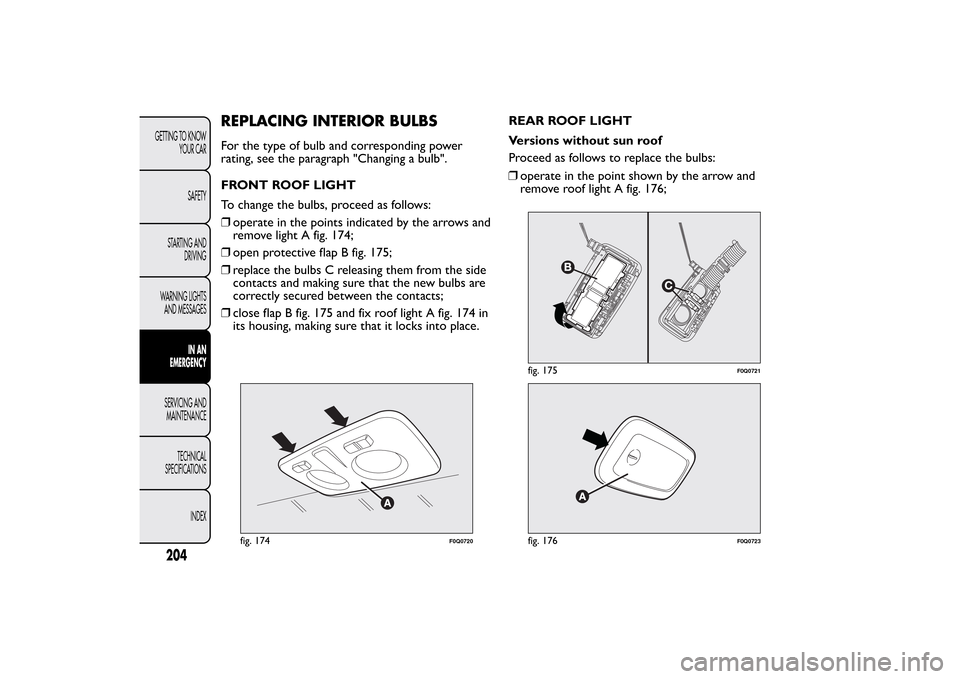
To change the bulbs, proceed as follows:
❒operate in the points indicated by the arrows and
remove light A fig. 174;
❒open protective flap B fig. 175;
❒replace the bulbs C releasing them from the side
contacts and making sure that the new bulbs are
correctly secured between the contacts;
❒close flap B fig. 175 and fix roof light A fig. 174 in
its housing, making sure that it locks into place.REAR ROOF LIGHT
Versions without sun roof
Proceed as follows to replace the bulbs:
fig. 174
F0Q0720
fig. 175
F0Q0721
fig. 176
F0Q0723
204GETTING TO KNOW
YOUR CAR
SAFETY
STARTING AND
DRIVING
WARNING LIGHTS
AND MESSAGES
IN AN
EMERGENCY
SERVICING AND
MAINTENANCE
TECHNICAL
SPECIFICATIONS
INDEX
❒operate in the point shown by the arrow and
remove roof light A fig. 176;
Page 215 of 299

Engine compartment fuse box next to the
battery
fig. 189(for versions/markets, where provided)
A second fuse box is located on the right-hand of
the engine compartment, next to the battery;
to reach it loosen the fixing screws and remove
cover A fig. 188.
The number identifying the electrical component
corresponding to each fuse is on the back of the
cover.
fig. 188
F0Q0816
fig. 189
F0Q0815
211GETTING TO KNOW
YOUR CAR
SAFETY
STARTING AND
DRIVING
WARNING LIGHTS
AND MESSAGESIN AN
EMERGENCYSERVICING AND
MAINTENANCE
TECHNICAL
SPECIFICATIONS
INDEX