2012 DODGE GRAND CARAVAN driver seat
[x] Cancel search: driver seatPage 320 of 643

Auto Unlock Doors
When ON is selected, all doors will unlock when the
vehicle is stopped and the transmission is in the PARK or
NEUTRAL position and the driver’s door is opened. To
make your selection, press and release the SELECT
button until a check-mark appears next to the feature
showing the system has been activated or the check-mark
is removed showing the system has been deactivated.
Remote Unlock Sequence
WhenDriver Door 1st Press is selected, only the driver’s
door will unlock on the first press of the Remote Keyless
Entry (RKE) transmitter UNLOCK button. When Driver
Door 1st Press is selected, you must press the RKE
transmitter UNLOCK button twice, to unlock the passen-
ger’s doors. When All Doors 1st Press is selected, all of
the doors will unlock on the first press of the RKE
transmitter UNLOCK button. To make your selection,
press and release the SELECT button until a check-mark appears next to the feature showing the system has been
activated or the check-mark is removed showing the
system has been deactivated.
RKE Linked To Memory
When this feature is selected the memory seat, mirror,
and radio settings will return to the memory set position
when the RKE transmitter UNLOCK button is pressed. If
this feature is not selected then the memory seat, mirror,
and radio settings can only return to the memory set
position using the door mounted switch. To make your
selection, press and release the SELECT button until a
check-mark appears next to the feature showing the
system has been activated or the check-mark is removed
showing the system has been deactivated.
Remote Start Comfort Sys.
When this feature is selected and the remote start is
activated, the heated steering wheel and driver heated
seat features will automatically turn on in cold weather.
4
UNDERSTANDING YOUR INSTRUMENT PANEL 317
Page 321 of 643
In warm weather, the driver vented seat feature will
automatically turn on when the remote start is activated.
These features will stay on through the duration of
remote start or until the key is turned to RUN. To make
your selection, press and release the SELECT button until
a check-mark appears next to the feature showing the
system has been activated or the check-mark is removed
showing the system has been deactivated.
Horn with Remote Lock
When this feature is selected, a short horn sound will
occur when the RKE transmitter LOCK button is pressed.
This feature may be selected with or without the Flash
Lamps with Lock feature. To make your selection, press
and release the SELECT button until a check-mark ap-
pears next to the feature showing the system has been
activated or the check-mark is removed showing the
system has been deactivated.
Flash Lamps with Lock
When ON is selected, the front and rear turn signals will
flash when the doors are locked or unlocked with the
RKE transmitter. This feature may be selected with or
without the sound horn on lock feature selected. To make
your selection, press and release the SELECT button until
a check-mark appears next to the feature showing the
system has been activated or the check-mark is removed
showing the system has been deactivated.
Headlamp Off Delay
When this feature is selected, the driver can choose to
have the headlights remain on for 0, 30, 60, or 90 seconds
when exiting the vehicle. To make your selection, scroll
up or down until the preferred setting is highlighted,
then press and release the SELECT button until a check-
mark appears next to the setting, showing that the setting
has been selected.
318 UNDERSTANDING YOUR INSTRUMENT PANEL
Page 323 of 643
Illuminated Approach
When this feature is selected, the headlights will activate
and remain on for up to 90 seconds when the doors are
unlocked with the RKE transmitter. To make your selec-
tion, scroll up or down until the preferred setting is
highlighted, then press and release the SELECT button
until a check-mark appears next to the setting, showing
that the setting has been selected.
Flashers with Sliding Door
When this feature is selected the signal lamps activate
when power or manual sliding doors are in operation,
signaling other drivers that someone may be exiting or
entering the vehicle. To make your selection, press and
release the SELECT button until a check-mark appears
next to the feature showing the system has been activated
or the check-mark is removed showing the system has
been deactivated.
Easy Entry/Exit Seat
This feature provides automatic driver seat positioning to
enhance driver mobility when entering and exiting the
vehicle. To make your selection, press and release the
SELECT button until a check-mark appears next to the
feature showing the system has been activated or the
check-mark is removed showing the system has been
deactivated.
NOTE:The seat will return to the memorized seat
location (if Recall Memory with Remote Key Unlock is set
to ON) when the RKE transmitter is used to unlock the
door. Refer to “Driver Memory Seat” in “Understanding
The Features Of Your Vehicle” for further information.
Tilt Mirror In Reverse
When this feature is selected and the vehicle is placed in
a reverse gear, the driver’s side mirror will tilt downward
to allow the driver to see into the previous blind spot and
avoid objects in close proximity to the rear of the vehicle.
320 UNDERSTANDING YOUR INSTRUMENT PANEL
Page 403 of 643
When rear controls are locked by the front system, the
lock symbol on the temperature knob is illuminated, and
the rear overhead adjustments are inoperable.
Rear Mode Control
Headliner ModeAir comes from the outlets in the headliner. Each of
these outlets can be individually adjusted to direct
the flow of air. Moving the air vanes of the outlets to one
side will shut off the airflow.
Bi-Level Mode Air comes from both the headliner outlets and the
floor outlets.
NOTE: In many temperature positions, the Bi-Level
mode is designed to provide cooler air out of the head-
liner outlets and warmer air from the floor outlets. Floor Mode
Air comes from the floor outlets.
Automatic Temperature Control (ATC) — If
Equipped
•
Front Three-Zone ATC allows both driver and front
passenger seat occupant, and rear seat occupants to
select individual comfort settings.
•When occupants in the vehicle select the AUTO mode
operation, a comfort temperature can be set by using
the temperature up and down buttons, and the auto
blower operation will be set automatically.
•The system can be controlled manually, if desired.
•SYNC feature links the controls for all three zones,
allowing one comfort setting (driver setting) for the
cabin, if desired.
400 UNDERSTANDING YOUR INSTRUMENT PANEL
Page 404 of 643
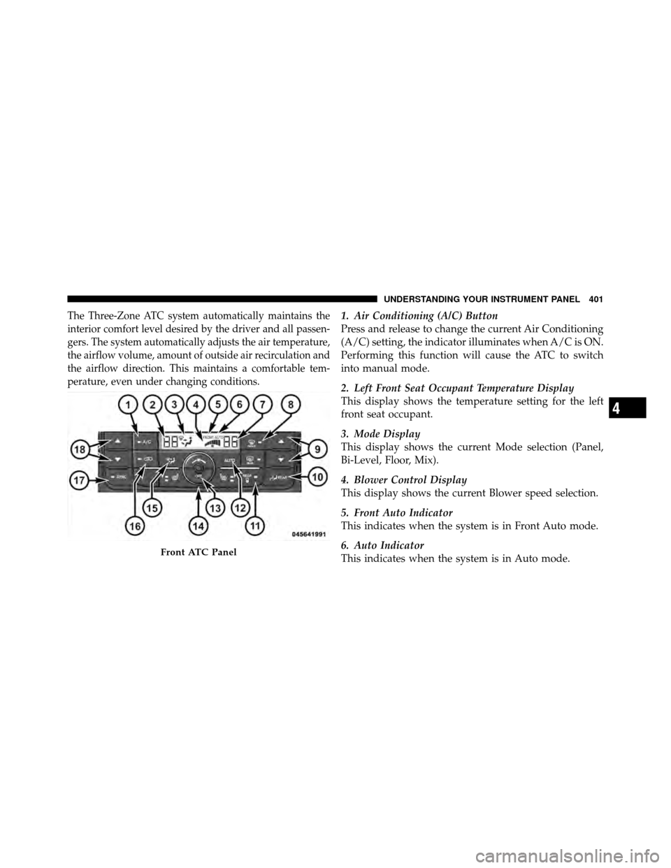
The Three-Zone ATC system automatically maintains the
interior comfort level desired by the driver and all passen-
gers. The system automatically adjusts the air temperature,
the airflow volume, amount of outside air recirculation and
the airflow direction. This maintains a comfortable tem-
perature, even under changing conditions.1. Air Conditioning (A/C) Button
Press and release to change the current Air Conditioning
(A/C) setting, the indicator illuminates when A/C is ON.
Performing this function will cause the ATC to switch
into manual mode.
2. Left Front Seat Occupant Temperature Display
This display shows the temperature setting for the left
front seat occupant.
3. Mode Display
This display shows the current Mode selection (Panel,
Bi-Level, Floor, Mix).
4. Blower Control Display
This display shows the current Blower speed selection.
5. Front Auto Indicator
This indicates when the system is in Front Auto mode.
6. Auto Indicator
This indicates when the system is in Auto mode.
Front ATC Panel
4
UNDERSTANDING YOUR INSTRUMENT PANEL 401
Page 407 of 643
1. Mode Display
This display shows the current Mode selection.
2. Rear Temperature Display
This display shows the temperature setting for the rear
seat occupants.
3. Blower Control Display
This display shows the current Blower speed selection.
4. Rear Auto Indicator
This indicates when the system is in Rear Auto mode.
Automatic Operation
1. Press the AUTO button on the front ATC Panel and the
words Front Auto will illuminate in the front ATC
display, along with two temperatures for the driver and
front passenger. The system will then automatically
regulate the amount of airflow.2. Next, adjust the temperature you would like the
system to maintain, by adjusting the driver, front passen-
ger, and rear seat rotary temperature knobs. Once the
desired temperature is displayed, the system will achieve
and automatically maintain that comfort level.
3. When the system is set up for your comfort level, it is
not necessary to change the settings. You will experience
the greatest efficiency by simply allowing the system to
function automatically.
NOTE:
•It is not necessary to move the temperature settings for
cold or hot vehicles. The system automatically adjusts
the temperature, mode and fan speed to provide
comfort as quickly as possible.
•The temperature can be displayed in English or Metric
units by selecting the “Display Units of Measure in”
404 UNDERSTANDING YOUR INSTRUMENT PANEL
Page 462 of 643
3. Subtract the combined weight of the driver and pas-
sengers from XXX lbs or XXX kg.
4. The resulting figure equals the available amount of
cargo and luggage load capacity. For example, if “XXX”
amount equals 1,400 lbs (635 kg) and there will be five
150 lb (68 kg) passengers in your vehicle, the amount of
available cargo and luggage load capacity is 650 lbs
(295 kg) (since 5 x 150 = 750, and 1400 – 750 = 650 lbs
[295 kg]).
5. Determine the combined weight of luggage and cargo
being loaded on the vehicle. That weight may not safely
exceed the available cargo and luggage load capacity
calculated in Step 4.
6. If your vehicle will be towing a trailer, load from your
trailer will be transferred to your vehicle. Consult this
manual to determine how this reduces the available
cargo and luggage load capacity of your vehicle.NOTE:
•The following table shows examples on how to calcu-
late total load, cargo/luggage, and towing capacities
of your vehicle with varying seating configurations
and number and size of occupants. This table is for
illustration purposes only and may not be accurate for
the seating and load carry capacity of your vehicle.
•For the following example, the combined weight of
occupants and cargo should never exceed 865 lbs
(392 kg).
5
STARTING AND OPERATING 459
Page 495 of 643
•If the gas cap is not tightened properly, the MIL may
come on. Be sure the gas cap is tightened every time
the vehicle is refueled.
Loose Fuel Filler Cap Message
If the vehicle diagnostic system determines that the fuel
filler cap is loose, improperly installed, or damaged, a
“gASCAP” message will display in the odometer or a
“CHECK GASCAP” message will be displayed in the
Electronic Vehicle Information Center (EVIC). Refer to
“Electronic Vehicle Information Center” in “Understand-
ing Your Instrument Panel” for further information.
Tighten the fuel filler cap until a “clicking” sound is heard.
This is an indication that the fuel filler cap is properly
tightened. Refer to “Onboard Diagnostic System” in
“Maintaining Your Vehicle” for further information.
If the problem continues, the message will appear the
next time the vehicle is started. See your authorized
dealer as soon as possible.
VEHICLE LOADING
As required by National Highway Traffic Safety Admin-
istration regulations, your vehicle has a certification label
affixed to the driver’s side door or B-Pillar.
If seats are removed for carrying cargo, do not exceed the
specified GVWR and GAWR.
Vehicle Certification Label
Your vehicle has a Vehicle Certification Label attached to
the driver’s door B-Pillar.
The label contains the following information:
•Name of manufacturer
•Month and year of manufacture
•Gross Vehicle Weight Rating (GVWR)
•Gross Axle Weight Rating (GAWR) — Front
•Gross Axle Weight Rating (GAWR) — Rear
492 STARTING AND OPERATING