2012 DODGE DURANGO power steering
[x] Cancel search: power steeringPage 3 of 140

INTRODUCTION/WELCOMEWelcome From Chrysler Group LLC....2
CONTROLS AT A GLANCEDriver Cockpit...............4
Instrument Cluster .............6
GETTING STARTEDKeyFob...................8
Remote Start...............10
Keyless Enter-N-Go™ ..........11
Theft Alarm ................14
Seat Belt .................14
Supplemental Restraint System
(SRS) — Air Bags ............15
Child Restraints .............16
Front Seats ................19
Rear Seats ................21
Power Folding Third Row
Head Restraints .............23
Heated/Ventilated Seats .........23
Heated Steering Wheel ..........25
Tilt/Telescoping Steering Column ....26
OPERATING YOUR VEHICLEEngine Break-In Recommendations . . . 27
Headlight Switch.............27
Turn Signal/Wiper/Washer/High Beam
Lever ...................28
Auto Dimming Mirrors ..........29
Speed Control ..............30
Electronic Range Selection (ERS) ....34
Automatic Temperature Controls (ATC).. 35
Parksense®Rear Park Assist .......36
Parkview®Rear Back-Up Camera ....37
Blind Spot Monitoring ..........37
Power Sunroof ..............38
Wind Buffeting ..............39
ELECTRONICSYour Vehicle's Sound System ......40
Media Center 130 (Sales Code RES) . . 42
Media Center 130 With Satellite Radio
(Sales Code RES + RSC) .........44
Media Center 430/430N (Sales Code
RBZ/RHB) ................46
Media Center 730N
(Sales Code RHR) ............55
Sirius XM™ Satellite Radio/Travel Link.. 65
Steering Wheel Audio Controls ......68
iPod
®/USB/MP3 Control .........68
Uconnect™ Phone ............70
Uconnect™ Voice Command .......72
Bluetooth
®Streaming Audio .......74
Video Entertainment System (VES)™ . . 74 Electronic Vehicle Information
Center (EVIC)
...............76
Programmable Features .........77
Universal Garage Door Opener
(HomeLink
®) ...............77
Power Inverter ..............80
Power Outlet ...............81
OFF-ROAD CAPABILITIESAll-Wheel Drive Operation ........83
UTILITYRoof Luggage Rack............85
Trailer Towing Weights (Maximum
Trailer Weight Ratings) ..........86
Tow/Haul Mode ..............87
Recreational Towing (Behind
Motorhome, Etc.) .............87
WHAT TO DO IN EMERGENCIES24-Hour Towing Assistance .......89
Instrument Cluster Warning Lights . . . 89
If Your Engine Overheats .........92
Jacking And Tire Changing ........94
Battery Location ............ 103
Jump-Starting ............. 103
Emergency Tow Hooks ......... 105
Shift Lever Override .......... 106
Towing A Disabled Vehicle ....... 107
Event Data Recorder (EDR) ...... 108
MAINTAINING YOUR VEHICLEOpening The Hood........... 109
Fuel Door Release ........... 109
Engine Compartment .......... 111
Fluids And Capacities ......... 113
Maintenance Chart ........... 115
Fuses .................. 118
Tire Pressures .............. 121
Wheel And Wheel Trim Care ...... 122
Exterior Bulbs ............. 122
CONSUMER ASSISTANCEChrysler Group LLC Customer Center. . 123Chrysler Canada Inc. Customer Center...123Assistance For The Hearing Impaired. . 123
Publications Ordering ......... 123
Reporting Safety Defects In
The 50 United States And
Washington, D.C. ............ 124
MOPAR ACCESSORIESAuthentic Accessories By MOPAR®. . 125
INDEX................. 126
FAQ (How To?)Frequently Asked Questions ...... 129
TABLE OF CONTENTS
Page 7 of 140

A. Headlight Switch pg. 27
B. Turn Signal/Wiper/Washer/High BeamsLever (behind steering wheel) pg. 28
C. Instrument Cluster pg. 6
D. Electronic Vehicle Information Center (EVIC) Display pg. 76
E. Ignition Switch (behind steering wheel)
F. Audio System (touch-screen-radio shown) pg. 40
G. Climate Controls pg. 35 H. SWITCH PANEL
− Electronic Stability Control pg. 91
− Tow/Haul
− Heated Steering Wheel pg. 25
− Hazard Switch
− Power Inverter pg. 80
− ParkSense
®pg. 36
− Power Folding Third Row Head Restraints pg. 23
I. Transmission Gear Selector J. Power Outlet pg. 81
K. Speed Control pg. 30
L. EVIC Controls pg. 76
M. Fuel Door Release pg. 109
N. Parking Brake Release
O. Power Mirrors
P. Power Windows
Q. Power Door Locks
R. Driver's Memory Buttons pg. 19
CONTROLS AT A GLANCE
5
Page 21 of 140

FRONT SEATS
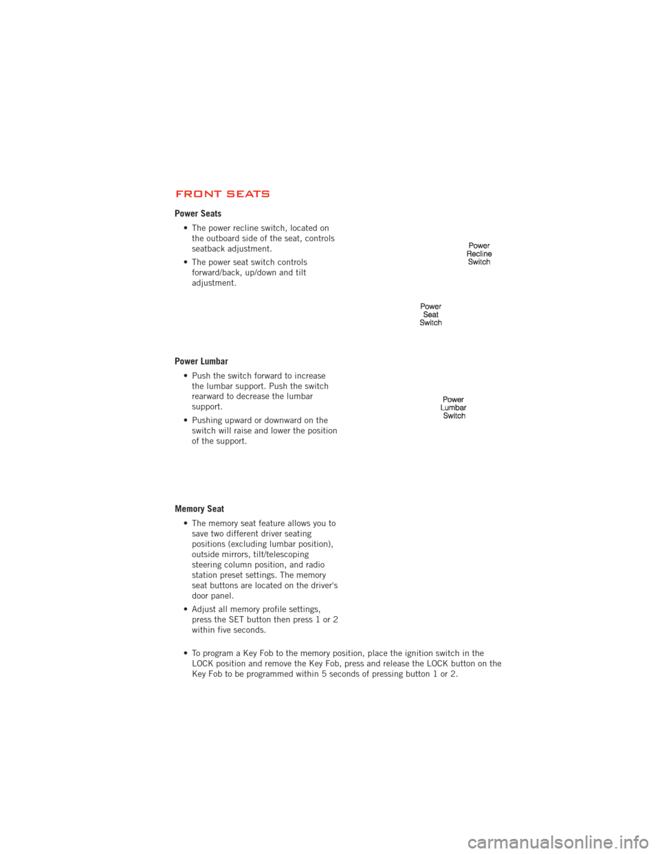
Power Seats
• The power recline switch, located onthe outboard side of the seat, controls
seatback adjustment.
• The power seat switch controls forward/back, up/down and tilt
adjustment.
Power Lumbar
• Push the switch forward to increasethe lumbar support. Push the switch
rearward to decrease the lumbar
support.
• Pushing upward or downward on the switch will raise and lower the position
of the support.
Memory Seat
• The memory seat feature allows you tosave two different driver seating
positions (excluding lumbar position),
outside mirrors, tilt/telescoping
steering column position, and radio
station preset settings. The memory
seat buttons are located on the driver's
door panel.
• Adjust all memory profile settings, press the SET button then press 1 or 2
within five seconds.
• To program a Key Fob to the memory position, place the ignition switch in the LOCK position and remove the Key Fob, press and release the LOCK button on the
Key Fob to be programmed within 5 seconds of pressing button 1 or 2.
GETTING STARTED
19
Page 28 of 140

TILT/TELESCOPING STEERING COLUMN
Manual - Tilt/Telescoping Steering Column
• The tilt/telescoping control handle islocated below the steering wheel at the
end of the steering column.
• Push the handle down to unlock the steering column.
• To tilt the steering column, move the steering wheel upward or downward as
desired. To lengthen or shorten the
steering column, pull the steering
wheel outward or push it inward as
desired.
• Pull up on the handle to lock the column firmly in place.
Power - Tilt/Telescoping Steering Column
• The power tilt/telescoping steering control is located below the turn
signal/wiper/washer/high beam lever on
the steering column.
• To tilt the steering column, move the power tilt/telescoping control up or
down as desired. To lengthen or
shorten the steering column, pull the
control toward you or push the control
away from you as desired.
WARNING!
• Do not adjust the steering wheel while driving. The tilt/telescopingadjustment must be locked while driving. Adjusting the steering wheel while
driving or driving without the tilt/telescoping adjustment locked could cause
the driver to lose control of the vehicle. Failure to follow this warning may
result in you and others being severely injured or killed.
• Moving the steering column while the vehicle is moving is dangerous. Without a stable steering column, you could lose control of the vehicle and
have a collision. Adjust the column only while the vehicle is stopped.
GETTING STARTED
26
Page 116 of 140

ComponentFluid, Lubricant, or Genuine
PartCapacities
Automatic Transmission MOPAR
®ATF+4®
Automatic Transmission
Fluid or equivalent
licensed ATF+4
®product. —
Transfer Case – 3.6L
Engine Shell Automatic
Transmission Fluid 3353
or equivalent. —
Transfer Case – 5.7L
Engine MOPAR
®ATF+4®
Automatic Transmission
Fluid or equivalent
licensed ATF+4
®product.—
Axle Differential
(Front/Rear) We recommend you use
MOPAR
®GL-5 Synthetic
Axle Lubricant
SAE 75W-85. —
Brake Master Cylinder MOPAR
®DOT 3 and SAE
J1703 should be used or
equivalent. If DOT 3 is not
available, then DOT 4 is
acceptable. Use only
recommended brake fluids. —
Power Steering Reservoir –
3.6L Engine MOPAR
®Hydraulic Fluid
or equivalent meeting
MS-11655, such as Fuchs
EG ZH 3044 or Pentosin
CHF 11s. —
Power Steering Reservoir –
5.7L Engine MOPAR
®Power Steering
Fluid +4, MOPAR®
ATF+4®Automatic
Transmission Fluid meeting
MS-9602 or equivalent
licensed ATF+4
®product. —
Fuel Selection 3.6L, 5.7L 87 Octane acceptable. 89 Octane recommended
for 5.7L.24 Gallons (91 Liters)
(Approximate)
E-85 Flexible Fuel – 3.6L Engine Only
CAUTION!
Only vehicles with the E-85 fuel filler door label or a yellow gas cap can operate
on E-85.
• Refer to your Owner's Manual on the DVD for further details.
MAINTAINING YOUR VEHICLE
114
Page 121 of 140

Integrated Power Module (fuses)
The integrated power module is located on the right side of the engine compartment.
This center contains cartridge fuses and mini fuses. A description of each fuse and
component may be stamped on the inside cover, otherwise the cavity number of each
fuse is stamped on the inside cover that corresponds to the following chart.
Cavity Cartridge Fuse Mini FuseDescription
J01 40 Amp Green –
J02 30 Amp Pink Power Liftgate Module
J03 30 Amp Pink Trailer Tow
J04 25 Amp Natural Driver Door Node
J05 25 Amp Natural Passenger Door Node
J06 40 Amp Green Antilock Brakes Pump/Stability
Control System
J07 30 Amp Pink Antilock Brakes Valve/Stability Control
System
J08 40 Amp Green Power Seat
J09 30 Amp Pink E-Brake
J10 30 Amp Pink Headlamp Wash Relay Contact
J11 30 Amp Pink Drive Train Control Module
J12 30 Amp Pink Rear Defroster
J13 60 Amp Yellow Main Ignition Off Draw (IOD)
J14 20 Amp Blue Trailer Tow Lamps/Park Lamps
J15 40 Amp Green Front Cabin Fan/Blower
J17 40 Amp Green Starter Motor Solenoid
J18 20 Amp Blue Powertrain Control Module/Powertrain
Control Module Transmission Range
J19 60 Amp Yellow Radiator Fan Motor HI/Radiator Fan
Motor Low
J20 30 Amp Pink Front Wiper
J21 20 Amp Blue Front/Rear Washer Control
J22 25 Amp Natural Sunroof Module
M1 15 Amp Blue Stop Lamp
M2 20 Amp Yellow –
M3 20 Amp Yellow Liftgate Unlock/DRL Relay/Third Row
Headrest
M5 25 Amp Natural 115V AC Power Inverter
M6 20 Amp Yellow Rain Sensor/Cigar Lighter
M7 20 Amp Yellow Power Outlet #2 (Switchable)
M8 20 Amp Yellow Front Heated Seat & Steering Wheel
M9 20 Amp Yellow Rear Heated Seats
M10 15 Amp Blue Video/Universal Garage Door
Opener/Hands Free/Vanity Lamps
MAINTAINING YOUR VEHICLE
119
Page 122 of 140

Cavity Cartridge Fuse Mini FuseDescription
M11 10 Amp Red Heating, Ventilation & Air
Conditioning (Climate Control
System)
M12 30 Amp Green Radio/Amplifier
M13 20 Amp Yellow Instrument Cluster/Ignition Module
M14 20 Amp Yellow Back Up Camera
M15 20 Amp Yellow Power Seat Module(s)/Adaptive Cruise
Control/Audio Telematics/Daytime
Running Lights Relay/Instrument
Cluster
M16 10 Amp Red Occupant Restraint Controller
M18 15 Amp Blue Stop Lamp
M19 25 Amp Natural Automatic Shutdown 1 and 2
M20 15 Amp Blue Instrument Cluster/Steering Wheel
Switches
M21 20 Amp Yellow Automatic Shutdown 3
M22 10 Amp Red Horns (Low/High) – Right
M23 10 Amp Red Horns (Low/High) – Left
M24 25 Amp Natural Rear Wiper
M25 20 Amp Yellow Fuel Pump Motor Output
M26 10 Amp Red Switch Bank/Interior Lighting
M27 10 Amp Red Ignition Switch/Wireless Control
Module/Keyless Entry Module
M28 15 Amp Blue Powertrain Controller/Transmission
Controller
M29 10 Amp Red Tire Pressure Monitor
M30 15 Amp Blue J1962 Diag Connector
M31 20 Amp Yellow Backup Lamps
M32 10 Amp Red Occupant Restraint Controller
M33 10 Amp Red Powertrain Controller/Transmission
Controller
M34 10 Amp Red Park Assist Module/Climate Control
System Module/IR Sensor/Compass
Module
M35 15 Amp Blue LH Rear Parklamps
M36 20 Amp Yellow Power Outlet
M37 10 Amp Red Antilock Brakes/Stability Control
System Module/Stoplamp Switch
Sensor
M38 25 Amp Natural All Door Lock &Unlock
MAINTAINING YOUR VEHICLE
120
Page 123 of 140

CAUTION!
• When installing the integrated power module cover, it is important to ensurethe cover is properly positioned and fully latched. Failure to do so may allow
water to get into the integrated power module and possibly result in a
electrical system failure.
• When replacing a blown fuse, it is important to use only a fuse having the correct amperage rating. The use of a fuse with a rating other than indicated
may result in a dangerous electrical system overload. If a properly rated fuse
continues to blow, it indicates a problem in the circuit that must be
corrected.
TIRE PRESSURES
• Check the inflation pressure of each tire, including the spare tire, at least monthlyand inflate to the recommended pressure for your vehicle.
• The tire pressures recommended for your vehicle are found on the “Tire and Loading Information” label located on the driver’s side door opening.
NOTE: Refer to the Owner's Manual on the
DVD for more information regarding tire
warnings and instructions.
WARNING!
• Overloading of your tires is dangerous. Overloading can cause tire failure, affect vehicle handling, and increase your stopping distance. Use tires of the
recommended load capacity for your vehicle. Never overload them.
• Improperly inflated tires are dangerous and can cause collisions. Under-inflation is the leading cause of tire failure and may result in severe
cracking, component separation, or “blow out”. Over-inflation reduces a tire’s
ability to cushion shock. Objects on the road and chuck holes can cause
damage that results in tire failure. Unequal tire pressures can cause steering
problems. You could lose control of your vehicle. Over-inflated or
under-inflated tires can affect vehicle handling and can fail suddenly,
resulting in loss of vehicle control.
MAINTAINING YOUR VEHICLE
121