2012 DODGE DURANGO park assist
[x] Cancel search: park assistPage 3 of 140

INTRODUCTION/WELCOMEWelcome From Chrysler Group LLC....2
CONTROLS AT A GLANCEDriver Cockpit...............4
Instrument Cluster .............6
GETTING STARTEDKeyFob...................8
Remote Start...............10
Keyless Enter-N-Go™ ..........11
Theft Alarm ................14
Seat Belt .................14
Supplemental Restraint System
(SRS) — Air Bags ............15
Child Restraints .............16
Front Seats ................19
Rear Seats ................21
Power Folding Third Row
Head Restraints .............23
Heated/Ventilated Seats .........23
Heated Steering Wheel ..........25
Tilt/Telescoping Steering Column ....26
OPERATING YOUR VEHICLEEngine Break-In Recommendations . . . 27
Headlight Switch.............27
Turn Signal/Wiper/Washer/High Beam
Lever ...................28
Auto Dimming Mirrors ..........29
Speed Control ..............30
Electronic Range Selection (ERS) ....34
Automatic Temperature Controls (ATC).. 35
Parksense®Rear Park Assist .......36
Parkview®Rear Back-Up Camera ....37
Blind Spot Monitoring ..........37
Power Sunroof ..............38
Wind Buffeting ..............39
ELECTRONICSYour Vehicle's Sound System ......40
Media Center 130 (Sales Code RES) . . 42
Media Center 130 With Satellite Radio
(Sales Code RES + RSC) .........44
Media Center 430/430N (Sales Code
RBZ/RHB) ................46
Media Center 730N
(Sales Code RHR) ............55
Sirius XM™ Satellite Radio/Travel Link.. 65
Steering Wheel Audio Controls ......68
iPod
®/USB/MP3 Control .........68
Uconnect™ Phone ............70
Uconnect™ Voice Command .......72
Bluetooth
®Streaming Audio .......74
Video Entertainment System (VES)™ . . 74 Electronic Vehicle Information
Center (EVIC)
...............76
Programmable Features .........77
Universal Garage Door Opener
(HomeLink
®) ...............77
Power Inverter ..............80
Power Outlet ...............81
OFF-ROAD CAPABILITIESAll-Wheel Drive Operation ........83
UTILITYRoof Luggage Rack............85
Trailer Towing Weights (Maximum
Trailer Weight Ratings) ..........86
Tow/Haul Mode ..............87
Recreational Towing (Behind
Motorhome, Etc.) .............87
WHAT TO DO IN EMERGENCIES24-Hour Towing Assistance .......89
Instrument Cluster Warning Lights . . . 89
If Your Engine Overheats .........92
Jacking And Tire Changing ........94
Battery Location ............ 103
Jump-Starting ............. 103
Emergency Tow Hooks ......... 105
Shift Lever Override .......... 106
Towing A Disabled Vehicle ....... 107
Event Data Recorder (EDR) ...... 108
MAINTAINING YOUR VEHICLEOpening The Hood........... 109
Fuel Door Release ........... 109
Engine Compartment .......... 111
Fluids And Capacities ......... 113
Maintenance Chart ........... 115
Fuses .................. 118
Tire Pressures .............. 121
Wheel And Wheel Trim Care ...... 122
Exterior Bulbs ............. 122
CONSUMER ASSISTANCEChrysler Group LLC Customer Center. . 123Chrysler Canada Inc. Customer Center...123Assistance For The Hearing Impaired. . 123
Publications Ordering ......... 123
Reporting Safety Defects In
The 50 United States And
Washington, D.C. ............ 124
MOPAR ACCESSORIESAuthentic Accessories By MOPAR®. . 125
INDEX................. 126
FAQ (How To?)Frequently Asked Questions ...... 129
TABLE OF CONTENTS
Page 30 of 140

Instrument Panel Dimmer
• Rotate the dimmer control to the extreme bottom position to fully dim theinstrument panel lights and prevent the interior lights from illuminating when a
door is opened.
• Rotate the dimmer control up to increase the brightness of the instrument panel when the parking lights or headlights are on.
• Rotate the dimmer control up to the next detent position to fully brighten the odometer and radio when the parking lights or headlights are on. Refer to your
Media Center/Radio User Manual on the DVD for display dimming.
• Rotate the dimmer control up to the last detent position to turn on the interior lighting.
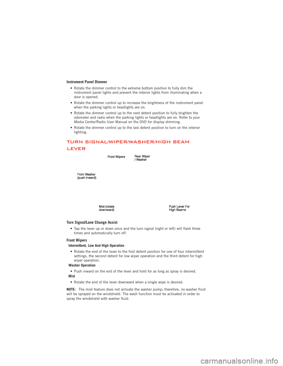
TURN SIGNAL/WIPER/WASHER/HIGH BEAM
LEVER
Turn Signal/Lane Change Assist
• Tap the lever up or down once and the turn signal (right or left) will flash threetimes and automatically turn off.
Front Wipers
Intermittent, Low And High Operation
• Rotate the end of the lever to the first detent position for one of four intermittent settings, the second detent for low wiper operation and the third detent for high
wiper operation.
Washer Operation
• Push inward on the end of the lever and hold for as long as spray is desired.
Mist
• Rotate the end of the lever downward when a single wipe is desired.
NOTE: The mist feature does not activate the washer pump; therefore, no washer fluid
will be sprayed on the windshield. The wash function must be activated in order to
spray the windshield with washer fluid.
OPERATING YOUR VEHICLE
28
Page 38 of 140

Rear Temperature Controls
• The rear controls for the ATC System are located in the headliner, near the centerof the vehicle.
• The rear temperature controls can be turned on two ways: • Press the REAR control button on the front temperature controls and adjust to the desired rear temperature.
• Rotate the Rear Temperature Control or the Rear Blower Control knobs on the rear temperature controls.
• Press the REAR button and then the OFF button on the front temperature controls to turn the rear controls off.
PARKSENSE®REAR PARK ASSIST
• The four ParkSense®sensors, located in the rear fascia/bumper, monitor the area
behind the vehicle that is within the sensors’ field of view.
• When an object is detected within two meters behind the rear bumper while the vehicle is in REVERSE, a warning will display in the Electronic Vehicle Information
Center (EVIC) and a chime will sound (when Sound and Display is selected from
the Customer Programmable Features section of the EVIC). As the vehicle moves
closer to the object, the chime rate will change from slow, to fast, to continuous.
Cleaning the ParkSense® Sensors
• If “CLEAN PARK ASSIST SENSORS” appears in the Electronic Vehicle InformationCenter (EVIC), clean the ParkSense®sensors with water, car wash soap and a soft
cloth. Do not use rough or hard cloths. Do not scratch or poke the sensors.
Otherwise, you could damage the sensors.
NOTE: When the Instrument Cluster reads either Clean Sensor or Blinded, please clean
off the bumper sensors to see if the condition is corrected.
OPERATING YOUR VEHICLE
36
Page 79 of 140

PROGRAMMABLE FEATURES
Electronic Vehicle Information Center (EVIC)
• The EVIC can be used to program the following Personal Settings. Press the UPor DOWNbutton until System Setup displays, then press the SELECTbutton. Scroll through the settings using the UP or DOWN buttons. Press the
SELECTbutton to change the setting. Press the BACK button to scroll back to
a previous menu or sub menu.
• Select Language • Illuminated Approach
• Nav – Turn By Turn • Hill Start Assist (HSA)
• Auto Unlock Doors • Display ECO Symbol
• Remote Unlock Sequence • Keyless Enter-N-Go™
• RKE Linked To Memory • Gauge Glow Rings
• Remote Start Comfort Sys. • Auto High Beams
• Horn with Remote Lock • Intermittent Wiper
• Horn With Remote Start • Blind Spot Alert
• Flash Lamps With Lock • Forward Collision Warning
• Headlamp Off Delay • Park Assist System
• Headlamps with Wipers • Display Units of Measure In:
• Easy Entry/Exit Seat • Liftgate Chime
• Tilt Mirror in Reverse • Calibrate Compass
• Key-Off Power Delay • Compass Variance
UNIVERSAL GARAGE DOOR OPENER
(HomeLink
®)
• HomeLink®replaces up to three hand-held transmitters that operate devices such
as garage door openers, motorized gates, lighting or home security systems. The
HomeLink
®unit is powered by your vehicles 12 Volt battery.
• The HomeLink
®buttons that are located in the overhead console or sunvisor
designate the three different HomeLink®channels.
• The HomeLink
®indicator is located above the center button.
ELECTRONICS
77
Page 80 of 140

Before You Begin Programming HomeLink®
• Be sure that your vehicle is parkedoutside of the garage before you begin
programming.
• For more efficient programming and accurate transmission of the
radio-frequency signal it is
recommended that a new battery be
placed in the hand-held transmitter of
the device that is being programmed to
the HomeLink
®system.
• Erase all channels before you begin programming. To erase the channels, place the ignition switch into the ON/RUN position, then press and hold the two outside
HomeLink
®buttons (I and III) for up 20 seconds or until the red indicator flashes.
NOTE:
• Erasing all channels should only be performed when programming HomeLink
®for the
first time. Do not erase channels when programming additional buttons.
• If you have any problems, or require assistance, please call toll-free 1–800–355– 3515 or, on the Internet at www.HomeLink.com for information or assistance.
Programming A Rolling Code
• For programming Garage Door Openers that were manufactured after 1995. TheseGarage Door Openers can be identified by the “LEARN” or “TRAIN” button located
where the hanging antenna is attached to the Garage Door Opener. It is NOT the
button that is normally used to open and close the door. The name and color of the
button may vary by manufacturer.
• Place the ignition switch into the ON/RUN position.
• Place the hand-held transmitter 1 to 3 in (3 to 8 cm) away from the HomeLink
®
button you wish to program while keeping the HomeLink®indicator light in view.
• Simultaneously press and hold both the HomeLink
®button you want to program
and the hand-held transmitter button.
• Continue to hold both buttons and observe the indicator light. The Homelink
®
indicator will flash slowly and then rapidly after Homelink®has received the
frequency signal from the hand-held transmitter. Release both buttons after the
indicator light changes from slow to rapid.
• At the garage door opener motor (in the garage), locate the “LEARN” or “TRAINING” button. This can usually be found where the hanging antenna wire is
attached to the garage door opener motor. Firmly press and release the “LEARN”
or “TRAINING” button.
NOTE: You have 30 seconds in which to initiate the next step after the LEARN button
has been pressed.
ELECTRONICS
78
Page 105 of 140

BATTERY LOCATION
• The battery in your vehicle is located under the passenger's front seat. Remotebattery posts are located on the right side of the engine compartment for
jump-starting.
JUMP-STARTING
• If your vehicle has a discharged battery it can be jump-started using a set ofjumper cables and a battery in another vehicle or by using a portable battery
booster pack.
• Jump-starting can be dangerous if done improperly so please follow the procedures in this section carefully.
NOTE: When using a portable battery booster pack follow the manufacturer’s operating
instructions and precautions.
Preparations for Jump-Start
• The battery in your vehicle is located under the passengers front seat. There
are remote locations under the hood to
assist in jump starting.
• Set the parking brake, shift the automatic transmission into PARK and
turn the ignition to OFF.
• Turn off the heater, radio, and all unnecessary electrical accessories.
• Remove the protective cover over the remote positive (+) battery post. Pull
upward on the cover to remove it.
• If using another vehicle to jump-start the battery, park the vehicle within the jumper cables reach, set the parking brake and make sure the ignition is OFF.
Jump-Starting Procedure
• Connect the positive (+)end of the jumper cable to the remote positive (+)post of
the discharged vehicle.
• Connect the opposite end of the positive (+)jumper cable to the positive (+)post
of the booster battery.
• Remove the protective cap from the negative jump post. Connect the negative end (-) of the jumper cable to the negative (-)post of the booster battery.
• Connect the opposite end of the negative (-)jumper cable to the remote negative
(-) post of the vehicle with the discharged battery.
WHAT TO DO IN EMERGENCIES
103
Page 122 of 140

Cavity Cartridge Fuse Mini FuseDescription
M11 10 Amp Red Heating, Ventilation & Air
Conditioning (Climate Control
System)
M12 30 Amp Green Radio/Amplifier
M13 20 Amp Yellow Instrument Cluster/Ignition Module
M14 20 Amp Yellow Back Up Camera
M15 20 Amp Yellow Power Seat Module(s)/Adaptive Cruise
Control/Audio Telematics/Daytime
Running Lights Relay/Instrument
Cluster
M16 10 Amp Red Occupant Restraint Controller
M18 15 Amp Blue Stop Lamp
M19 25 Amp Natural Automatic Shutdown 1 and 2
M20 15 Amp Blue Instrument Cluster/Steering Wheel
Switches
M21 20 Amp Yellow Automatic Shutdown 3
M22 10 Amp Red Horns (Low/High) – Right
M23 10 Amp Red Horns (Low/High) – Left
M24 25 Amp Natural Rear Wiper
M25 20 Amp Yellow Fuel Pump Motor Output
M26 10 Amp Red Switch Bank/Interior Lighting
M27 10 Amp Red Ignition Switch/Wireless Control
Module/Keyless Entry Module
M28 15 Amp Blue Powertrain Controller/Transmission
Controller
M29 10 Amp Red Tire Pressure Monitor
M30 15 Amp Blue J1962 Diag Connector
M31 20 Amp Yellow Backup Lamps
M32 10 Amp Red Occupant Restraint Controller
M33 10 Amp Red Powertrain Controller/Transmission
Controller
M34 10 Amp Red Park Assist Module/Climate Control
System Module/IR Sensor/Compass
Module
M35 15 Amp Blue LH Rear Parklamps
M36 20 Amp Yellow Power Outlet
M37 10 Amp Red Antilock Brakes/Stability Control
System Module/Stoplamp Switch
Sensor
M38 25 Amp Natural All Door Lock &Unlock
MAINTAINING YOUR VEHICLE
120