Page 448 of 594
WARNING!
•Never have any smoking materials lit in or near
the vehicle when the fuel door is open or the tank
is being filled.
•Never add fuel when the engine is running. This is
in violation of most state and federal fire regula-
tions and may cause the “Malfunction Indicator
Light” to turn on.
•A fire may result if gasoline is pumped into a
portable container that is inside of a vehicle. You
could be burned. Always place gas containers on
the ground while filling.
Emergency Fuel Filler Door Release
If you are unable to open the fuel filler door, use the fuel
filler door emergency release.
1. Open the trunk.2. Remove the access cover (located on the left side inner
trim panel).
3. Pull the release cable.
Access Cover
446 STARTING AND OPERATING
Page 454 of 594
WARNING!
•An improperly adjusted weight distributing hitch
system may reduce handling, stability, braking
performance, and could result in a collision.
•Weight distributing systems may not be compat-
ible with surge brake couplers. Consult with your
hitch and trailer manufacturer or a reputable rec-
reational vehicle dealer for additional
information.
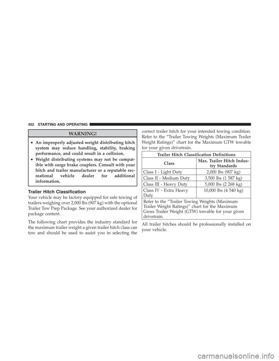
Trailer Hitch Classification
Your vehicle may be factory equipped for safe towing of
trailers weighing over 2,000 lbs (907 kg) with the optional
Trailer Tow Prep Package. See your authorized dealer for
package content.
The following chart provides the industry standard for
the maximum trailer weight a given trailer hitch class can
tow and should be used to assist you in selecting thecorrect trailer hitch for your intended towing condition.
Refer to the “Trailer Towing Weights (Maximum Trailer
Weight Ratings)” chart for the Maximum GTW towable
for your given drivetrain.
Trailer Hitch Classification Definitions
Class Max. Trailer Hitch Indus-
try Standards
Class I - Light Duty 2,000 lbs (907 kg)
Class II - Medium Duty 3,500 lbs (1 587 kg)
Class III - Heavy Duty 5,000 lbs (2 268 kg)
Class IV - Extra Heavy
Duty 10,000 lbs (4 540 kg)
Refer to the “Trailer Towing Weights (Maximum
Trailer Weight Ratings)” chart for the Maximum
Gross Trailer Weight (GTW) towable for your given
drivetrain.
All trailer hitches should be professionally installed on
your vehicle.
452 STARTING AND OPERATING
Page 460 of 594
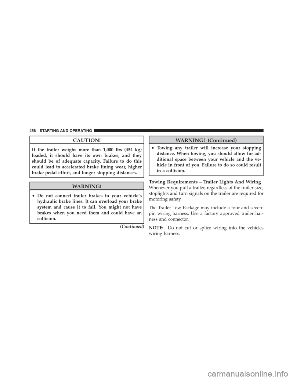
CAUTION!
If the trailer weighs more than 1,000 lbs (454 kg)
loaded, it should have its own brakes, and they
should be of adequate capacity. Failure to do this
could lead to accelerated brake lining wear, higher
brake pedal effort, and longer stopping distances.
WARNING!
•Do not connect trailer brakes to your vehicle’s
hydraulic brake lines. It can overload your brake
system and cause it to fail. You might not have
brakes when you need them and could have an
collision.(Continued)
WARNING! (Continued)
•Towing any trailer will increase your stopping
distance. When towing, you should allow for ad-
ditional space between your vehicle and the ve-
hicle in front of you. Failure to do so could result
in a collision.
Towing Requirements – Trailer Lights And Wiring
Whenever you pull a trailer, regardless of the trailer size,
stoplights and turn signals on the trailer are required for
motoring safety.
The Trailer Tow Package may include a four and seven-
pin wiring harness. Use a factory approved trailer har-
ness and connector.
NOTE:Do not cut or splice wiring into the vehicles
wiring harness.
458 STARTING AND OPERATING
Page 475 of 594

NOTE:
•For vehicles so equipped, do not attempt to install a
center cap or wheel cover on the compact spare.
•Refer to “Compact Spare Tire” and to “Limited-Use
Spare” under “Tires—General Information” in “Start-
ing and Operating” for additional warnings, cautions,
and information about the spare tire, its use, and
operation.
8. Install the lug nuts with the cone shaped end of the lug
nut toward the wheel. Lightly tighten the lug nuts.
WARNING!
To avoid the risk of forcing the vehicle off the jack,
do not tighten the wheel nuts fully until the vehicle
has been lowered. Failure to follow this warning may
result in personal injury. 9. Lower the vehicle to the ground by turning the jack
handle counterclockwise.
10. Finish tightening the lug nuts. Push down on the
wrench while at the end of the handle for increased
leverage. Tighten the lug nuts in a star pattern until each
nut has been tightened twice. The correct tightness of
each lug nut is 110 ft/lb. (150 N·m). If in doubt about the
correct tightness, have them checked with a torque
wrench by your authorized dealer or at a service station.
11. Stow the jack, tools and flat tire. Make sure the base
of the jack faces the front of the vehicle before tightening
down the fastener.
6
WHAT TO DO IN EMERGENCIES 473
Page 476 of 594

WARNING!
•A loose tire or jack thrown forward in a collision
or hard stop could endanger the occupants of the
vehicle. Always stow the jack parts and the spare
tire in the places provided.
•Have the deflated (flat) tire repaired or replaced
immediately.
Road Tire Installation
1. Mount the road tire on the axle.
2. Install the remaining lug nuts with the cone shaped
end of the nut toward the wheel. Lightly tighten the lug
nuts.
WARNING!
To avoid the risk of forcing the vehicle off the jack,
do not tighten the wheel nuts fully until the vehicle
has been lowered. Failure to follow this warning may
result in personal injury.
3. Lower the vehicle to the ground by turning the jack
handle counterclockwise.
4. Finish tightening the lug nuts. Push down on the
wrench while at the end of the handle for increased
leverage. Tighten the lug nuts in a star pattern until each
nut has been tightened twice. The correct tightness of
each lug nut is 110 ft/lbs (150 N·m). If in doubt about the
correct tightness, have them checked with a torque
wrench by your authorized dealer or service station.
474 WHAT TO DO IN EMERGENCIES
Page 516 of 594
•Do not change the thermostat for Summer or Winter
operation. If replacement is ever necessary, install
ONLY the correct type thermostat. Other designs may
result in unsatisfactory coolant performance, poor gas
mileage, and increased emissions.
Brake System
In order to assure brake system performance, all brake
system components should be inspected periodically.
Refer to the “Maintenance Schedule” for the proper
maintenance intervals.
WARNING!
Riding the brakes can lead to brake failure and
possibly a collision. Driving with your foot resting or
riding on the brake pedal can result in abnormally
high brake temperatures, excessive lining wear, and
possible brake damage. You would not have your full
braking capacity in an emergency.
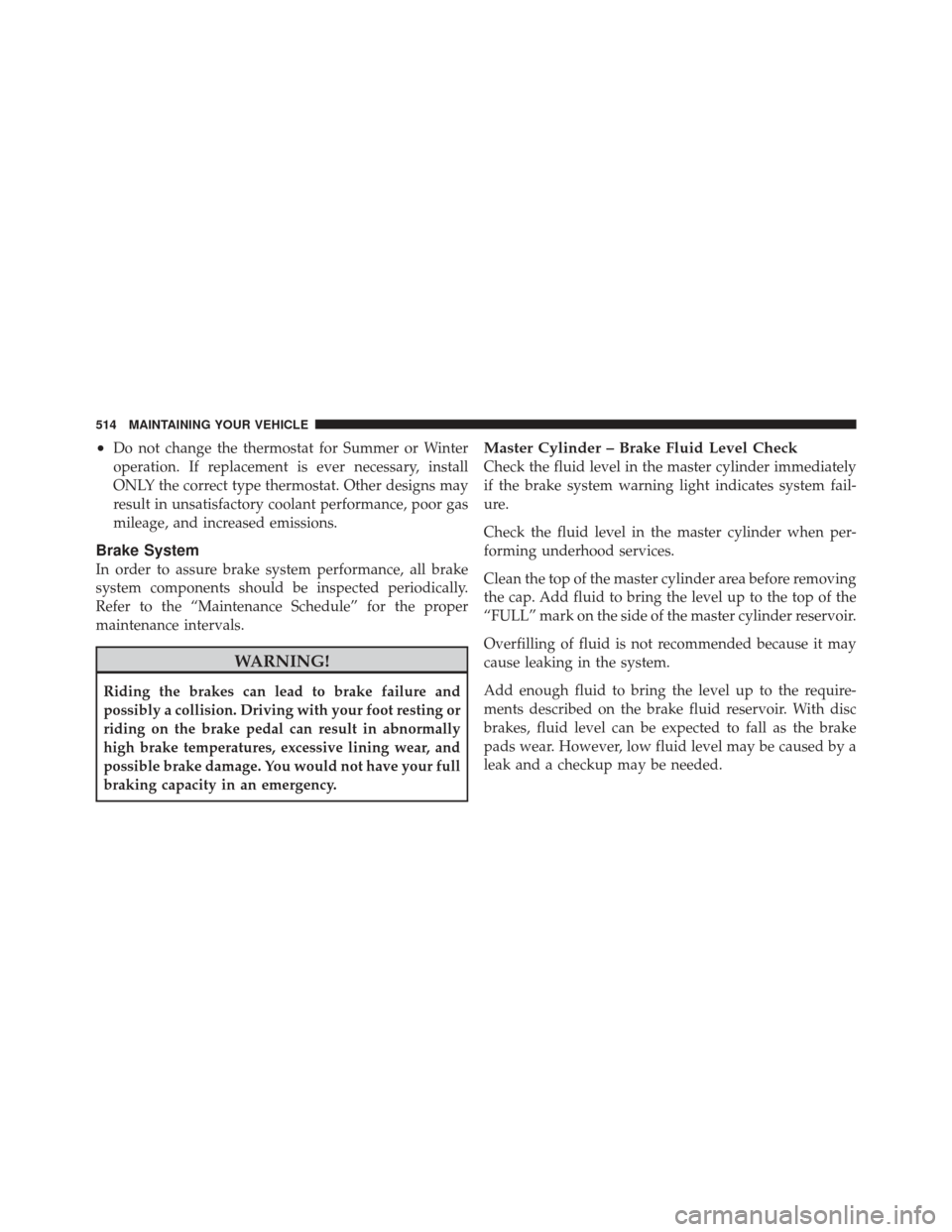
Master Cylinder – Brake Fluid Level Check
Check the fluid level in the master cylinder immediately
if the brake system warning light indicates system fail-
ure.
Check the fluid level in the master cylinder when per-
forming underhood services.
Clean the top of the master cylinder area before removing
the cap. Add fluid to bring the level up to the top of the
“FULL” mark on the side of the master cylinder reservoir.
Overfilling of fluid is not recommended because it may
cause leaking in the system.
Add enough fluid to bring the level up to the require-
ments described on the brake fluid reservoir. With disc
brakes, fluid level can be expected to fall as the brake
pads wear. However, low fluid level may be caused by a
leak and a checkup may be needed.
514 MAINTAINING YOUR VEHICLE
Page 537 of 594
CAUTION!
Do not touch the new bulb with your fingers. Oil
contamination will severely shorten bulb life. If the
bulb comes in contact with an oily surface, clean the
bulb with rubbing alcohol.
3. Disconnect the bulb from the socket assembly and
install the replacement bulb.
4. Reinstall the bulb and socket assembly into the head-
lamp assembly, and then turn it clockwise.
Front Low Beam Headlamp And Park/Turn Lamp
— Models With High Intensity Discharge
Headlamps (HID)
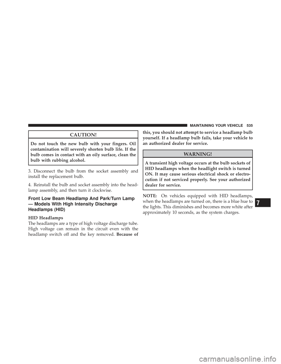
HID Headlamps
The headlamps are a type of high voltage discharge tube.
High voltage can remain in the circuit even with the
headlamp switch off and the key removed. Because ofthis, you should not attempt to service a headlamp bulb
yourself. If a headlamp bulb fails, take your vehicle to
an authorized dealer for service.
WARNING!
A transient high voltage occurs at the bulb sockets of
HID headlamps when the headlight switch is turned
ON. It may cause serious electrical shock or electro-
cution if not serviced properly. See your authorized
dealer for service.
NOTE: On vehicles equipped with HID headlamps,
when the headlamps are turned on, there is a blue hue to
the lights. This diminishes and becomes more white after
approximately 10 seconds, as the system charges.
7
MAINTAINING YOUR VEHICLE 535
Page 566 of 594
We appreciate that you have made a major investment
when you purchased the vehicle. An authorized dealer
has also made a major investment in facilities, tools, and
training to assure that you are absolutely delighted with
the ownership experience. You’ll be pleased with their
sincere efforts to resolve any warranty issues or related
concerns.
WARNING!
Engine exhaust, some of its constituents, and certain
vehicle components contain, or emit, chemicals
known to the State of California to cause cancer and
birth defects, or other reproductive harm. In addi-
tion, certain fluids contained in vehicles and certain
products of component wear contain, or emit, chemi-
cals known to the State of California to cause cancer
and birth defects, or other reproductive harm.
WARRANTY INFORMATION
See the Warranty Information Booklet, located on the
DVD, for the terms and provisions of Chrysler Group
LLC warranties applicable to this vehicle and market.
MOPAR�PARTS
MOPAR� fluids, lubricants, parts, and accessories are
available from an authorized dealer. They are recom-
mended for your vehicle in order to help keep the vehicle
operating at its best.
REPORTING SAFETY DEFECTS
In the 50 United States and Washington, D.C.
If you believe that your vehicle has a defect that could
cause a crash or cause injury or death, you should
immediately inform the National Highway Traffic Safety
Administration (NHTSA) in addition to notifying the
manufacturer.
564 IF YOU NEED CONSUMER ASSISTANCE