2012 CHRYSLER TOWN AND COUNTRY battery
[x] Cancel search: batteryPage 10 of 132

KEY FOB
Locking And Unlocking The
Doors/Liftgate
• Press the LOCK button once to lock allthe doors and the liftgate. Press the
UNLOCK button once to unlock the
driver’s door only and twice within five
seconds to unlock all the doors and
liftgate.
• All doors can be programmed to unlock on the first press of the UNLOCK button. Refer to Programmable Features in this guide.
Panic Alarm
• Press the PANIC button once to turn the panic alarm on.
• Wait approximately three seconds and press the button a second time to turn the panicalarm off.
Power Liftgate
• Press the LIFTGATE button twice within five seconds to power open/close the PowerLiftgate. If the button is pressed twice again while the liftgate is being power closed, the
liftgate will reverse to the full open position.
Power Sliding Doors
• Press the LEFT or RIGHT Power Sliding Door button twice within five seconds to poweropen/close the Power Sliding Door. If the button is pressed twice again while the door is
being power closed, the door will reverse to the full open position.
Emergency Key
• Should the battery in the vehicle or the Key Fob transmitter go dead, there is anemergency key located in the Key Fob that can be used for locking and unlocking the
doors. To remove the emergency key, slide the button at the top of the Key Fob sideways
with your thumb and then pull the key out with your other hand.
• The emergency key is used to unlock/lock the driver's door and the glove compartment.
GETTING STARTED
08
Page 11 of 132

• In case the Key Fob battery is dead, usethe emergency key to open the door. If
the vehicle is equipped with Keyless
Enter-N-Go™, remove the ENGINE
START/STOP button by inserting the
metal part of the emergency key under
the chrome bezel at the 6 o’clock position
and gently pry the button loose.
NOTE:The ENGINE START/STOP button
should only be removed or inserted with the
ignition in the LOCK position (OFF position
for Keyless Enter-N-Go™).
• With the ENGINE START/STOP buttonremoved, start the vehicle by inserting the
Key Fob in the ignition and turning to the
Start position.
CAUTION!
• If your vehicle battery becomes low or dead, your Key Fob will become locked in theignition.
• Do not attempt to remove the Key Fob while in this condition, damage could occur to the Key Fob or ignition module. Only remove the emergency key for locking and
unlocking the doors.
• Leave the Key Fob in the ignition and either: • Jump Start the vehicle.
• Charge the battery.
• Contact your dealer for assistance on how to remove the Key Fob using the manualover ride method.
GETTING STARTED
09
Page 73 of 132

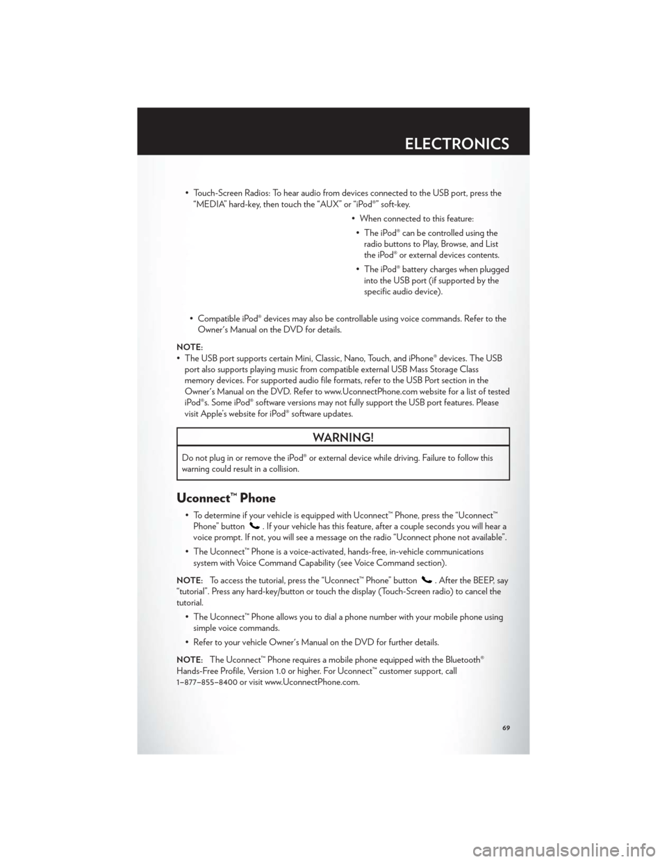
• Touch-Screen Radios: To hear audio from devices connected to the USB port, press the“MEDIA” hard-key, then touch the “AUX” or “iPod®” soft-key.
• When connected to this feature:• The iPod® can be controlled using the radio buttons to Play, Browse, and List
the iPod® or external devices contents.
• The iPod® battery charges when plugged into the USB port (if supported by the
specific audio device).
• Compatible iPod® devices may also be controllable using voice commands. Refer to the Owner's Manual on the DVD for details.
NOTE:
• The USB port supports certain Mini, Classic, Nano, Touch, and iPhone® devices. The USBport also supports playing music from compatible external USB Mass Storage Class
memory devices. For supported audio file formats, refer to the USB Port section in the
Owner's Manual on the DVD. Refer to www.UconnectPhone.com website for a list of tested
iPod®s. Some iPod® software versions may not fully support the USB port features. Please
visit Apple’s website for iPod® software updates.
WARNING!
Do not plug in or remove the iPod® or external device while driving. Failure to follow this
warning could result in a collision.
Uconnect™ Phone
• To determine if your vehicle is equipped with Uconnect™ Phone, press the “Uconnect™Phone” button
. If your vehicle has this feature, after a couple seconds you will hear a
voice prompt. If not, you will see a message on the radio “Uconnect phone not available”.
• The Uconnect™ Phone is a voice-activated, hands-free, in-vehicle communications system with Voice Command Capability (see Voice Command section).
NOTE:To access the tutorial, press the “Uconnect™ Phone” button. After the BEEP, say
“tutorial”. Press any hard-key/button or touch the display (Touch-Screen radio) to cancel the
tutorial.
• The Uconnect™ Phone allows you to dial a phone number with your mobile phone usingsimple voice commands.
• Refer to your vehicle Owner's Manual on the DVD for further details.
NOTE:The Uconnect™ Phone requires a mobile phone equipped with the Bluetooth®
Hands-Free Profile, Version 1.0 or higher. For Uconnect™ customer support, call
1–877–855–8400 or visit www.UconnectPhone.com.
ELECTRONICS
69
Page 82 of 132

Sound Horn With Lock
• To turn the horn chirp on or off when the doors are locked:• Press the LOCK button for at least 4 seconds, but no longer than 10 seconds. Then, press the PANIC button while still holding the LOCK button.
• Release both buttons at the same time.
Flashing Lights With Lock
• The turn signal lights flashing, when the doors are locked or unlocked, feature can be turned on or off. To turn this feature on or off:
• Press and hold the UNLOCK button for at least 4 seconds, but no longer than 10 seconds. Then, press and hold the LOCK button while still holding the UNLOCK
button.
• Release both buttons at the same time.
UNIVERSAL GARAGE DOOR OPENER (HomeLink®)
• HomeLink® replaces up to three hand-held transmitters that operate devices such as garage door openers, motorized gates, lighting or home security systems. The
HomeLink® unit is powered by your vehicles 12 Volt battery.
• The HomeLink® buttons that are located in the overhead console or sunvisor designate the three different HomeLink® channels.
• The HomeLink® indicator is located above the center button.
Before You Begin Programming
HomeLink®
• Be sure that your vehicle is parked outside of the garage before you begin
programming.
• For more efficient programming and accurate transmission of the
radio-frequency signal it is recommended
that a new battery be placed in the
hand-held transmitter of the device that is
being programmed to the HomeLink®
system.
• Erase all channels before you begin programming. To erase the channels, place the ignition switch into the ON/RUN position, then press and hold the two outside
HomeLink® buttons (I and III) for up 20 seconds or until the red indicator flashes.
NOTE:
• Erasing all channels should only be performed when programming HomeLink® for the firsttime. Do not erase channels when programming additional buttons.
• If you have any problems, or require assistance, please call toll-free 1–800–355–3515 or, on the Internet at www.HomeLink.com for information or assistance.
ELECTRONICS
78
Page 85 of 132

WARNING!
To Avoid Serious Injury or Death: Do not use a three-prong adaptor. Do not insert any
objects into the receptacles. Do not touch with wet hands. Close the lid when not in use. If
this outlet is mishandled, it may cause an electric shock and failure.
POWER OUTLETS
• Two 12 Volt (13 Amp) power outlets arelocated on the lower instrument panel,
below the open storage bin. The
driver-side power outlet is controlled by
the ignition switch and the passenger-side
power outlet is connected directly to the
battery. The driver-side power outlet will
also operate a conventional cigar lighter
unit (if equipped with an optional
Smoker's Package).
• One outlet in the removable floor console (if equipped) shares a fuse with the lower outlet in the instrument panel and is also connected to the battery. Do not exceed a
maximum power of 160 Watts (13 Amps) shared between the lower panel outlet and the
removable floor console outlet.
• On vehicles equipped with the Super Console the power outlets are located under the retractable cover. To access the power outlets push down on the cover and slide it toward
the instrument panel.
• The outlet in the rear quarter panel near the liftgate and the upper outlet in the instrument panel are both controlled by the ignition switch. Each of these outlets can
support 160 Watts (13 Amps). Do not exceed 160 Watts (13 Amps) for each of these
outlets.
ELECTRONICS
81
Page 105 of 132

JUMP-STARTING
• If your vehicle has a discharged battery itcan be jump-started using a set of jumper
cables and a battery in another vehicle or
by using a portable battery booster pack.
• Jump-starting can be dangerous if done improperly so please follow the
procedures in this section carefully.
NOTE:When using a portable battery
booster pack follow the manufacturer’s
operating instructions and precautions.
Preparations for Jump-Start
• The battery in your vehicle is located on the left side of the engine compartment.
• Set the parking brake, shift the automatic transmission into PARK and turn the ignition to LOCK.
• Turn off the heater, radio, and all unnecessary electrical accessories.
• If using another vehicle to jump-start the battery, park the vehicle within the jumper cables reach, set the parking brake and make sure the ignition is OFF.
Jump-Starting Procedure
• Connect the positive (+)end of the jumper cable to the positive (+)post of the discharged
vehicle.
• Connect the opposite end of the positive (+)jumper cable to the positive(+)post of the
booster battery.
• Connect the negative end (-)of the jumper cable to the negative (-)post of the booster
battery.
• Connect the opposite end of the negative (-)jumper cable to a good engine ground
(exposed metal part of the discharged vehicle's engine) away from the battery and fuel
injection system.
• Start the engine in the vehicle that has the booster battery, let the engine idle a few minutes, and then start the engine in the vehicle with the discharged battery.
Once the engine is started, remove the jumper cables in the reverse sequence:
• Disconnect the negative (-)
jumper cable from the negative (-)post of the vehicle with the
discharged battery.
• Disconnect the negative end (-)of the jumper cable from the negative (-)post of the
booster battery.
• Disconnect the opposite end of the positive (+)jumper cable from the positive(+)post of
the booster battery.
WHAT TO DO IN EMERGENCIES
101
Page 106 of 132

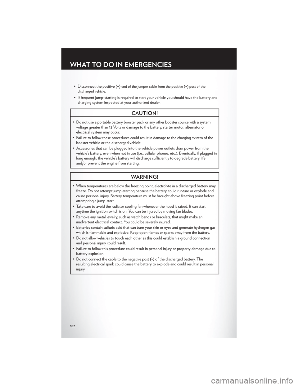
• Disconnect the positive(+)end of the jumper cable from the positive (+)post of the
discharged vehicle.
• If frequent jump-starting is required to start your vehicle you should have the battery and charging system inspected at your authorized dealer.
CAUTION!
• Do not use a portable battery booster pack or any other booster source with a systemvoltage greater than 12 Volts or damage to the battery, starter motor, alternator or
electrical system may occur.
• Failure to follow these procedures could result in damage to the charging system of the booster vehicle or the discharged vehicle.
• Accessories that can be plugged into the vehicle power outlets draw power from the vehicle’s battery, even when not in use (i.e., cellular phones, etc.). Eventually, if plugged in
long enough, the vehicle’s battery will discharge sufficiently to degrade battery life
and/or prevent the engine from starting.
WARNING!
• When temperatures are below the freezing point, electrolyte in a discharged battery mayfreeze. Do not attempt jump-starting because the battery could rupture or explode and
cause personal injury. Battery temperature must be brought above freezing point before
attempting a jump-start.
• Take care to avoid the radiator cooling fan whenever the hood is raised. It can start anytime the ignition switch is on. You can be injured by moving fan blades.
• Remove any metal jewelry, such as watch bands or bracelets, that might make an inadvertent electrical contact. You could be severely injured.
• Batteries contain sulfuric acid that can burn your skin or eyes and generate hydrogen gas which is flammable and explosive. Keep open flames or sparks away from the battery.
• Do not allow vehicles to touch each other as this could establish a ground connection and personal injury could result.
• Failure to follow this procedure could result in personal injury or property damage due to battery explosion.
• Do not connect the cable to the negative post (-)of the discharged battery. The
resulting electrical spark could cause the battery to explode and could result in personal
injury.
WHAT TO DO IN EMERGENCIES
102
Page 118 of 132

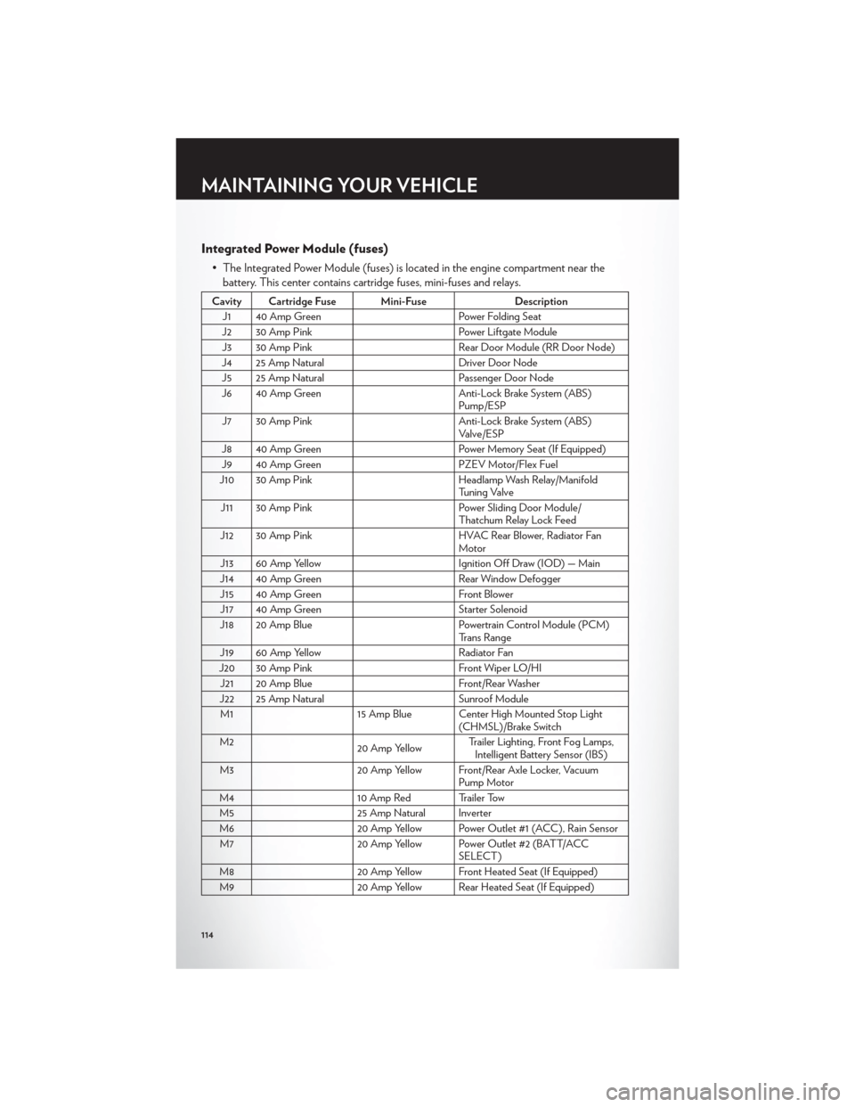
Integrated Power Module (fuses)
• The Integrated Power Module (fuses) is located in the engine compartment near thebattery. This center contains cartridge fuses, mini-fuses and relays.
Cavity Cartridge Fuse Mini-Fuse Description
J1 40 Amp Green Power Folding Seat
J2 30 Amp Pink Power Liftgate Module
J3 30 Amp Pink Rear Door Module (RR Door Node)
J4 25 Amp Natural Driver Door Node
J5 25 Amp Natural Passenger Door Node
J6 40 Amp Green Anti-Lock Brake System (ABS)
Pump/ESP
J7 30 Amp Pink Anti-Lock Brake System (ABS)
Valve/ESP
J8 40 Amp Green Power Memory Seat (If Equipped)
J9 40 Amp Green PZEV Motor/Flex Fuel
J10 30 Amp Pink Headlamp Wash Relay/Manifold
Tuning Valve
J11 30 Amp Pink Power Sliding Door Module/
Thatchum Relay Lock Feed
J12 30 Amp Pink HVAC Rear Blower, Radiator Fan
Motor
J13 60 Amp Yellow Ignition Off Draw (IOD) — Main
J14 40 Amp Green Rear Window Defogger
J15 40 Amp Green Front Blower
J17 40 Amp Green Starter Solenoid
J18 20 Amp Blue Powertrain Control Module (PCM)
Trans Range
J19 60 Amp Yellow Radiator Fan
J20 30 Amp Pink Front Wiper LO/HI
J21 20 Amp Blue Front/Rear Washer
J22 25 Amp Natural Sunroof Module
M1 15 Amp Blue Center High Mounted Stop Light
(CHMSL)/Brake Switch
M2 20 Amp YellowTrailer Lighting, Front Fog Lamps,
Intelligent Battery Sensor (IBS)
M3 20 Amp Yellow Front/Rear Axle Locker, Vacuum
Pump Motor
M4 10 Amp Red Trailer Tow
M5 25 Amp Natural Inverter
M6 20 Amp Yellow Power Outlet #1 (ACC), Rain Sensor
M7 20 Amp Yellow Power Outlet #2 (BATT/ACC
SELECT)
M8 20 Amp Yellow Front Heated Seat (If Equipped)
M9 20 Amp Yellow Rear Heated Seat (If Equipped)
MAINTAINING YOUR VEHICLE
114