Page 81 of 132

• The EVIC can be used to program the following Personal Settings. Press and release theMENU button until Personal Settings display")
PROGRAMMABLE FEATURES
Electronic Vehicle Information Center (EVIC)
• The EVIC can be used to program the following Personal Settings. Press and release theMENU button until Personal Settings displays, then press the DOWN button
to
scroll through the settings. Press the SELECT button
to change the setting.
• Language • Intermittent Wiper Option
• Nav-Turn By Turn • Rain Sensing Wipers
• Enable/Disable the Rear Park Assist System • Key-Off Power Delay
• Auto Unlock Doors • Illuminated Approach
• Remote Unlock Sequence • Flashers with Sliding Door
• RKE Linked To Memory • Hill Start Assist (HSA)
• Remote Start Comfort Sys. • Keyless Enter-N-Go™ (Passive Entry)
• Horn With Remote Lock • Easy Exit Seat
• Horn With Remote Start • Tilt Mirror In Reverse
• Flash Lamps With Lock • Blind Spot Alert
• Automatic High Beams • Calibrate Compass
• Headlamp Off Delay • Compass Variance
• Headlamps with Wipers (Available with Auto Headlights Only) • Turn Menu Off
Key Fob Programmable Features
• The following features may also be programmed by using the Key Fob transmitter or the
ignition switch and driver's door lock switch.
NOTE:Pressing the LOCK button while you are inside the vehicle will activate the Vehicle
Security Alarm. Opening a door with the Vehicle Security Alarm activated will cause the alarm
to sound. Press the UNLOCK button to deactivate the Vehicle Security Alarm.
Unlock On First Press
• To unlock either the driver's side, or all doors, on the first press of the UNLOCK button:
• Press and hold the LOCK button for at least 4 seconds, but no longer than 10 seconds. Then, press and hold the UNLOCK button while still holding the LOCK button.
• Release both buttons at the same time.
Auto Unlock Doors On Exit
• To have all of the vehicle doors unlock when any door is opened: • Enter your vehicle and close all the doors.
• Cycle the ignition switch between LOCK and ON and then back to LOCK four times, ending up in the LOCK position (do not start the engine).
• Press the power door UNLOCK switch to unlock the doors. A single chime will indicate that programming is complete.
ELECTRONICS
77
Page 82 of 132

Sound Horn With Lock
• To turn the horn chirp on or off when the doors are locked:• Press the LOCK button for at least 4 seconds, but no longer than 10 seconds. Then, press the PANIC button while still holding the LOCK button.
• Release both buttons at the same time.
Flashing Lights With Lock
• The turn signal lights flashing, when the doors are locked or unlocked, feature can be turned on or off. To turn this feature on or off:
• Press and hold the UNLOCK button for at least 4 seconds, but no longer than 10 seconds. Then, press and hold the LOCK button while still holding the UNLOCK
button.
• Release both buttons at the same time.
UNIVERSAL GARAGE DOOR OPENER (HomeLink®)
• HomeLink® replaces up to three hand-held transmitters that operate devices such as garage door openers, motorized gates, lighting or home security systems. The
HomeLink® unit is powered by your vehicles 12 Volt battery.
• The HomeLink® buttons that are located in the overhead console or sunvisor designate the three different HomeLink® channels.
• The HomeLink® indicator is located above the center button.
Before You Begin Programming
HomeLink®
• Be sure that your vehicle is parked outside of the garage before you begin
programming.
• For more efficient programming and accurate transmission of the
radio-frequency signal it is recommended
that a new battery be placed in the
hand-held transmitter of the device that is
being programmed to the HomeLink®
system.
• Erase all channels before you begin programming. To erase the channels, place the ignition switch into the ON/RUN position, then press and hold the two outside
HomeLink® buttons (I and III) for up 20 seconds or until the red indicator flashes.
NOTE:
• Erasing all channels should only be performed when programming HomeLink® for the firsttime. Do not erase channels when programming additional buttons.
• If you have any problems, or require assistance, please call toll-free 1–800–355–3515 or, on the Internet at www.HomeLink.com for information or assistance.
ELECTRONICS
78
Page 83 of 132

Programming A Rolling Code
• For programming Garage Door Openers that were manufactured after 1995. TheseGarage Door Openers can be identified by the “LEARN” or “TRAIN” button located
where the hanging antenna is attached to the Garage Door Opener. It is NOT the button
that is normally used to open and close the door. The name and color of the button may
vary by manufacturer.
• Place the ignition switch into the ON/RUN position.
• Place the hand-held transmitter 1 to 3 in (3 to 8 cm) away from the HomeLink® button you wish to program while keeping the HomeLink® indicator light in view.
• Simultaneously press and hold both the HomeLink® button you want to program and the hand-held transmitter button.
• Continue to hold both buttons and observe the indicator light. The Homelink® indicator will flash slowly and then rapidly after Homelink® has received the frequency signal from
the hand-held transmitter. Release both buttons after the indicator light changes from
slow to rapid.
• At the garage door opener motor (in the garage), locate the “LEARN” or “TRAINING” button. This can usually be found where the hanging antenna wire is attached to the
garage door opener motor. Firmly press and release the “LEARN” or “TRAINING”
button.
NOTE:You have 30 seconds in which to initiate the next step after the LEARN button has
been pressed.
• Return to the vehicle and press the programmed HomeLink® button twice (holding thebutton for two seconds each time). If the device is plugged in and activates, programming
is complete.
NOTE:If the device does not activate, press the button a third time (for two seconds) to
complete the training.
• To program the remaining two HomeLink® buttons, repeat each step for each remainingbutton. DO NOT erase the channels.
Programming A Non-Rolling Code
• For programming Garage Door Openers manufactured before 1995.
• Turn the ignition switch to the ON/RUN position.
• Place the hand-held transmitter 1 to 3 in (3 to 8 cm) away from the HomeLink® buttonyou wish to program while keeping the HomeLink® indicator light in view.
• Simultaneously press and hold both the HomeLink® button you want to program and the hand-held transmitter button.
• Continue to hold both buttons and observe the indicator light. The Homelink® indicator will flash slowly and then rapidly after Homelink® has received the frequency signal from
the hand-held transmitter. Release both buttons after the indicator light changes from
slow to rapid.
• Press and hold the programmed HomeLink® button and observe the indicator light.
ELECTRONICS
79
Page 84 of 132
 should activate when the HomeLink® button is pressed.
• To program the two remaining Hom")
NOTE:
• If the indicator light stays on constantly, programming is complete and the garage door (ordevice) should activate when the HomeLink® button is pressed.
• To program the two remaining HomeLink® buttons, repeat each step for each remaining button. DO NOT erase the channels.
Using HomeLink®
• To operate, press and release the programmed HomeLink® button. Activation will nowoccur for the programmed device (i.e., garage door opener, gate operator, security
system, entry door lock, home/office lighting, etc.,). The hand-held transmitter of the
device may also be used at any time.
WARNING!
• Your motorized door or gate will open and close while you are programming the universaltransceiver. Do not program the transceiver if people or pets are in the path of the door
or gate.
• Do not run your vehicle in a closed garage or confined area while programming the transceiver. Exhaust gas from your vehicle contains Carbon Monoxide (CO) which is
odorless and colorless. Carbon Monoxide is poisonous when inhaled and can cause you
and others to be severely injured or killed.
POWER INVERTER
• There is a 115 Volt, 150 Watt powerinverter outlet located on the left rear trim
panel immediately behind the second row
left passenger seat. This outlet can power
cellular phones, electronics and other low
power devices requiring power up to 150
Watts.
• Press the switch located in the center of the instrument panel to turn the power to
the outlet on.
• Press the switch again to turn the power off.
• The status indicator of the AC power inverter indicates whether the inverter is producing AC power.
NOTE:The power inverter is designed with built-in overload protection. If the power rating
of 150 Watts is exceeded, the power inverter will automatically shut down. Once the electrical
device has been removed from the outlet, the inverter should automatically reset. If the power
rating exceeds approximately 170 Watts, the power inverter may have to be reset manually. To
reset the inverter manually, unplug the device and plug it in again. To avoid overloading the
circuit, check the power ratings on electrical devices prior to using the inverter.
ELECTRONICS
80
Page 85 of 132

WARNING!
To Avoid Serious Injury or Death: Do not use a three-prong adaptor. Do not insert any
objects into the receptacles. Do not touch with wet hands. Close the lid when not in use. If
this outlet is mishandled, it may cause an electric shock and failure.
POWER OUTLETS
• Two 12 Volt (13 Amp) power outlets arelocated on the lower instrument panel,
below the open storage bin. The
driver-side power outlet is controlled by
the ignition switch and the passenger-side
power outlet is connected directly to the
battery. The driver-side power outlet will
also operate a conventional cigar lighter
unit (if equipped with an optional
Smoker's Package).
• One outlet in the removable floor console (if equipped) shares a fuse with the lower outlet in the instrument panel and is also connected to the battery. Do not exceed a
maximum power of 160 Watts (13 Amps) shared between the lower panel outlet and the
removable floor console outlet.
• On vehicles equipped with the Super Console the power outlets are located under the retractable cover. To access the power outlets push down on the cover and slide it toward
the instrument panel.
• The outlet in the rear quarter panel near the liftgate and the upper outlet in the instrument panel are both controlled by the ignition switch. Each of these outlets can
support 160 Watts (13 Amps). Do not exceed 160 Watts (13 Amps) for each of these
outlets.
ELECTRONICS
81
Page 86 of 132
NOTE:
• Do not exceed the maximum power of 160 Watts (13 Amps) at 12 Volts. If the 160 Watt(13 Amp) power rating is exceeded, the fuse protecting the system will need to be replaced.
• Power outlets are designed for accessory plugs only. Do not insert any other object in the power outlet as this will damage the outlet and blow the fuse. Improper use of the power
outlet can cause damage not covered by your new vehicle warranty.
ELECTRONICS
82
Page 87 of 132

IN-FLOOR STORAGE – STOW 'N GO®
Second Row Seat Storage Bins
• Storage bins are located in the floor in front of the second row seats that can be usedwhen the second row seat is in the upright position. Pull up on the storage bin latch to
open the cover. Slide the storage bin locking mechanism to the "Lock" position to allow
greater access to the storage bin.
Cargo Area Storage
• The liftgate sill plate has a raised line with the statement “Load To This Line”. This lineindicates how far rearward cargo can be placed without interfering with liftgate closing.
WARNING!
In a collision, serious injury could result if the seat storage bin covers are not properly
latched. Do not drive the vehicle with the storage bin covers open. Keep the storage bin
covers closed and latched while the vehicle is in motion. Do not use a storage bin latch as a
tie down.
ROOF LUGGAGE RACK
• The crossbars on your vehicle aredelivered stowed within the roof rack side
rails. When installed, the roof rack can
hold a maximum of 150 lbs (68 kg) of
evenly distributed weight.
Installing The Crossbars
• To install the crossbars, completely loosenthe thumb screws at both ends and lift the
crossbar from its stowed position.
• Bend the pivot points at each end of the crossbar and slide the thumb screw down.
• Set the crossbars into position and tighten the thumb screws.
NOTE:Make sure the directional arrow on the crossbar aligns with the directional arrow on
the side rail.
• Refer to the Owner's Manual on the DVD for further details.
UTILITY
83
Page 88 of 132
TRAILER TOWING WEIGHTS (MAXIMUM TRAILER WEIGHT RATINGS)
Engine/TransmissionGCWR (Gross Combined
Wt. Rating) Frontal AreaMax. GTW (Gross Trailer
Wt.) Max. Tongue Wt.
3.6L/Automatic 8,750 lbs (3 969 kg) 40 sq ft (3.72 sq m)
Up to 2 persons & Luggage
3,600 lbs (1 633 kg)* 360 lbs (163 kg)
8,750 lbs (3 969 kg) 40 sq ft (3.72 sq m) 3 to 5 persons & Luggage
3,350 lbs (1 519 kg)* 335 lbs (152 kg)
8,750 lbs (3 969 kg) 40 sq ft (3.72 sq m) 6 to 7 persons & Luggage
3,000 lbs (1 360 kg)* 300 lbs (136 kg)
* For vehicles equipped with Fold-in-Floor seating, the Gross Trailer Weight must be reduced by 100 lbs (45 kg). Refer to local laws for maximum trailer
towing speeds.
NOTE: The trailer tongue weight must be considered as part of the combined weight of occupants and cargo, and should never exceed the weight
referenced on the Tire and Loading Information placard.
UTILITY
84
 1
1 2
2 3
3 4
4 5
5 6
6 7
7 8
8 9
9 10
10 11
11 12
12 13
13 14
14 15
15 16
16 17
17 18
18 19
19 20
20 21
21 22
22 23
23 24
24 25
25 26
26 27
27 28
28 29
29 30
30 31
31 32
32 33
33 34
34 35
35 36
36 37
37 38
38 39
39 40
40 41
41 42
42 43
43 44
44 45
45 46
46 47
47 48
48 49
49 50
50 51
51 52
52 53
53 54
54 55
55 56
56 57
57 58
58 59
59 60
60 61
61 62
62 63
63 64
64 65
65 66
66 67
67 68
68 69
69 70
70 71
71 72
72 73
73 74
74 75
75 76
76 77
77 78
78 79
79 80
80 81
81 82
82 83
83 84
84 85
85 86
86 87
87 88
88 89
89 90
90 91
91 92
92 93
93 94
94 95
95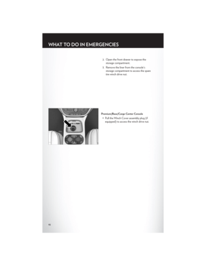 96
96 97
97 98
98 99
99 100
100 101
101 102
102 103
103 104
104 105
105 106
106 107
107 108
108 109
109 110
110 111
111 112
112 113
113 114
114 115
115 116
116 117
117 118
118 119
119 120
120 121
121 122
122 123
123 124
124 125
125 126
126 127
127 128
128 129
129 130
130 131
131 at 12 Volts. If the 160 Watt(13 Amp) power rating is exceeded, the fuse protecting the system will need to be replaced.
• Power outle")

Engine/TransmissionGCWR (Gross Combined
Wt. Rating) Frontal AreaMax. GTW (Gross Trailer
Wt.) Max. Tongue Wt.
3.6L/Automatic 8,750 lbs (3 969 kg)")