Page 413 of 652
To provide you with maximum comfort in the automatic
mode, during cold start-ups, the blower fan will remain
on low until the engine warms up. The fan will engage
immediately if the Defrost mode is selected, or by chang-
ing the front blower knob setting
Manual Operation
This system offers a full complement of manual override
features. The AUTO symbol in the front ATC display will
be turned off when the system is being used in the
manual mode.
NOTE:Each of these features operate independently
from each other. If any one feature is controlled manually,
the temperature doors will continue to operate automati-
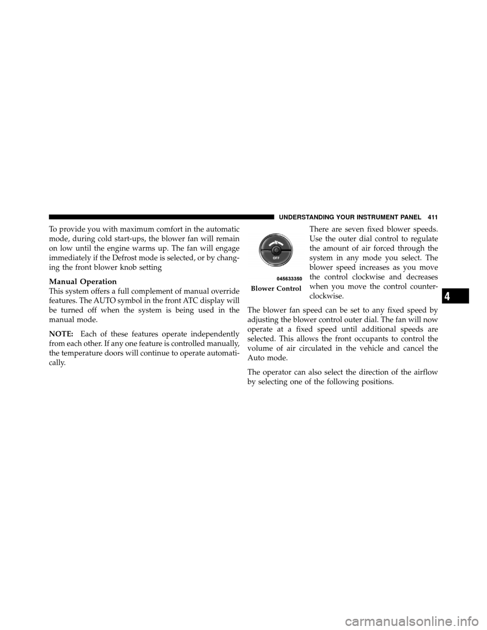
cally. There are seven fixed blower speeds.
Use the outer dial control to regulate
the amount of air forced through the
system in any mode you select. The
blower speed increases as you move
the control clockwise and decreases
when you move the control counter-
clockwise.
The blower fan speed can be set to any fixed speed by
adjusting the blower control outer dial. The fan will now
operate at a fixed speed until additional speeds are
selected. This allows the front occupants to control the
volume of air circulated in the vehicle and cancel the
Auto mode.
The operator can also select the direction of the airflow
by selecting one of the following positions.Blower Control
4
UNDERSTANDING YOUR INSTRUMENT PANEL 411
Page 416 of 652
Rear Automatic Temperature Control (ATC) — If
Equipped
The rear ATC system has floor air outlets at the rear of the
right side sliding door, and overhead outlets at each
outboard rear seating position. The system provides
heated air through the floor outlets or cool, dehumidified
air through the headliner outlets.
The rear system temperature control is on the front ATC
panel located on the instrument panel.
Pressing the Rear Temperature Lock button on the front
ATC panel, illuminates a lock symbol in the rear display.
The rear temperature and air source are controlled from
the front ATC panel.
Rear second row occupants can only adjust the rear ATC
control when the Rear Temperature Lock button is turned
off.The rear ATC system is located in the headliner, near the
center of the vehicle.
Rear ATC Control Features
1 - Blower Speed
3 - Rear Mode
2 - Rear Temperature 4 - Rear Temperature Lock
414 UNDERSTANDING YOUR INSTRUMENT PANEL
Page 418 of 652
CAUTION!
Interior air enters the Rear Automatic Temperature
Control System through an intake grille, located in
the right side trim panel behind the third row seats.
The heater outlets are located in the right side trim
panel, just behind the sliding door. Do not block or
place objects directly in front of the inlet grille or
heater outlets. The electrical system could overload
causing damage to the blower motor.
Rear Temperature Control
To change the temperature in the rear of the vehicle,
rotate the temperature knob counterclockwise to lower
the temperature, and clockwise to increase the tempera-
ture. The rear temperature settings are displayed in the
front ATC panel.When rear controls are locked by the front system, the
Rear Temperature Lock symbol on the temperature knob
is illuminated and any rear overhead adjustments are
ignored.
Rear Mode Control
Auto Mode
The rear system automatically maintains the correct
mode and comfort level desired by the rear seat occu-
pants.
416 UNDERSTANDING YOUR INSTRUMENT PANEL
Page 570 of 652
CAUTION!
The A/C air filter is identified with an arrow to
indicate airflow direction through the filter. Failure
to properly install the filter will result in the need to
replace it more often.
7. Rotate the glove compartment door back into position.
Body Lubrication
Locks and all body pivot points, including such items as
seat tracks, door hinge pivot points and rollers, liftgate,
tailgate, sliding doors and hood hinges, should be lubri-
cated periodically with a lithium-based grease, such as
MOPAR� Spray White Lube or equivalent, to assure
quiet, easy operation and to protect against rust and
wear. Prior to the application of any lubricant, the parts
concerned should be wiped clean to remove dust and
grit; after lubricating excess oil and grease should be
removed. Particular attention should also be given to hood latching components to ensure proper function.
When performing other underhood services, the hood
latch, release mechanism and safety catch should be
cleaned and lubricated.
The external lock cylinders should be lubricated twice a
year, preferably in the Fall and Spring. Apply a small
amount of a high quality lubricant such as MOPAR�
Lock Cylinder Lubricant or equivalent directly into the
lock cylinder.Windshield Wiper Blades
Clean the rubber edges of the wiper blades and the
windshield periodically with a sponge or soft cloth and a
mild nonabrasive cleaner. This will remove accumula-
tions of salt or road film.
Operation of the wipers on dry glass for long periods
may cause deterioration of the wiper blades. Always use
washer fluid when using the wipers to remove salt or dirt
from a dry windshield.
568 MAINTAINING YOUR VEHICLE
Page 589 of 652
CAUTION!
•When installing the Totally Integrated Power
Module cover, it is important to ensure the cover is
properly positioned and fully latched. Failure to
do so may allow water to get into the Integrated
Power Module, and possibly result in a electrical
system failure.
•When replacing a blown fuse, it is important to
use only a fuse having the correct amperage rating.
The use of a fuse with a rating other than indicated
may result in a dangerous electrical system over-
load. If a properly rated fuse continues to blow, it
indicates a problem in the circuit that must be
corrected.
The numbers inside the TIPM cover correspond to the
following table.
Cavity Cartridge
Fuse Mini-
Fuse Description
J1 40 Amp Green — Power Folding Seat
J2 30 Amp Pink — Power Liftgate
Module
J3 30 Amp Pink — Rear Door Module
J4 25 Amp Natural — Driver Door Node
J5 25 Amp Natural — Passenger Door Node
J6 40 Amp Green — Antilock Brakes
Pump/Stability
Control System
J7 30 Amp Pink — Antilock Brakes
Valve/Stability
Control System
7
MAINTAINING YOUR VEHICLE 587
Page 592 of 652
CavityCartridge
Fuse Mini-
Fuse Description
M10 — 15 Amp BlueIgnition Off Draw —
Video System, Satel-
lite Radio, DVD,
Hands-Free Module,
Universal Garage
Door Opener, Vanity
Lamp, Streaming
Video Module – If
Equipped
M11 — 10 Amp RedClimate Control
System
M12 — 30 Amp GreenAmplifier/Radio
M13 — 20 Amp YellowInstrument Cluster,
SIREN, Clock Mod-
ule, Multi-Function
Control Switch – If
EquippedCavity
Cartridge
Fuse Mini-
Fuse Description
M14 — 20 Amp YellowTrailer Tow – If
Equipped
M15 — 20 Amp YellowRear View Mirror,
Instrument Cluster,
Multi-Function Con-
trol Switch, Tire Pres-
sure Monitor, Glow
Plug Module – If
Equipped
M16 — 10 Amp RedAirbag Module/
Occupant Classifica-
tion Module
M17 — 15 Amp BlueLeft Tail/License/
Park Lamp, Running
Lamps
M18 — 15 Amp BlueRight Tail/Park/Run
Lamp
590 MAINTAINING YOUR VEHICLE
Page 594 of 652
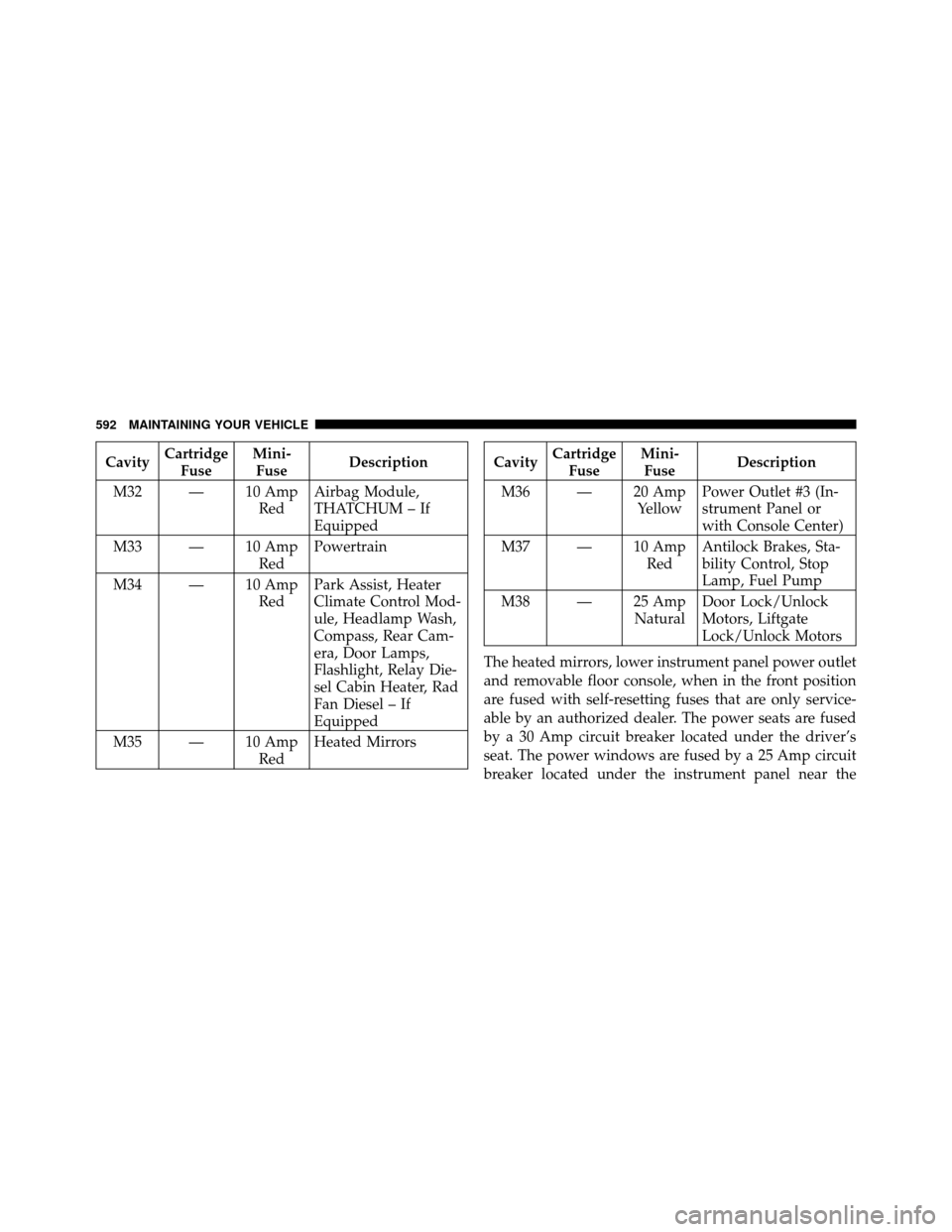
CavityCartridge
Fuse Mini-
Fuse Description
M32 — 10 Amp RedAirbag Module,
THATCHUM – If
Equipped
M33 — 10 Amp RedPowertrain
M34 — 10 Amp RedPark Assist, Heater
Climate Control Mod-
ule, Headlamp Wash,
Compass, Rear Cam-
era, Door Lamps,
Flashlight, Relay Die-
sel Cabin Heater, Rad
Fan Diesel – If
Equipped
M35 — 10 Amp RedHeated MirrorsCavity
Cartridge
Fuse Mini-
Fuse Description
M36 — 20 Amp YellowPower Outlet #3 (In-
strument Panel or
with Console Center)
M37 — 10 Amp RedAntilock Brakes, Sta-
bility Control, Stop
Lamp, Fuel Pump
M38 — 25 Amp NaturalDoor Lock/Unlock
Motors, Liftgate
Lock/Unlock Motors
The heated mirrors, lower instrument panel power outlet
and removable floor console, when in the front position
are fused with self-resetting fuses that are only service-
able by an authorized dealer. The power seats are fused
by a 30 Amp circuit breaker located under the driver’s
seat. The power windows are fused by a 25 Amp circuit
breaker located under the instrument panel near the
592 MAINTAINING YOUR VEHICLE
Page 598 of 652
Front Side Marker Lamp
1. Raise the hood to access the rear of the headlamp
housing.
NOTE:Access is somewhat limited. You may have to
remove the inner fender well or remove the headlamp
housing for bulb replacement.
2. Twist the socket and remove from the headlamp
housing, then pull the bulb out.
3. Push the new bulb into the socket and reinstall the
socket by twisting until locked into the headlamp
housing.
Fog Lamp
NOTE: Access to the fog lamp bulb is from the rear of
the fascia. On the left rear side of the fascia, remove the
push pin and lower the hinged access door on the air
dam.
1. From behind the bumper fascia, or the access panel on
the air dam, twist the bulb counterclockwise, and remove
bulb.
CAUTION!
Do not touch the new bulb with your fingers. Oil
contamination will severely shorten bulb life. If the
bulb comes in contact with an oily surface, clean the
bulb with rubbing alcohol.
2. Disconnect wire harness from the bulb.
596 MAINTAINING YOUR VEHICLE