Page 210 of 557
Adaptive Cruise Control (ACC) Operation
The speed control buttons (located on the right side of the
steering wheel) operates the ACC system.NOTE:
Any chassis/suspension modifications to the
vehicle will effect the performance of the Adaptive Cruise
Control.
Activating Adaptive Cruise Control (ACC)
You can only activate ACC if the vehicle speed is above
20 mph (32 km/h).
When the system is turned on and in the READY state,
the Electronic Vehicle Information Center (EVIC) dis-
plays “Adaptive Cruise Ready.”
When the system is OFF, the EVIC displays “Adaptive
Cruise Control Off.”
1 — DISTANCE SETTING
2 — RES +
3 — SET -
4 — CANCEL
5 — ON/OFF
6 — MODE
208 UNDERSTANDING THE FEATURES OF YOUR VEHICLE
Page 289 of 557
14. Sport ModeThis light will illuminate when Sport or Track
mode is selected. When Sport mode is selected,
the EVIC will display “Sport Mode Active
(Suspension)”.
This mode provides performance based tuning with
improved handling through an electronic controlled
damping system. This system reduces body roll and pitch
in many driving situations including cornering, accelera-
tion and braking.
When Track Mode is Selected, the EVIC will display
“Track Mode Activated (Suspension and Transmission)”.
In addition to SPORT suspension, Track mode also affects
transmission shifting in either Auto or Manual mode.
Refer to “AutoStick” in “Starting And Operating” for
further information. The transmission has a sportier,
more aggressive shift pattern. In Manual mode, the
transmission will hold gear at redline during manual
shifting (console shifter or paddle switches). 15. Vehicle Security Light — If Equipped
This light will flash at a fast rate for approxi-
mately 15 seconds, when the vehicle security
alarm is arming, and then will flash slowly
until the vehicle is disarmed.
16. Electronic Stability Control (ESC) OFF Indicator
Light — If Equipped This light indicates the Electronic Stability Con-
trol (ESC) is off.
17. Brake Warning Light This light monitors various brake functions,
including brake fluid level and parking brake
application. If the brake light turns on it may
indicate that the parking brake is applied, that
the brake fluid level is low, or that there is a problem with
the anti-lock brake system reservoir.
4
UNDERSTANDING YOUR INSTRUMENT PANEL 287
Page 367 of 557
•Automatic (Auto) Mode — This is the default position
when vehicle ignition is first turned on. This mode will
give a sporty, but comfortable ride. Within this mode,
the suspension will adapt to the vehicle inputs, includ-
ing vehicle speed, steering inputs, braking and accel-
eration.
•Sport Mode — This mode is driver selectable when the
vehicle is placed in SPORT mode (press the CON-
TROLS button and then the SPORT button on the
display screen). This mode will set suspension for
maximum performance handling and is intended for
spirited driving.
NOTE: The SPORT setting will provide a firmer ride. When SPORT mode is enabled, a flag will light up in the
instrument cluster. Refer to “Instrument Cluster Descrip-
tion” in “Understanding Your Instrument Panel” for
further information.
AUTO mode will provide a sporty comfortable ride,
where as SPORT or TRACK will be a firmer, sportier
suspension with better handling.
•Track Mode — This mode includes SPORT Suspension
and affects transmission shifting in either Auto or
Manual mode. Refer to “AutoStick” in “Starting And
Operating” for further information. In TRACK mode,
the transmission has a sportier, more aggressive shift
pattern. In Manual mode, the transmission will hold
gear at redline during manual shifting (console shifter
or paddle shifters).
5
STARTING AND OPERATING 365
Page 405 of 557
TIRE CHAINS
If driving conditions require tire chains for your vehicle,
use only chains that meet SAE type “Class S” specifica-
tions. In addition, only install tire chains on 245/45ZR20
size tires. Contact you local authorized dealership or tire
dealer for these size tires.
CAUTION!
To avoid damage to your vehicle or tires, observe the
following precautions:
•Because of restricted chain clearance between tires
and other suspension components, it is important
that only chains in good condition are used. Bro-
ken chains can cause serious damage. Stop the
vehicle immediately if noise occurs that could
indicate chain breakage. Remove the damaged
parts of the chain before further use.(Continued)
CAUTION! (Continued)
•Install chains on the rear wheels as tightly as
possible and then retighten after driving about
1�2mile (0.8 km).
•Do not exceed 30 mph (48 km/h).
•Drive cautiously and avoid severe turns and large
bumps, especially with a loaded vehicle.
•Use on rear wheels only.
•Do not drive for prolonged period on dry pave-
ment.
•Observe the tire chain manufacturer’s instructions
on the method of installation, operating speed,
and conditions for use. Always use the lower
suggested operating speed of the chain manufac-
turer if different from the speed recommended by
the manufacturer.
5
STARTING AND OPERATING 403
Page 426 of 557
Overloading
The load carrying components (axle, springs, tires,
wheels, etc.) of your vehicle will provide satisfactory
service as long as you do not exceed the GVWR and the
front and rear GAWR.
The best way to figure out the total weight of your
vehicle is to weigh it when it is fully loaded and ready for
operation. Weigh it on a commercial scale to ensure that
it is not over the GVWR.
Figure out the weight on the front and rear of the vehicle
separately. It is important that you distribute the load
evenly over the front and rear axles.
Overloading can cause potential safety hazards and
shorten useful service life. Heavier axles or suspension
components do not necessarily increase the vehicle’s
GVWR.
Loading
To load your vehicle properly, first figure out its empty
weight, axle-by-axle and side-by-side. Store heavier items
down low and be sure you distribute their weight as
evenly as possible. Stow all loose items securely before
driving. If weighing the loaded vehicle shows that you
have exceeded either GAWR, but the total load is within
the specified GVWR, you must redistribute the weight.
Improper weight distribution can have an adverse effect
on the way your vehicle steers and handles and the way
the brakes operate.
NOTE:
•Refer to the “Vehicle Certification Label” affixed to the
rear of the driver’s door for your vehicle’s GVWR and
GAWRs.
•Refer to the “Tire Placard” for your vehicle’s proper
tire pressure.
424 STARTING AND OPERATING
Page 450 of 557
CAUTION!
•Do not use sling type equipment when towing.
Damage to the fascia will occur.
•When securing the vehicle to a flatbed truck, do
not attach to the front or rear suspension compo-
nents. Damage to your vehicle may result from
improper towing.
•Do not push or tow this vehicle with another
vehicle as damage to the bumper fascia and trans-
mission may result.
•The manufacturer does not recommend that you
tow this vehicle on a tow dolly. Vehicle damage
may occur.Flatbed towing is recommended.
If the transmission is operable, vehicles this vehicle may
be towed (with rear wheels on the ground) under the
following conditions:
•The shift lever must be in NEUTRAL.
•The towing speed must not exceed 30 mph (48 km/h).
•The towing distance must not exceed 15 miles (24 km).
If the transmission is not operable, or the vehicle must be
towed faster than 30 mph (48 km/h) or farther than
15 miles (24 km) for, tow with the rear wheels OFF the
ground (on a flatbed, or with the rear wheels raised using
a wheel lift and the transmission in NEUTRAL).
448 WHAT TO DO IN EMERGENCIES
Page 496 of 557
Cavity Car-tridgeFuse Mini-
Fuse Description
43 — 25 Amp NaturalRear Heated Seats/
Steering Wheel
44 — 10 Amp RedPark Assist/Blind
Spot/Camera
45 — 15 Amp BlueCluster/Rearview
Mirror/Compass
46 — 10 Amp RedAdaptive Cruise Control
47 — 10 Amp RedAdaptive Front Lighting
48 — 20 Amp YellowActive Suspension
49 — — Fuse — Spare
50 — — Fuse — SpareCavity Car- tridgeFuse Mini-
Fuse Description
51 — 20 Amp YellowFront Heated Seats
52 — 10 Amp RedHeated Cupholders/
Rear Heated Seat
Switches
53 — 10 Amp RedHVAC Module/In Car
Temperature Sensor
54 — — Fuse — Spare
55 — — Fuse — Spare
56 — — Fuse — Spare
57 — — Fuse — Spare
58 — 10 Amp RedAirbag Module
59 — — Fuse — Spare
60 — — Fuse — Spare
494 MAINTAINING YOUR VEHICLE
Page 511 of 557
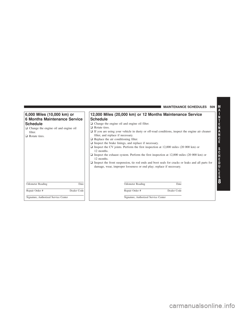
6,000 Miles (10,000 km) or
6 Months Maintenance Service
Schedule
❏Change the engine oil and engine oil
filter.
❏ Rotate tires.
Odometer Reading Date
Repair Order #Dealer Code
Signature, Authorized Service Center
12,000 Miles (20,000 km) or 12 Months Maintenance Service
Schedule
❏Change the engine oil and engine oil filter.
❏ Rotate tires.
❏ If you are using your vehicle in dusty or off-road conditions, inspect the engine air cleaner
filter, and replace if necessary.
❏ Replace the air conditioning filter.
❏ Inspect the brake linings, and replace if necessary.
❏ Inspect the CV joints. Perform the first inspection at 12,000 miles (20 000 km) or
12 months.
❏ Inspect the exhaust system. Perform the first inspection at 12,000 miles (20 000 km) or
12 months.
❏ Inspect the front suspension, tie rod ends and boot seals for cracks or leaks and all parts for
damage, wear, improper looseness or end play; replace if necessary.
Odometer Reading Date
Repair Order #Dealer Code
Signature, Authorized Service Center
8
M
A I
N T
E
N A
N CE
S
C
H E
D
U L
E
SMAINTENANCE SCHEDULES 509