2012 BMW Z4 SDRIVE35I ESP
[x] Cancel search: ESPPage 60 of 220

DisplaysVehicle equipment
This chapter describes all series equipment as
well as country-specific and special equipment
offered for this model series.Therefore, it also
describes equipment that may not be found in
your vehicle, for instance due to the selected
special equipment or the country version. This
also applies to safety-related functions and sys‐
tems.
Odometer, outside
temperature display, clock1Knob in the instrument cluster2Outside temperature display and clock3Odometer and trip odometer
Knob in the instrument cluster
▷To reset the trip odometer while the ignition
is switched on.▷To display the time, external temperature
and odometer briefly while the ignition is
switched off.
Units of measure
To set the respective units of measure, miles or
km for the odometer and ℃ or ℉ for the external
temperature, refer to page 63.
The setting is stored for the remote control cur‐
rently in use.
Time, outside temperature display
Set the time, refer to page 64.
External temperature warning
If the display drops to 37 ℉/3 ℃, a signal sounds
and a warning lamp lights up. There is the in‐
creased danger of ice.
Ice on roads
Even at temperatures above +37 ℉/+3 ℃,
there can be a risk of ice on roads.
Therefore, drive carefully on bridges and shady
roads, for example, to avoid the increased dan‐
ger of an accident.◀
Odometer and trip odometer
Resetting trip odometer:
With the ignition switched on, press button 1 in
the instrument cluster.
When the vehicle is parked
If you still want to view the time, outside tem‐
perature and odometer reading briefly after the
remote control has been taken out of the ignition
lock:
Press button 1 in the instrument cluster.Seite 60ControlsDisplays60
Online Edition for Part no. 01 40 2 609 184 - 09 11 500
Page 62 of 220

▷The remaining range is shown on the com‐
puter.▷When a dynamic driving style is used, such
as when corners are taken rapidly, engine
functions are not ensured.
Below a range of approx. 30 miles/50 km, the
indicator lamp is displayed continuously.
Refuel promptly
At the latest, refuel at a range of 30 miles/
50 km; otherwise, the engine function is not en‐
sured and damage may occur.◀
Computer
Displays in the instrument cluster
Calling up information
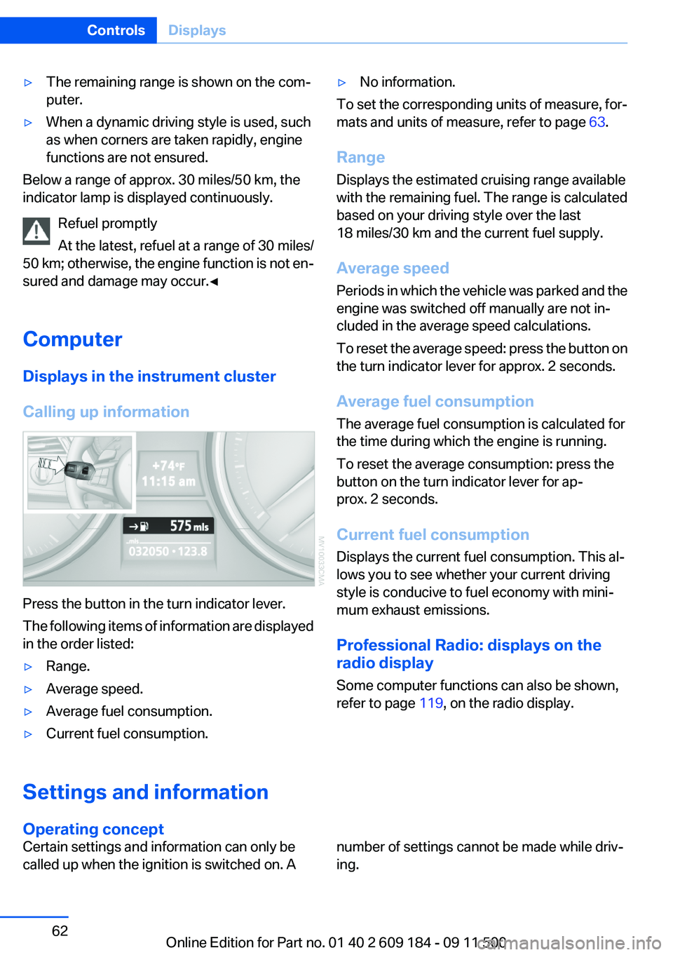
Press the button in the turn indicator lever.
The following items of information are displayed
in the order listed:
▷Range.▷Average speed.▷Average fuel consumption.▷Current fuel consumption.▷No information.
To set the corresponding units of measure, for‐
mats and units of measure, refer to page 63.
Range
Displays the estimated cruising range available
with the remaining fuel. The range is calculated
based on your driving style over the last
18 miles/30 km and the current fuel supply.
Average speed
Periods in which the vehicle was parked and the
engine was switched off manually are not in‐
cluded in the average speed calculations.
To reset the average speed: press the button on
the turn indicator lever for approx. 2 seconds.
Average fuel consumption
The average fuel consumption is calculated for
the time during which the engine is running.
To reset the average consumption: press the
button on the turn indicator lever for ap‐
prox. 2 seconds.
Current fuel consumption
Displays the current fuel consumption. This al‐
lows you to see whether your current driving
style is conducive to fuel economy with mini‐
mum exhaust emissions.
Professional Radio: displays on the
radio display
Some computer functions can also be shown,
refer to page 119, on the radio display.Settings and information
Operating concept
Certain settings and information can only be
called up when the ignition is switched on. Anumber of settings cannot be made while driv‐
ing.Seite 62ControlsDisplays62
Online Edition for Part no. 01 40 2 609 184 - 09 11 500
Page 63 of 220

1Button for:▷Selecting the display▷Setting values2Button for:▷Confirming selected display or set val‐
ues▷Calling up computer information 623With the lights switched on: dimming the in‐
strument lighting 714Calling up Check Control 665Checking the engine oil level 1646Initializing the Flat Tire Monitor 76
Resetting the Tire Pressure Monitor 77.7Setting the time 648Setting the date 659Viewing service requirement display 6510Setting formats and units of measure, re‐
setting to factory settings 6311Changing settings▷Confirmation signals when locking and
unlocking the vehicle 24▷Response during unlocking proce‐
dure 22▷Automatic locking 26▷Headlamp courtesy delay feature 68▷Daytime running lights 69▷Triple turn signal activation 50▷Seat memory 39Exiting displays
The external temperature reading and the time
reappear when you press button 2 or if you make
no entries within approx. 15 seconds. If required,
complete the current setting first.Formats and units of measure
You can set formats and units of measure.1.Switch on the ignition, refer to page 45.2.Lightly push button 1 in the turn indicator
lever up or down repeatedly until the symbolSeite 63DisplaysControls63
Online Edition for Part no. 01 40 2 609 184 - 09 11 500
Page 67 of 220

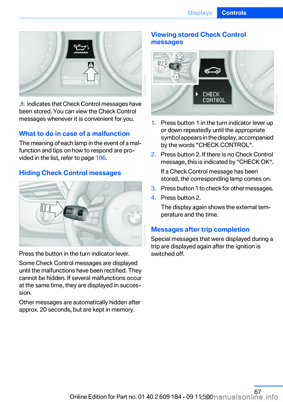
indicates that Check Control messages have
been stored. You can view the Check Control
messages whenever it is convenient for you.
What to do in case of a malfunction
The meaning of each lamp in the event of a mal‐
function and tips on how to respond are pro‐
vided in the list, refer to page 186.
Hiding Check Control messages
Press the button in the turn indicator lever.
Some Check Control messages are displayed
until the malfunctions have been rectified. They
cannot be hidden. If several malfunctions occur
at the same time, they are displayed in succes‐
sion.
Other messages are automatically hidden after
approx. 20 seconds, but are kept in memory.
Viewing stored Check Control
messages1.Press button 1 in the turn indicator lever up
or down repeatedly until the appropriate
symbol appears in the display, accompanied
by the words "CHECK CONTROL".2.Press button 2. If there is no Check Control
message, this is indicated by "CHECK OK“.
If a Check Control message has been
stored, the corresponding lamp comes on.3.Press button 1 to check for other messages.4.Press button 2.
The display again shows the external tem‐
perature and the time.
Messages after trip completion
Special messages that were displayed during a
trip are displayed again after the ignition is
switched off.
Seite 67DisplaysControls67
Online Edition for Part no. 01 40 2 609 184 - 09 11 500
Page 69 of 220

appears in the display, accompanied by the
word "SET".3.Press button 2.4.Lightly push button 1 in the turn indicator
lever down repeatedly until the symbol ap‐
pears in the display.5.Press button 2.6.Use button 1 to select one of the following:▷ The function is deactivated.▷ ... Select the corresponding
duration, 40 seconds, for instance.7.Press button 2.
The setting is stored for the remote control cur‐
rently in use.
Automatic headlamp control
Switch position
: the low beams are switched
on and off automatically, e.g., in tunnels, in twi‐
light or if there is precipitation. The LED next to
the symbol lights up.
A blue sky with the sun low on the horizon can
cause the lights to be switched on.
Personal responsibility
The automatic headlamp control cannot
serve as a substitute for your personal judgment
in determining when the lamps should be
switched on in response to ambient lighting
conditions.
For example, the sensors are unable to detect
fog or hazy weather. To avoid safety risks, you
should always switch on the lamps manually un‐
der these conditions.◀
Daytime running lights
The daytime running lights light up in posi‐
tion 0,
and . After the ignition is
switched off, the parking lamps light up in posi‐
tion
.
Activating/deactivating
Operating principle, refer to page 62.
1.Switch on the ignition.2.Lightly push button 1 in the turn indicator
lever up or down repeatedly until the symbol
appears in the display, accompanied by the
word "SET".3.Press button 2.Seite 69LampsControls69
Online Edition for Part no. 01 40 2 609 184 - 09 11 500
Page 71 of 220

High-beam Assistant
The concept
When the lights are switched on, this system
automatically switches the high beams on and
off. The procedure is controlled by a sensor on
the front of the interior rearview mirror. The as‐
sistant ensures that the high beams are
switched on whenever the traffic situation al‐
lows. The driver can intervene at any time and
switch the high beams on and off as usual.
Activating the High-beam Assistant1.Turn the light switch to .2.With the low beams switched on, briefly
push the turn indicator lever in the direction
of the high beam.
The indicator lamp in the instrument
cluster lights up.
When the lights are switched on, the
high beams are switched on and off automati‐
cally.
The system responds to light from oncoming
traffic and traffic driving ahead of you, and to ad‐
equate illumination, e.g., in towns and cities.
Switching the high beams on and off
manually
▷High beams on, arrow 1.▷High beams off/headlamp flasher, arrow 2.
To reactivate the High-beam Assistant, briefly
push the turn indicator lever toward the high
beams.
System limits
Personal responsibility
The High-beam Assistant cannot serve as
a substitute for the driver's personal judgment
of when to use the high beams. Therefore, man‐
ually switch off the high beams in situations
where this is required to avoid a safety risk.◀
The system is not fully functional in situations
such as the following, and driver intervention
may be necessary:▷In very unfavorable weather conditions,
such as fog or heavy precipitation.▷In detecting poorly-lit road users, such as
pedestrians, cyclists, horseback riders and
wagons; when driving close to train or ship
traffic; and at animal crossings.▷In tight curves, on hilltops or in depressions,
in cross traffic or half-obscured oncoming
traffic on freeways.▷In poorly-lit towns and cities and in the pres‐
ence of highly reflective signs.▷At low speeds.▷When the windshield in front of the interior
rearview mirror is fogged over, dirty or cov‐
ered with stickers, etc.
Sensor view field
The view field of the sensor is located on the
front of the interior rearview mirror.
Do not cover this area with stickers, etc.
Clean the view field, refer to page 185.
Instrument lighting
The parking lamps or low beams must be
switched on to adjust the brightness.
Seite 71LampsControls71
Online Edition for Part no. 01 40 2 609 184 - 09 11 500
Page 73 of 220

SafetyVehicle equipment
This chapter describes all series equipment as
well as country-specific and special equipment
offered for this model series.Therefore, it also
describes equipment that may not be found in
your vehicle, for instance due to the selected
special equipment or the country version. This
also applies to safety-related functions and sys‐
tems.
Airbags
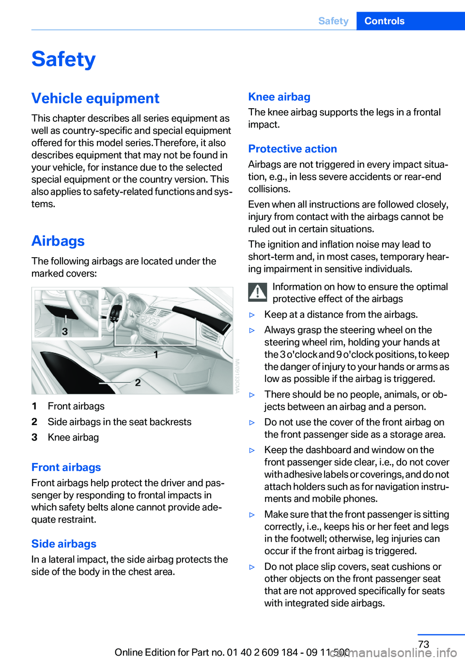
The following airbags are located under the
marked covers:1Front airbags2Side airbags in the seat backrests3Knee airbag
Front airbags
Front airbags help protect the driver and pas‐
senger by responding to frontal impacts in
which safety belts alone cannot provide ade‐
quate restraint.
Side airbags
In a lateral impact, the side airbag protects the
side of the body in the chest area.
Knee airbag
The knee airbag supports the legs in a frontal
impact.
Protective action
Airbags are not triggered in every impact situa‐
tion, e.g., in less severe accidents or rear-end
collisions.
Even when all instructions are followed closely,
injury from contact with the airbags cannot be
ruled out in certain situations.
The ignition and inflation noise may lead to
short-term and, in most cases, temporary hear‐
ing impairment in sensitive individuals.
Information on how to ensure the optimal
protective effect of the airbags▷Keep at a distance from the airbags.▷Always grasp the steering wheel on the
steering wheel rim, holding your hands at
the 3 o'clock and 9 o'clock positions, to keep
the danger of injury to your hands or arms as
low as possible if the airbag is triggered.▷There should be no people, animals, or ob‐
jects between an airbag and a person.▷Do not use the cover of the front airbag on
the front passenger side as a storage area.▷Keep the dashboard and window on the
front passenger side clear, i.e., do not cover
with adhesive labels or coverings, and do not
attach holders such as for navigation instru‐
ments and mobile phones.▷Make sure that the front passenger is sitting
correctly, i.e., keeps his or her feet and legs
in the footwell; otherwise, leg injuries can
occur if the front airbag is triggered.▷Do not place slip covers, seat cushions or
other objects on the front passenger seat
that are not approved specifically for seats
with integrated side airbags.Seite 73SafetyControls73
Online Edition for Part no. 01 40 2 609 184 - 09 11 500
Page 75 of 220

The indicator lamp for the front passenger air‐
bags indicates the operating status of the front
and side airbags on the front passenger side de‐
pending on the seat occupation. The indicator
lamp shows whether the passenger airbags are
activated or deactivated.▷The indicator lamp lights up when a child
who is properly seated in a child restraint
system intended for that purpose is de‐
tected on the seat or the seat is empty. The
front and side airbags on the front passen‐
ger side are not activated. Most child seats
are detected by the system, Especially the
child seats required by NHTSA at the time
that the vehicle was manufactured. After in‐
stalling a child seat, make sure that the indi‐
cator lamp for the front passenger airbags
lights up. This indicates that the child seat
has been detected and the front passenger
airbags are not activated.▷The indicator lamp does not light up when,
for example, a person of sufficient size and
in a correct sitting position is detected on
the seat. The front and front passenger air‐
bags on the front passenger side are acti‐
vated.
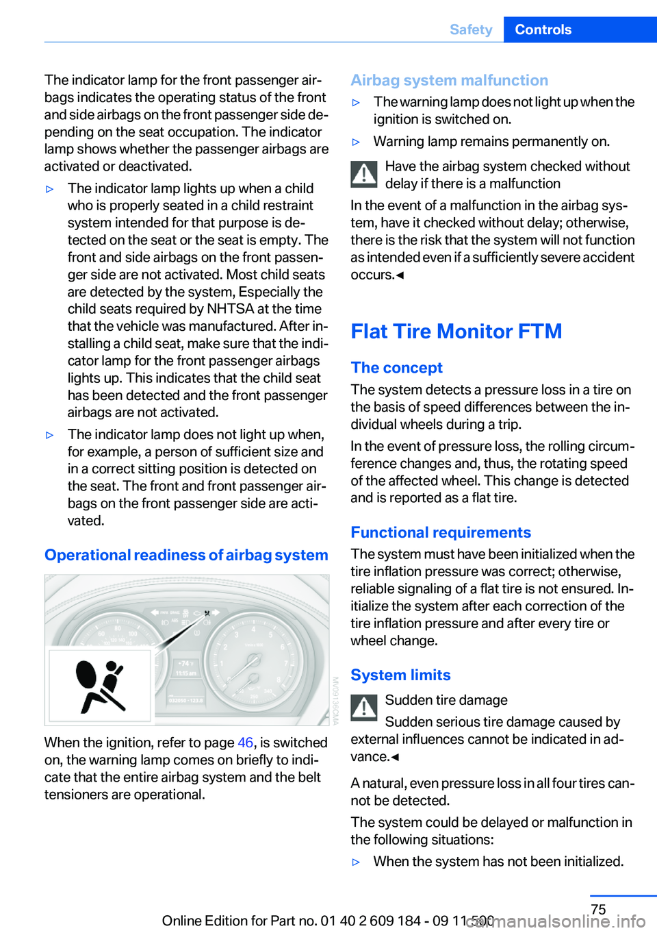
Operational readiness of airbag system
When the ignition, refer to page 46, is switched
on, the warning lamp comes on briefly to indi‐
cate that the entire airbag system and the belt
tensioners are operational.
Airbag system malfunction▷The warning lamp does not light up when the
ignition is switched on.▷Warning lamp remains permanently on.
Have the airbag system checked without
delay if there is a malfunction
In the event of a malfunction in the airbag sys‐
tem, have it checked without delay; otherwise,
there is the risk that the system will not function
as intended even if a sufficiently severe accident
occurs.◀
Flat Tire Monitor FTM
The concept
The system detects a pressure loss in a tire on
the basis of speed differences between the in‐
dividual wheels during a trip.
In the event of pressure loss, the rolling circum‐
ference changes and, thus, the rotating speed
of the affected wheel. This change is detected
and is reported as a flat tire.
Functional requirements
The system must have been initialized when the
tire inflation pressure was correct; otherwise,
reliable signaling of a flat tire is not ensured. In‐
itialize the system after each correction of the
tire inflation pressure and after every tire or
wheel change.
System limits Sudden tire damage
Sudden serious tire damage caused by
external influences cannot be indicated in ad‐
vance.◀
A natural, even pressure loss in all four tires can‐
not be detected.
The system could be delayed or malfunction in
the following situations:
▷When the system has not been initialized.Seite 75SafetyControls75
Online Edition for Part no. 01 40 2 609 184 - 09 11 500