2012 BMW 650I Lighter
[x] Cancel search: LighterPage 129 of 282

To do so:
▷
Read the instructions of the hand-held
transmitter.
▷ Press the memory button of the universal
remote control for an extended period.
If the LED flashes rapidly for a brief period and
then lights up continuously for approx. 2 sec‐
onds, the hand-held transmitter is equipped
with an alternating code system.
In this case, program the memory buttons as
described under Alternating-code hand-held
transmitters.
Alternating-code hand-held
transmitters
Please obtain information on synchronizing the
device
in the operating manual of the device be‐
ing set up.
Programming will be easier with the aid of a sec‐
ond person.
1. Park the vehicle within range of the remote-
controlled device.
2. Program the universal remote control as de‐
scribed above under Fixed-code hand-held
transmitters.
3. Press and hold the programmed button on
the
interior rearview mirror for approx. 5 sec‐
onds until the device to be adjusted is acti‐
vated.
If the device does not become activated,
press and hold the button and watch the
LED:
▷ If the LED lights up continuously, the
programming is completed. The device
should
become activated when the but‐
ton is pressed briefly.
▷ If the LED flashes for approx. 2 seconds
and then lights up continuously, con‐
tinue the programming procedure be‐
ginning with step 4.
4. Locate the button on the receiver of the de‐
vice to be set, e.g., on the drive. 5.
Press the button on the receiver of the de‐
vice
to be set. You have approx. 30 seconds
for the next step.
6. Press the programmed memory button of
the universal remote control three times.
The device can be operated when the engine is
running or the ignition is switched on.
Reassigning individual programs
1. Switch on the ignition.
2. Hold the hand-held transmitter a distance of
approx.
2 to 8 in/5 to 20 cm from the memory
buttons.
3. Press the memory button of the universal
remote control.
4. If the LED flashes slowly after approx.
20 seconds, press the transmit button on
the hand-held transmitter.
5. Release both buttons when the LED flashes
rapidly.
If
the LED does not flash rapidly after approx.
15 seconds, change the distance and repeat
the step.
Deleting all stored programs
Press the left and right memory buttons for ap‐
prox. 20 seconds until the LED flashes rapidly.
All stored programs are deleted.
The programs cannot be deleted individually.
Ashtray/cigarette lighter
*
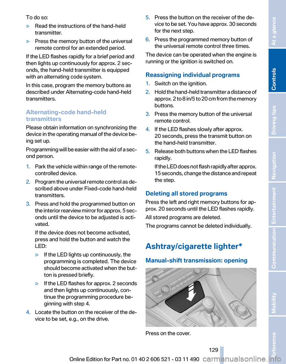
Manual-shift transmission: opening Press on the cover.
Seite 129
129Online Edition for Part no. 01 40 2 606 521 - 03 11 490
Reference Mobility Communication Entertainment Navigation Driving tips
Controls At a glance
Page 130 of 282

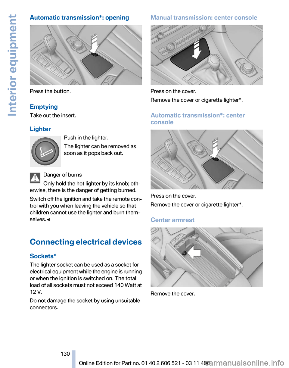
Automatic transmission*: opening
Press the button.
Emptying
Take out the insert.
Lighter
Push in the lighter.
The lighter can be removed as
soon as it pops back out.
Danger of burns
Only hold the hot lighter by its knob; oth‐
erwise, there is the danger of getting burned.
Switch
off the ignition and take the remote con‐
trol with you when leaving the vehicle so that
children cannot use the lighter and burn them‐
selves.◀
Connecting electrical devices
Sockets*
The lighter socket can be used as a socket for
electrical equipment while the engine is running
or when the ignition is switched on. The total
load of all sockets must not exceed 140 Watt at
12 V.
Do not damage the socket by using unsuitable
connectors. Manual transmission: center console
Press on the cover.
Remove the cover or cigarette lighter*.
Automatic transmission
*: center
console Press on the cover.
Remove the cover or cigarette lighter*.
Center armrest
Remove the cover.
Seite 130
130 Online Edition for Part no. 01 40 2 606 521 - 03 11 490
Interior equipment
Page 141 of 282

4.
The resulting figure equals the available
amount
of cargo and luggage load capacity.
For example, if the YYY amount equals
1,000 lbs and there will be four 150 lbs pas‐
sengers in your vehicle, the amount of avail‐
able cargo and luggage load capacity is
400 lbs: 1,000 lbs minus 600 lbs = 400 lbs.
5. Determine the combined weight of luggage
and
cargo being loaded on the vehicle. That
weight may not safely exceed the available
cargo and luggage load capacity calculated
in Step 4.
Load The maximum load is the sum of the weight of
the occupants and the cargo.
The greater the weight of the occupants, the
less cargo that can be transported.
Stowing cargo
▷
Heavy cargo: stow as far forward and as low
as
possible, ideally directly behind the cargo
area separating wall.
▷ Very heavy cargo: when the rear seat is not
occupied, secure each of the outer safety
belts in the opposite buckle.
▷ Cover sharp edges and corners. Securing cargo
Lashing eyes in the cargo area
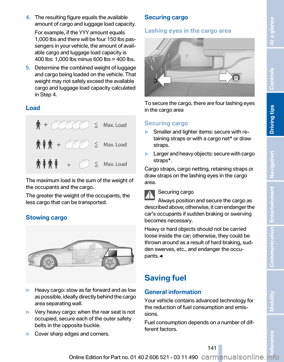
To secure the cargo, there are four lashing eyes
in the cargo area
Securing cargo
▷
Smaller and lighter items: secure with re‐
taining straps or with a
cargo net* or draw
straps.
▷ Larger and heavy objects: secure with cargo
straps*.
Cargo straps, cargo netting, retaining straps or
draw straps on the lashing eyes in the cargo
area.
Securing cargo
Always position and secure the cargo as
described
above; otherwise, it can endanger the
car's occupants if sudden braking or swerving
becomes necessary.
Heavy or hard objects should not be carried
loose inside the car; otherwise, they could be
thrown around as a result of hard braking, sud‐
den swerves, etc., and endanger the occu‐
pants.◀
Saving fuel
General information
Your vehicle contains advanced technology for
the reduction of fuel consumption and emis‐
sions.
Fuel consumption depends on a number of dif‐
ferent factors. Seite 141
141Online Edition for Part no. 01 40 2 606 521 - 03 11 490
Reference Mobility Communication Entertainment Navigation
Driving tips Controls At a glance
Page 252 of 282

Towing other vehicles
General information
Light towing vehicle
Your vehicle must not be lighter than the
vehicle being towed; otherwise, it will not be
possible to control vehicle response.◀
Attaching the tow bar/tow rope correctly
Attach the tow bar or tow rope to the tow
fitting; connecting it to other vehicle parts may
cause damage.◀
▷ Switch on the hazard warning system, de‐
pending on local regulations.
▷ If the electrical system has failed, clearly
identify the vehicle being towed by placing
a sign or a warning triangle in the rear win‐
dow.
Tow bar
The tow fittings used should be on the same
side on both vehicles.
Should it prove impossible to avoid mounting
the tow bar at an offset angle, please observe
the following:
▷ Maneuvering capability is limited during cor‐
nering.
▷ The tow bar will generate lateral forces if it
is secured with an offset.
Tow rope
When starting to tow the vehicle, make sure that
the tow rope is taut.
To avoid jerking and the associated stresses on
the vehicle components when towing, always
use nylon ropes or nylon straps.
Attaching the tow rope correctly
Only secure the tow rope on the tow fit‐
ting; otherwise, damage can occur when it is se‐
cured on other parts of the vehicle.◀ Tow fitting
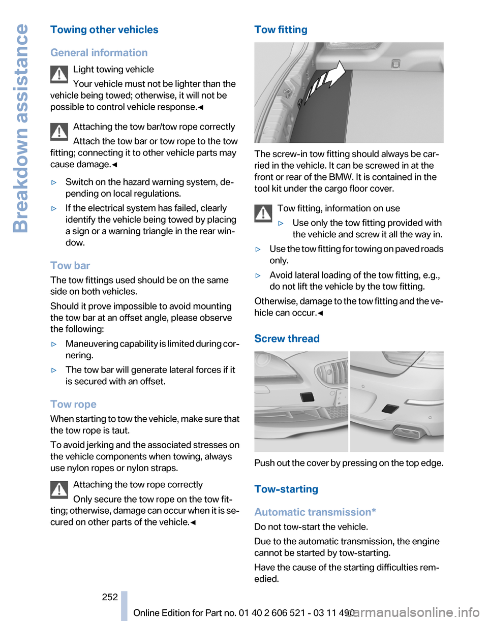
The screw-in tow fitting should always be car‐
ried in the vehicle. It can be screwed in at the
front or rear of the BMW. It is contained in the
tool kit under the cargo floor cover.
Tow fitting, information on use
▷Use only the tow fitting provided with
the vehicle and screw it all the way in.
▷ Use the tow fitting for towing on paved roads
only.
▷ Avoid lateral loading of the tow fitting, e.g.,
do not lift the vehicle by the tow fitting.
Otherwise, damage to the tow fitting and the ve‐
hicle can occur.◀
Screw thread Push out the cover by pressing on the top edge.
Tow-starting
Automatic transmission
*
Do not tow-start the vehicle.
Due to the automatic transmission, the engine
cannot be started by tow-starting.
Have the cause of the starting difficulties rem‐
edied. Seite 252
252 Online Edition for Part no. 01 40 2 606 521 - 03 11 490
Breakdown assistance
Page 273 of 282

BMW Internet page
6
BMW Maintenance Sys‐ tem 241
BMW Online 220
Bottle holder, refer to Cu‐ pholder 133
Brake assistant 101
Brake discs, breaking in 138
Brake force display 100
Brake lamps, brake force dis‐ play 100
Brake lamps, bulb replace‐ ment 245
Brake lights, adaptive 100
Brake pads, breaking in 138
Braking, notes 139
Breakdown assis‐ tance 248, 249
Breaking in 138
Brightness of Control Dis‐ play 80
Bulb replacement 243
Bulb replacement, front 244
Bulb replacement, rear 245
Bulbs and lamps 243
Button, Start/Stop 65
Bypassing, refer to starting aid 249
C
Calendar 212
California Proposition 65 Warning 7
Camera, backup camera 112
Camera, care 257
Camera, Side View 115
Camera, Top View 114
Can holder, refer to Cu‐ pholder 133
Car battery 247
Car care products 255
Care, displays 257
Care, vehicle 255
Cargo 140
Cargo area, cargo area parti‐ tion 47
Cargo area lid 40 Cargo area partition
47
Cargo area, storage compart‐ ments 134
Cargo straps, securing cargo 141
Car key, refer to Remote con‐ trol 32
Carpet, care 256
Car wash 254
Catalytic converter, refer to Hot exhaust system 138
CBS Condition Based Serv‐ ice 241
CD/DVD 173
CDs, storing 180
Cell phone 196
Center armrest 132
Center console 17
Central locking system 35
Central
screen, refer to Control
Display 19
Changes, technical, refer to Safety 7
Changing parts 243
Changing wheels/tires 233
Check Control 82
Children, seating position 62
Children, transporting safely 62
Child restraint fixing sys‐ tem 62
Child restraint fixing system LATCH 63
Child restraint fixing systems, mounting 62
Child seat, mounting 62
Child seats 62
Chrome parts, care 256
Cigarette lighter 129
Cleaning, displays 257
Climate control 123
Climate control wind‐ shield 139
Clock 76
Closing/opening from in‐ side 39
Closing/opening via door lock 38 Closing/opening with remote
control 36
Combination instrument 14
Combination
instrument, elec‐
tronic displays 16
Combination switch, refer to Turn signals 69
Combination switch, refer to Wiper system 69
Comfort Access 41
COMFORT program, Dynamic Driving Control 105
Computer 76
Concierge service 219
Condensation on win‐ dows 124
Condensation under the vehi‐ cle 140
Condition Based Service CBS 241
Confirmation signal 37
Contacts 207, 216
Control Display 19
Control Display, settings 79
Controller 19
Control systems, driving sta‐ bility 101
Convenient closing 37
Convenient opening 36
Convertible, convertible top 45
Convertible mode, automatic climate control 124
Convertible program, auto‐ matic climate control 124
Convertible top 45
Convertible top, care 255
Convertible top, cargo area partition 47
Convertible top, emergency operation 47
Convertible top, rollover pro‐ tection system 91
Convertible top tool 47
Coolant 239
Coolant temperature 75
Cooling function 125
Cooling, maximum 124
Seite 273
273Online Edition for Part no. 01 40 2 606 521 - 03 11 490
Reference Mobility Communication Entertainment Navigation Driving tips Controls At a glance