2012 BMW 650I change time
[x] Cancel search: change timePage 103 of 282
The rear wheels are turned to the same angle as
the front wheels.
In
critical situations, Integral Active Steering can
specifically steer the front and rear wheels to
stabilize the vehicle before the driver intervenes,
e.g., when braking where road conditions differ
on the left and right sides of the vehicle.
Initializing
In rare cases, it may become necessary to initi‐
alize the Integral Active Steering.
The warning lamp lights up. A Check
Control message is displayed.
1. With the engine running, turn the steering
wheel
all the way to the left and right several
times in a uniform manner until the warning
lamp disappears.
2. Have the system checked if the warning
lamp
does not go out after moving the steer‐
ing wheel approx. 6 times or if the steering
wheel is at an angle.
Using snow chains
Ensure
that the rear axle steering is deactivated
when using snow chains, refer to page 235.
Programs
The system offers two different programs.
The programs can be selected via Dynamic Driv‐
ing Control, refer to page 103.
SPORT
Consistently sporty tuning of the Integral Active
Steering for greater driving agility.
NORMAL
Balanced tuning of the Integral Active Steering
for optimal traveling comfort.
Malfunction
In the event of a malfunction, the steering wheel
must be turned further, while the vehicle re‐
sponds more sensitively to steering wheel
movements in the higher speed range. The stability-enhancing intervention may be de‐
activated.
Proceed cautiously and drive defensively.
Have the system checked.
Dynamic Driving Control*
The concept
Dynamic Driving Control can be used to adjust
the
driving dynamics of the vehicle. Several pro‐
grams are available for this purpose; they can be
activated using the two Dynamic Driving Control
buttons.
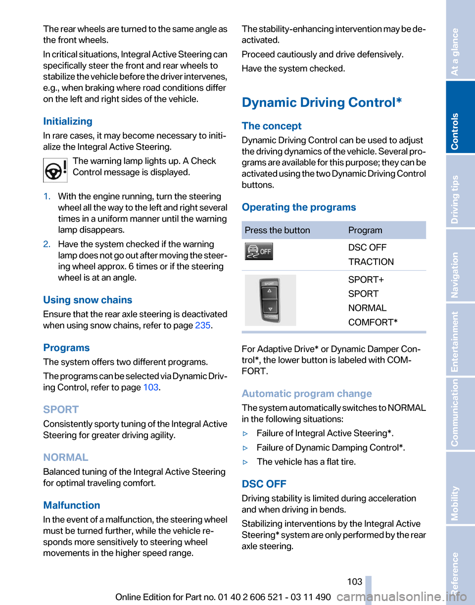
Operating the programs Press the button Program
DSC OFF
TRACTION
SPORT+
SPORT
NORMAL
COMFORT*
For Adaptive Drive* or Dynamic Damper Con‐
trol*, the lower button is labeled with COM‐
FORT.
Automatic program change
The
system automatically switches to NORMAL
in the following situations:
▷ Failure of Integral Active Steering*.
▷ Failure of Dynamic Damping Control*.
▷ The vehicle has a flat tire.
DSC OFF
Driving stability is limited during acceleration
and when driving in bends.
Stabilizing interventions by the
Integral Active
Steering* system are only performed by the rear
axle steering.
Seite 103
103Online Edition for Part no. 01 40 2 606 521 - 03 11 490
Reference Mobility Communication Entertainment Navigation Driving tips
Controls At a glance
Page 107 of 282
Change, maintain speed
The rocker switch can be pressed while inter‐
rupted to maintain and store the current speed.
Adapting the desired speed
Adapt the desired speed to the road con‐
ditions
and be ready to brake at all times; other‐
wise, there is the danger of an accident occur‐
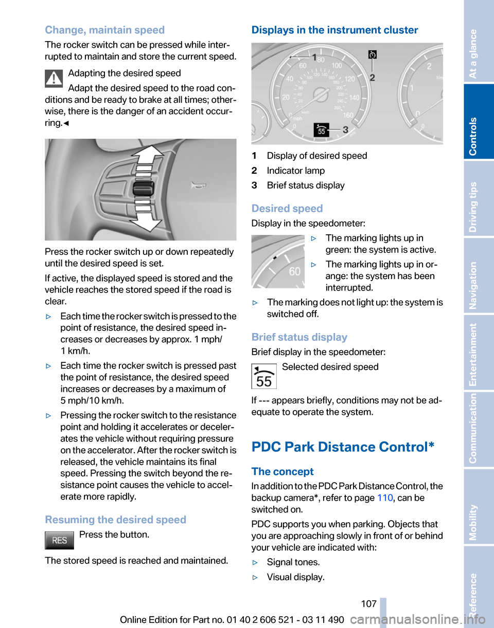
ring.◀ Press the rocker switch up or down repeatedly
until the desired speed is set.
If active, the displayed speed is stored and the
vehicle reaches the stored speed if the road is
clear.
▷
Each time the rocker switch is pressed to the
point of resistance, the desired speed in‐
creases or decreases by approx. 1 mph/
1 km/h.
▷ Each time the rocker switch is pressed past
the point of resistance, the desired speed
increases or decreases by a maximum of
5 mph/10 km/h.
▷ Pressing the rocker switch to the resistance
point and holding it accelerates or deceler‐
ates the vehicle without requiring pressure
on
the accelerator. After the rocker switch is
released, the vehicle maintains its final
speed. Pressing the switch beyond the re‐
sistance point causes the vehicle to accel‐
erate more rapidly.
Resuming the desired speed Press the button.
The stored speed is reached and maintained. Displays in the instrument cluster
1
Display of desired speed
2 Indicator lamp
3 Brief status display
Desired speed
Display in the speedometer: ▷The marking lights up in
green: the system is active.
▷ The marking lights up in or‐
ange: the system has been
interrupted.
▷ The marking does not light up: the system is
switched off.
Brief status display
Brief display in the speedometer: Selected desired speed
If --- appears briefly, conditions may not be ad‐
equate to operate the system.
PDC Park Distance Control*
The concept
In
addition to the PDC Park Distance Control, the
backup camera*, refer to page 110, can be
switched on.
PDC supports you when parking. Objects that
you are approaching slowly in front of or behind
your vehicle are indicated with:
▷ Signal tones.
▷ Visual display. Seite 107
107Online Edition for Part no. 01 40 2 606 521 - 03 11 490
Reference Mobility Communication Entertainment Navigation Driving tips
Controls At a glance
Page 117 of 282

Notes
▷
The parking assistant takes control of steer‐
ing
for as long as the symbol for active park‐
ing appears on the display.
▷ The system maneuvers the vehicle to posi‐
tion
it properly in smaller parking spaces, for
example.
▷ To achieve the best possible parking posi‐
tion, wait for the automatic steering wheel
movement after the gear change when the
vehicle is stationary.
▷ When parking in parking spaces on the driv‐
er's
side, the corresponding turn signal must
be set.
Interrupting manually
The parking assistant can be interrupted at any
time by:
▷ Grasping the steering wheel and steering
yourself.
▷ "Deactivate Parking Assistant" Select
the symbol on the Control Display.
Interrupting automatically
The procedure is interrupted automatically:
▷ If the vehicle speed exceeds approx. 6 mph/
10 km/h.
▷ On snow-covered or slippery road surfaces
if necessary.
▷ If doors are open.
A Check Control message is displayed.
Continuing
An interrupted parking procedure can be con‐
tinued if necessary.
Follow
the instructions on the Control Display to
do this.
Switching off
The system can be deactivated as follows:
▷ Press the button. ▷
Switch off the ignition. Malfunction
A Check Control message is displayed.
The parking assistant failed. Have the system
checked.
System limits
Changes to the parking space
Changes to the parking space after it was
measured
are not taken into account by the sys‐
tem.
Therefore, always be alert and ready to inter‐
vene; otherwise, there is the danger of an acci‐
dent occurring.◀
Transporting loads
Loads that extend beyond the perimeter
of the vehicle are not taken into account by the
system during the parking procedure.
Therefore, always be alert and ready to inter‐
vene; otherwise, there is the danger of an acci‐
dent occurring.◀
Curbs
The parking assistant may steer the vehi‐
cle over or onto curbs.
Therefore, always be alert and ready to inter‐
vene; otherwise, the wheels, tires, or the vehicle
may become damaged.◀
No parking assistance
The parking assistant does not provide assis‐
tance in parking.
▷ In tight curves.
Functional limitations
The system may not be fully functional in the
following situations:
▷ When sensors are dirty or iced over.
▷ In heavy fog, rain or snowfall.
▷ On bumpy road surfaces such as gravel
roads.
▷ When leaves or snow has collected in the
parking space. Seite 117
117Online Edition for Part no. 01 40 2 606 521 - 03 11 490
Reference Mobility Communication Entertainment Navigation Driving tips
Controls At a glance
Page 125 of 282

Automatic recirculated-air control/
recirculated-air mode
You can respond to unpleasant odors or pollu‐
tants in the immediate environment by tempo‐
rarily suspending the supply of outside air. The
system
then recirculates the air currently within
the vehicle.
Press the button repeatedly to select
an operating mode:
▷ LEDs off: outside air flows in continuously.
▷ Left LED on, automatic recirculated-air con‐
trol: a sensor detects pollutants in the out‐
side air and controls the shut-off automati‐
cally.
▷ Right LED on, recirculated-air mode: the
supply of outside air into the vehicle is per‐
manently blocked.
If the windows are fogged over, switch off the
recirculated-air
mode and press the AUTO but‐
ton on the driver's side to utilize the condensa‐
tion sensor. Make sure that air can flow onto the
windshield.
Continuous recirculated-air mode
The recirculated-air mode should not be
used for an extended period of time, as the air
quality inside the vehicle deteriorates steadily.◀
Cooling function
The passenger compartment can only be
cooled with the engine running.
Press the button.
The air is cooled and dehumidified and
– depending on the temperature setting –
warmed again.
Depending on the weather, the windshield may
fog up briefly when the engine is started.
The cooling function is switched on automati‐
cally with the AUTO program.
When using the automatic climate control, con‐
densation water, refer to page 140, develops
that exits underneath the vehicle. Rear window defroster
Press the button.
The
rear window defroster switches off
automatically after a certain period of time.
The rear window defroster is only active when
the rear window is closed.
ALL program
Press the button.
Current settings on the driver's side for
the temperature, air volume, air distribution, and
AUTO program are transferred to the front pas‐
senger side.
The program is switched off if the settings on
the front passenger side are changed.
Residual heat
The heat stored in the engine is used to heat the
interior.
Functional requirement
▷ Up to 20 minutes after the engine has been
switched off.
▷ Warm engine.
▷ The battery is sufficiently charged.
▷ External temperature below 77 ℉/25 ℃.
Switching on
1. Switch off the ignition.
2. Press the right side of the button on
the driver's side. is shown on the display of the automatic cli‐
mate control.
The
interior temperature, air volume and air dis‐
tribution can be adjusted with the ignition
switched on.
Switching off
At the lowest fan speed, press the left side of the
button on the driver's side. on the display of the automatic climate control
goes out. Seite 125
125Online Edition for Part no. 01 40 2 606 521 - 03 11 490
Reference Mobility Communication Entertainment Navigation Driving tips
Controls At a glance
Page 129 of 282
To do so:
▷
Read the instructions of the hand-held
transmitter.
▷ Press the memory button of the universal
remote control for an extended period.
If the LED flashes rapidly for a brief period and
then lights up continuously for approx. 2 sec‐
onds, the hand-held transmitter is equipped
with an alternating code system.
In this case, program the memory buttons as
described under Alternating-code hand-held
transmitters.
Alternating-code hand-held
transmitters
Please obtain information on synchronizing the
device
in the operating manual of the device be‐
ing set up.
Programming will be easier with the aid of a sec‐
ond person.
1. Park the vehicle within range of the remote-
controlled device.
2. Program the universal remote control as de‐
scribed above under Fixed-code hand-held
transmitters.
3. Press and hold the programmed button on
the
interior rearview mirror for approx. 5 sec‐
onds until the device to be adjusted is acti‐
vated.
If the device does not become activated,
press and hold the button and watch the
LED:
▷ If the LED lights up continuously, the
programming is completed. The device
should
become activated when the but‐
ton is pressed briefly.
▷ If the LED flashes for approx. 2 seconds
and then lights up continuously, con‐
tinue the programming procedure be‐
ginning with step 4.
4. Locate the button on the receiver of the de‐
vice to be set, e.g., on the drive. 5.
Press the button on the receiver of the de‐
vice
to be set. You have approx. 30 seconds
for the next step.
6. Press the programmed memory button of
the universal remote control three times.
The device can be operated when the engine is
running or the ignition is switched on.
Reassigning individual programs
1. Switch on the ignition.
2. Hold the hand-held transmitter a distance of
approx.
2 to 8 in/5 to 20 cm from the memory
buttons.
3. Press the memory button of the universal
remote control.
4. If the LED flashes slowly after approx.
20 seconds, press the transmit button on
the hand-held transmitter.
5. Release both buttons when the LED flashes
rapidly.
If
the LED does not flash rapidly after approx.
15 seconds, change the distance and repeat
the step.
Deleting all stored programs
Press the left and right memory buttons for ap‐
prox. 20 seconds until the LED flashes rapidly.
All stored programs are deleted.
The programs cannot be deleted individually.
Ashtray/cigarette lighter
*
Manual-shift transmission: opening Press on the cover.
Seite 129
129Online Edition for Part no. 01 40 2 606 521 - 03 11 490
Reference Mobility Communication Entertainment Navigation Driving tips
Controls At a glance
Page 153 of 282
Store the trip
Up to 30 trips can be stored in the trip list. If
necessary, delete existing trips to be able to
store new trips.
1.
Open "Options".
2. "Store trip"
3. Enter the name.
4. "OK"
Select the stored trip
1. "Navigation"
2. "Stored trips"
3. Select a stored trip.
4. "Start guidance"
Reversing the direction of travel
Intermediate destinations are displayed in re‐
verse order in the list.
1. "Map"
2. "Guidance"
3. Open "Options".
4. "Reverse order of trip dest."
Intermediate destination options
1. "Map"
2. "Guidance"
3. "Display all trip destinations"
4. Select an intermediate destination.
▷"Edit destination"
▷ "Reposition dest. in the trip": move an
intermediate destination to another po‐
sition in the list.
▷ "Delete dest. in the trip"
▷ "Go to next dest. in the trip"
Some options are not available for certain trips.
Delete the stored trip
1. "Stored trips"
2. Highlight the desired trip.
3. Open "Options".
4. "Delete all trips" or "Delete trip" Open the last trip
1.
"Navigation"
2. "Stored trips"
3. "Last trip"
4. "Start guidance"
Destination guidance
Starting destination guidance
1. "Navigation"
2. Make a destination entry, refer to page 146.
3. "Accept destination"
4. "Start guidance"
▷ The route is shown on the Control Display.
▷ The distance to the destination/intermedi‐
ate
destination and the estimated time of ar‐
rival are displayed in the map view.
▷ The arrow view is shown in the instrument
cluster,
in the Head-up Display*, and on the
Control Display where appropriate.
Terminating destination guidance
1. "Navigation"
2. "Map"
3. "Guidance"
4. "Stop guidance"
Continuing destination guidance
If
the destination was not reached during the last
trip, destination guidance can be resumed.
"Resume guidance"
Route criteria
General information
▷ The route calculated can be influenced by
selecting certain criteria.
▷ The route criteria can be changed when the
destination is entered and during destina‐
tion guidance.
Seite 153
153Online Edition for Part no. 01 40 2 606 521 - 03 11 490
Reference Mobility Communication Entertainment
Navigation Driving tips Controls At a glance
Page 154 of 282
▷
Road types are part of the navigation data
and
are taken into consideration when plan‐
ning a route, e.g., avoid highways.
▷ The recommended route may differ from the
route
you would take based on personal ex‐
perience.
▷ The settings are stored for the remote con‐
trol currently in use.
▷ Destination guidance with traffic bulletins,
refer to page 159.
Changing the route criteria
1. "Navigation"
2. "Map"
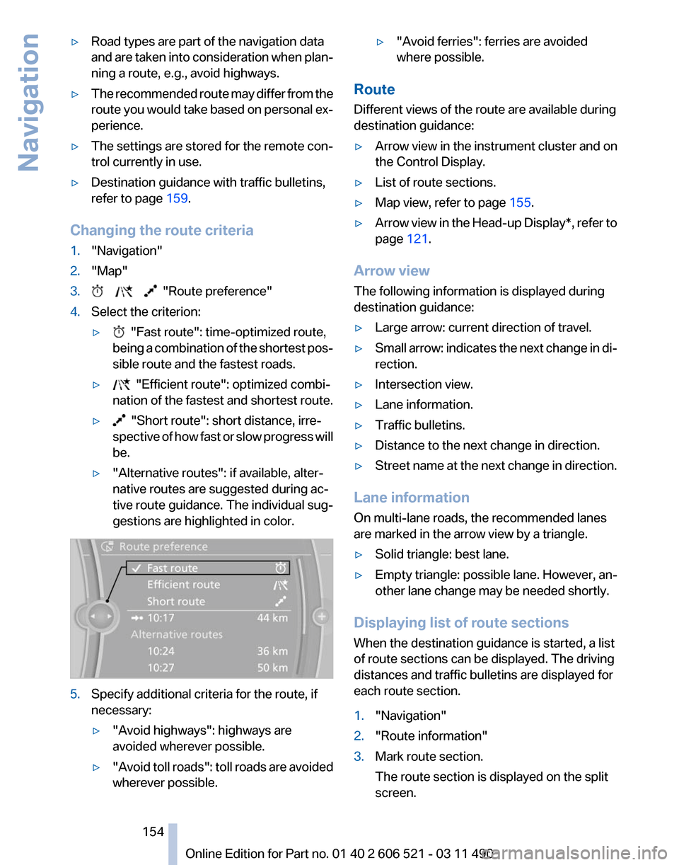
3. "Route preference"
4. Select the criterion:
▷ "Fast route": time-optimized route,
being
a combination of the shortest pos‐
sible route and the fastest roads.
▷ "Efficient route": optimized combi‐
nation of the fastest and shortest route.
▷ "Short route": short distance, irre‐
spective
of how fast or slow progress will
be.
▷ "Alternative routes": if available, alter‐
native routes are suggested during ac‐
tive route guidance. The individual sug‐
gestions are highlighted in color. 5.
Specify additional criteria for the route, if
necessary:
▷"Avoid highways": highways are
avoided wherever possible.
▷ "Avoid
toll roads": toll roads are avoided
wherever possible. ▷
"Avoid ferries": ferries are avoided
where possible.
Route
Different views of the route are available during
destination guidance:
▷ Arrow view in the instrument cluster and on
the Control Display.
▷ List of route sections.
▷ Map view, refer to page 155.
▷ Arrow view in the Head-up Display*, refer to
page 121.
Arrow view
The following information is displayed during
destination guidance:
▷ Large arrow: current direction of travel.
▷ Small arrow: indicates the next change in di‐
rection.
▷ Intersection view.
▷ Lane information.
▷ Traffic bulletins.
▷ Distance to the next change in direction.
▷ Street name at the next change in direction.
Lane information
On multi-lane roads, the recommended lanes
are marked in the arrow view by a triangle.
▷ Solid triangle: best lane.
▷ Empty triangle: possible lane. However, an‐
other lane change may be needed shortly.
Displaying list of route sections
When the destination guidance is started, a list
of route sections can be displayed. The driving
distances and traffic bulletins are displayed for
each route section.
1. "Navigation"
2. "Route information"
3. Mark route section.
The route section is displayed on the split
screen.
Seite 154
154 Online Edition for Part no. 01 40 2 606 521 - 03 11 490
Navigation
Page 156 of 282
At a glance
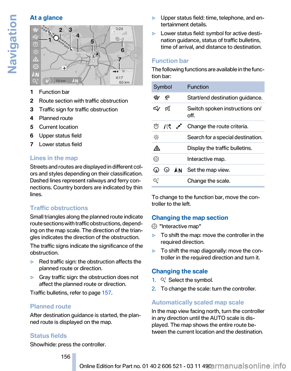
1
Function bar
2 Route section with traffic obstruction
3 Traffic sign for traffic obstruction
4 Planned route
5 Current location
6 Upper status field
7 Lower status field
Lines in the map
Streets and routes are displayed in different col‐
ors and styles depending on their classification.
Dashed lines represent railways and ferry con‐
nections. Country borders are indicated by thin
lines.
Traffic obstructions
Small triangles along the planned route indicate
route sections with traffic obstructions, depend‐
ing on the map scale. The direction of the trian‐
gles indicates the direction of the obstruction.
The traffic signs indicate the significance of the
obstruction.
▷ Red traffic sign: the obstruction affects the
planned route or direction.
▷ Gray traffic sign: the obstruction does not
affect the planned route or direction.
Traffic bulletins, refer to page 157.
Planned route
After destination guidance is started, the plan‐
ned route is displayed on the map.
Status fields
Show/hide: press the controller. ▷
Upper status field: time, telephone, and en‐
tertainment details.
▷ Lower status field: symbol for active desti‐
nation guidance, status of traffic bulletins,
time of arrival, and distance to destination.
Function bar
The
following functions are available in the func‐
tion bar: Symbol Function
Start/end destination guidance.
Switch spoken instructions on/
off. Change the route criteria.
Search for a special destination. Display the traffic bulletins.
Interactive map. Set the map view.
Change the scale. To change to the function bar, move the con‐
troller to the left.
Changing the map section
"Interactive map"
▷ To shift the map: move the controller in the
required direction.
▷ To shift the map diagonally: move the con‐
troller in the required direction and turn it.
Changing the scale
1. Select the symbol.
2. To change the scale: turn the controller.
Automatically scaled map scale
In the map view facing north, turn the controller
in any direction until the AUTO scale is dis‐
played. The map shows the entire route be‐
tween the current location and the destination.
Seite 156
156 Online Edition for Part no. 01 40 2 606 521 - 03 11 490
Navigation