2012 BMW 650I emergency release
[x] Cancel search: emergency releasePage 47 of 282

▷
Right LED flashes red after the switch is re‐
leased:
operating sequence has not yet con‐
cluded.
▷ Right LED comes on red when the switch is
pulled: cargo area partition is flipped up,
trunk lid is not closed or there is a malfunc‐
tion. Convertible top cannot be moved.
In addition to the red LED, a check control mes‐
sage is displayed.
Interruption
Always open/close the convertible top
completely
A convertible top that is not opened or closed
completely is not locked and represents a haz‐
ard.◀
The convertible top movement is interrupted if
the switch is released. The sequence can be
continued in the desired direction using the
switch.
If there is a longer interruption, convertible top
and convertible top well storage cover remain
approx. 10 minutes in the current position be‐
fore they slowly go down. The convertible top
and the convertible top well storage cover are
not locked. Operate switch again until the con‐
vertible operation is terminated.
Convenient operation* from outside
When
equipped with Comfort Access* the con‐
vertible top can also be operated from outside:
▷ Convenient opening with remote operation,
refer to page 36.
▷ Convenient closing with the remote control,
refer to page 37.
▷ Convenient closing via the door handles, re‐
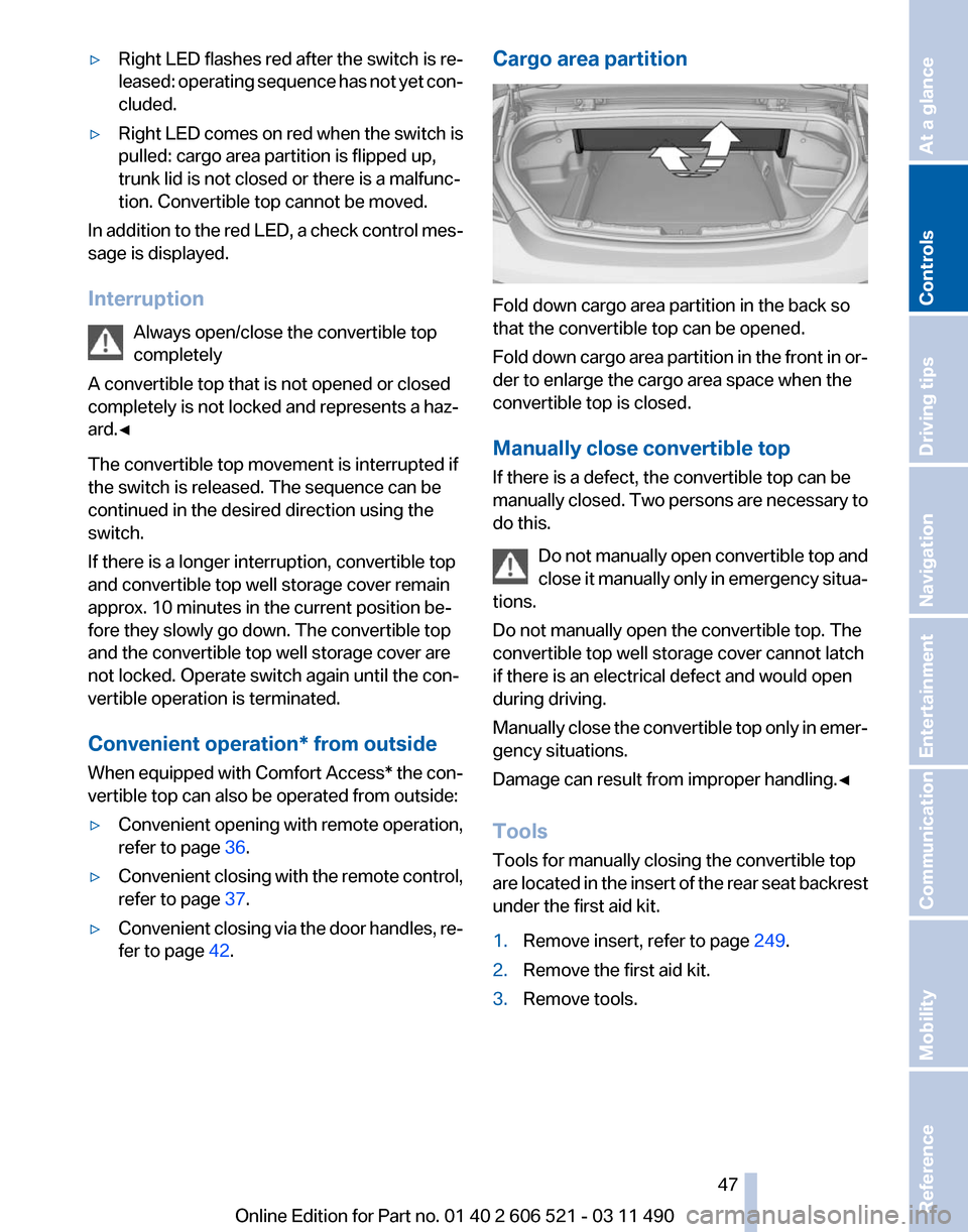
fer to page 42. Cargo area partition
Fold down cargo area partition in the back so
that the convertible top can be opened.
Fold
down cargo area partition in the front in or‐
der to enlarge the cargo area space when the
convertible top is closed.
Manually close convertible top
If there is a defect, the convertible top can be
manually closed. Two persons are necessary to
do this.
Do not manually open convertible top and
close it manually only in emergency situa‐
tions.
Do not manually open the convertible top. The
convertible top well storage cover cannot latch
if there is an electrical defect and would open
during driving.
Manually close the convertible top only in emer‐
gency situations.
Damage can result from improper handling.◀
Tools
Tools for manually closing the convertible top
are located in the insert of the rear seat backrest
under the first aid kit.
1. Remove insert, refer to page 249.
2. Remove the first aid kit.
3. Remove tools. Seite 47
47Online Edition for Part no. 01 40 2 606 521 - 03 11 490
Reference Mobility Communication Entertainment Navigation Driving tips
Controls At a glance
Page 91 of 282

Rollover protection system
The concept
The
rollover protection system is activated dur‐
ing an accident or a critical driving situation,
when there is extreme tilt with respect to the
longitudinal axis or when there is loss of ground
contact. The safety frames located behind the
rear headrests extend within fractions of a sec‐
ond.
In addition to the rollover bracket integrated in
the front windshield frame, the rollover protec‐
tion system guarantees the required head clear‐
ance of all vehicle occupants.
Maintaining movement space
Always keep the movement space of the
rollover protection system clear. Otherwise,
there may be damage or injuries when the roll‐
over protection system is triggered.◀
In less severe accidents, the secured safety belt
and, depending on the severity of the accident,
the belt tensioner and airbag restraint system
provide protection.
Triggered rollover protection system
After deployment or damage
After deployment of the rollover protec‐
tion system or in the event of damage, have the
system checked and replaced.
Have this work performed only by your service
center; otherwise, it cannot be ensured that this
safety feature will function properly.◀
Do not move convertible top
When the rollover protection system is ex‐
tended, do not move the convertible top. Oth‐
erwise, damages or injuries may result.◀
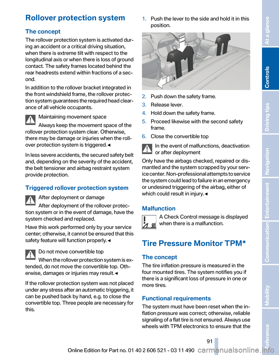
If the rollover protection system was not placed
under any stress after an automatic triggering, it
can be pushed back by hand, e.g. to close the
convertible top. Three people are necessary for
this. 1.
Push the lever to the side and hold it in this
position. 2.
Push down the safety frame.
3. Release lever.
4. Hold down the safety frame.
5. Proceed likewise with the second safety
frame.
6. Close the convertible top
In the event of malfunctions, deactivation
or after deployment
Only have the airbags checked, repaired or dis‐
mantled
and the system scrapped by your serv‐
ice center. Non-professional attempts to service
the system could lead to failure in an emergency
or undesired triggering of the airbag, either of
which could result in injury.◀
Malfunction
A Check Control message is displayed
when there is a malfunction.
Tire Pressure Monitor TPM*
The concept
The tire inflation pressure is measured in the
four mounted tires. The system notifies you if
there is a significant loss of pressure in one or
more tires.
Functional requirements
The system must have been reset when the in‐
flation pressure was correct; otherwise, reliable
signaling of a flat tire is not ensured. Always use
wheels with TPM electronics to ensure that the Seite 91
91Online Edition for Part no. 01 40 2 606 521 - 03 11 490
Reference Mobility Communication Entertainment Navigation Driving tips
Controls At a glance
Page 249 of 282

Assist Response Center may still be able to
hear you.
Initiating an Emergency Request
automatically
Under certain conditions, an Emergency Re‐
quest is automatically initiated immediately after
a severe accident. Automatic Collision Notifica‐
tion is not affected by pressing the SOS button.
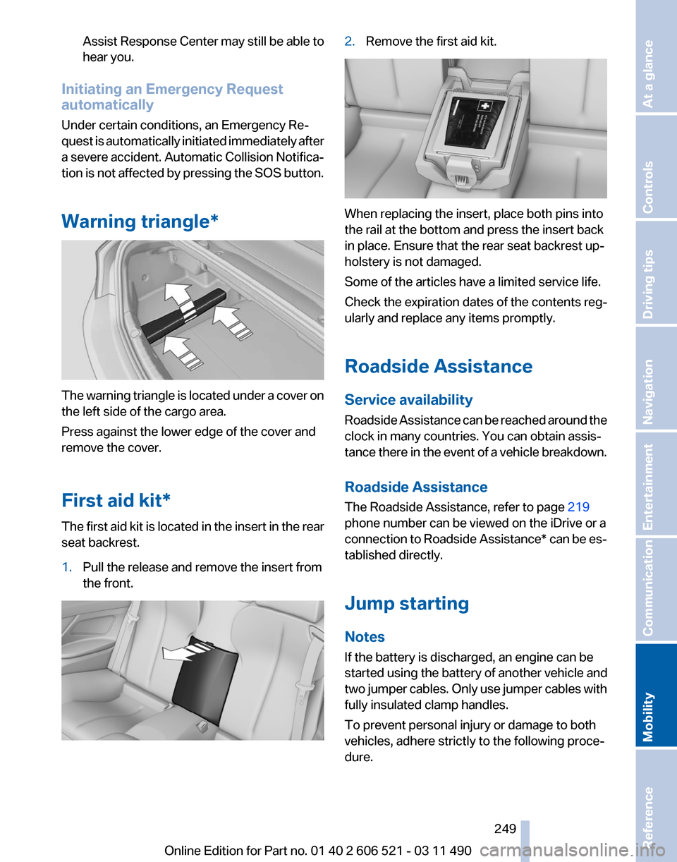
Warning triangle* The warning triangle is located under a cover on
the left side of the cargo area.
Press against the lower edge of the cover and
remove the cover.
First aid kit*
The first aid kit is located in the insert in the rear
seat backrest.
1.
Pull the release and remove the insert from
the front. 2.
Remove the first aid kit. When replacing the insert, place both pins into
the rail at the bottom and press the insert back
in place. Ensure that the rear seat backrest up‐
holstery is not damaged.
Some of the articles have a limited service life.
Check the expiration dates of the contents reg‐
ularly and replace any items promptly.
Roadside Assistance
Service availability
Roadside Assistance can be reached around the
clock in many countries. You can obtain assis‐
tance there in the event of a vehicle breakdown.
Roadside Assistance
The Roadside Assistance, refer to page
219
phone number can be viewed on the iDrive or a
connection to Roadside Assistance* can be es‐
tablished directly.
Jump starting
Notes
If the battery is discharged, an engine can be
started using the battery of another vehicle and
two jumper cables. Only use jumper cables with
fully insulated clamp handles.
To prevent personal injury or damage to both
vehicles, adhere strictly to the following proce‐
dure.
Seite 249
249Online Edition for Part no. 01 40 2 606 521 - 03 11 490
Reference
Mobility Communication Entertainment Navigation Driving tips Controls At a glance
Page 274 of 282

Cooling system
239
Corrosion on brake discs 140
Cruise control 106
Cruising range 74
Cupholder 133
Current fuel consumption 75
Current location, storing 148
Customer Relations 221
D
Damage, tires 232
Damping control, dy‐ namic 102
Data, technical 260
Date 76
Daytime running lights 85
Defrosting, refer to Windows, defrosting 124
Destination distance 77
Destination guidance 153
Destination guidance with in‐ termediate destinations 152
Destination input, naviga‐ tion 146
Digital clock 76
Digital radio 167
Dimensions 260
Dimmable interior rearview mirror 60
Direction indicator, refer to Turn signals 69
Display in front wind‐ shield 121
Display,
instrument cluster 74
Display lighting, refer to Instru‐ ment lighting 87
Displays 14
Displays, cleaning 257
Disposal, coolant 240
Disposal, vehicle battery 247
Distance control, refer to PDC 107
Distance to destination 77
Divided screen view, split screen 23
Door lock, refer to Remote control 32 Doors, Automatic Soft Clos‐
ing 40
Drive-off assistant 101
Drive-off assistant, refer to DSC 101
Driving instructions, breaking in 138
Driving notes, general 138
Driving stability control sys‐ tems 101
Driving tips 138
DSC Dynamic Stability Con‐ trol 101
DTC Dynamic Traction Con‐ trol 101
DVD/CD 173
DVD/CD notes 179
DVD changer 177
DVD settings 176
DVDs, storing 180
DVD, video 175
Dynamic Damping Con‐ trol 102
Dynamic destination guid‐ ance 159
Dynamic Drive 102
Dynamic Driving Control 103
Dynamic Stability Control DSC 101
Dynamic Traction Control DTC 101
E
EfficientDynamics, refer to Saving fuel 141
Electronic displays, instru‐ ment cluster 16
Electronic engine oil level check 238
Electronic Stability Program ESP, refer to DSC 101
Emergency detection, remote control 33
Emergency
operation, conver‐
tible top 47
Emergency release, door lock 39 Emergency release, fuel filler
flap 226
Emergency Request 248
Emergency service, refer to Roadside Assistance 249
Emergency start function, en‐ gine start 33
Emergency unlocking, trunk lid 41
Energy Control 75
Energy recovery 76
Engine compartment 236
Engine compartment, working in 236
Engine coolant 239
Engine oil 238
Engine oil, adding 238
Engine oil additives 239
Engine oil filler neck 238
Engine oil temperature 75
Engine oil types, alterna‐ tive 239
Engine oil types, ap‐ proved 239
Engine start during malfunc‐ tion 33
Engine start, refer to Starting the engine 66
Engine start, Starting aid 249
Engine stop 66
Engine temperature 75
Entering/exiting
vehicle, assis‐
tance, steering wheel 61
Equalizer 164
Equipment, interior 128
ESP Electronic Stability Pro‐ gram, refer to DSC 101
Exchanging wheels/tires 233
Exhaust system 138
Exterior mirror, automatic dim‐ ming feature, dimmable exte‐
rior mirrors 60
Exterior mirrors 59
External devices 184
External start 249
External temperature dis‐ play 75
Seite 274
274 Online Edition for Part no. 01 40 2 606 521 - 03 11 490
Everything from A to Z