2012 BMW 6 SERIES remote control
[x] Cancel search: remote controlPage 129 of 303

Display
Adjustments via the iDrive
With Night Vision switched on:1.Activate Night Vision with pedestrian detec‐
tion.2.Press the controller.3.Open the desired menu item.▷ "Brightness"▷ "Contrast"▷ "Pedestrian detection"
The settings are stored for the remote control
currently in use.
Camera
Rain, dirt, snow, or ice can impair camera oper‐
ation.
The camera is automatically heated when the
external temperatures are low.
The camera is automatically cleaned together
with the headlamps.
Clean the lens, refer to page 276.
Head-up Display
The concept
This system projects important information into
the driver's field of vision, e.g., the speed.
In this way, the driver can get information with‐
out averting his or her eyes from the road.
Display visibility
The visibility of the displays in the Head-up Dis‐
play is influenced by:
▷Certain sitting positions.▷Objects on the cover of the Head-up Dis‐
play.▷Sunglasses with certain polarization filters.▷Wet roads.▷Unfavorable light conditions.
If the image is distorted, check the basic set‐
tings.
Switching on/off
Press the button.
Seite 129Driving comfortControls129
Online Edition for Part no. 01 40 2 607 971 - 09 11 490
Page 130 of 303

Display1Lane departure warning2Active Cruise Control3Desired speed4Navigation system5Speed
The collision warning, Night Vision pedestrian
warning, or Check Control messages are dis‐
played briefly if needed.
Selecting displays in the Head-up
Display
1."Settings"2."Head-up display"3."Displayed information"4.Select the desired displays in the Head-up
Display.
The settings are stored for the remote control
currently in use.
Setting the brightness
The brightness is automatically adjusted to the
ambient light.
The basic setting can be adjusted manually.
1."Settings"2."Head-up display"3."Brightness"4.Turn the controller.
The brightness is adjusted.
When the low beams are switched on, the
brightness of the Head-up Display can be addi‐
tionally influenced using the instrument lighting,
refer to page 84.
The setting is stored for the remote control cur‐
rently in use.
Adjusting the height1."Settings"2."Head-up display"3."Height"4.Turn the controller.
The height is adjusted.
The setting is stored for the remote control cur‐
rently in use.
Special windshield
The windshield is part of the system.
The shape of the windshield makes it possible
to display a precise image.
A film in the windshield prevents double images
from being displayed.
Therefore, have the special windshield replaced
by a service center only.
Seite 130ControlsDriving comfort130
Online Edition for Part no. 01 40 2 607 971 - 09 11 490
Page 136 of 303
Interior equipmentIntegrated universal remote
control
The concept
This system can replace up to three different
hand-held transmitters for various types of re‐
mote-controlled equipment, such as garage
doors or lighting systems.
The hand-held transmitter signal can be pro‐
grammed on one of the three memory buttons.
The corresponding device can then be operated
using the programmed memory button.
The LED indicates that a signal is being trans‐
mitted.
When selling the vehicle, delete the stored pro‐
grams for security reasons.
During programming
During programming and before activat‐
ing a device using the integrated universal re‐
mote control, ensure that there are no people,
animals, or objects in the range of movement of
the remote-controlled device; otherwise, there
is a risk of injury or damage.
Also follow the safety instructions of the hand-
held transmitter.◀
Compatibility If this symbol is printed on the packaging
or in the instructions of the hand-held
transmitter, the remote-controlled de‐
vice is generally compatible with the integrated
universal remote control.
If you have any questions, please contact:▷Your service center.▷www.homelink.com on the Internet.
HomeLink is a registered trademark of Johnson
Controls, Inc.
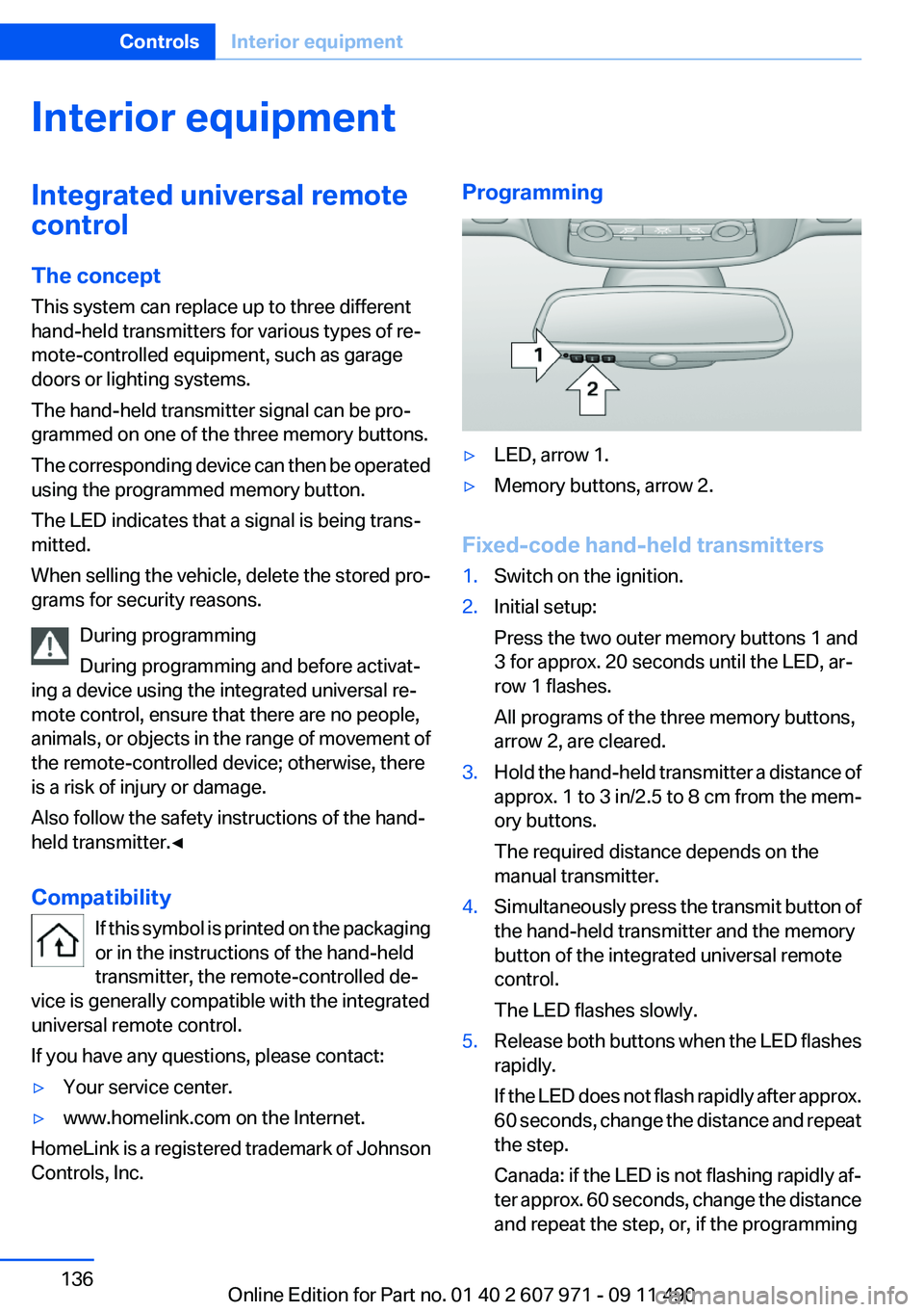
Programming▷LED, arrow 1.▷Memory buttons, arrow 2.
Fixed-code hand-held transmitters
1.Switch on the ignition.2.Initial setup:
Press the two outer memory buttons 1 and
3 for approx. 20 seconds until the LED, ar‐
row 1 flashes.
All programs of the three memory buttons,
arrow 2, are cleared.3.Hold the hand-held transmitter a distance of
approx. 1 to 3 in/2.5 to 8 cm from the mem‐
ory buttons.
The required distance depends on the
manual transmitter.4.Simultaneously press the transmit button of
the hand-held transmitter and the memory
button of the integrated universal remote
control.
The LED flashes slowly.5.Release both buttons when the LED flashes
rapidly.
If the LED does not flash rapidly after approx.
60 seconds, change the distance and repeat
the step.
Canada: if the LED is not flashing rapidly af‐
ter approx. 60 seconds, change the distance
and repeat the step, or, if the programmingSeite 136ControlsInterior equipment136
Online Edition for Part no. 01 40 2 607 971 - 09 11 490
Page 137 of 303
was interrupted by the hand-held transmit‐
ter, hold down the memory button and press
and release the button on the hand-held
transmitter again for 2 seconds.6.To program other hand-held transmitters,
repeat steps 3 to 5.
The device can be operated using the memory
button with the engine running or the ignition
switched on.
Malfunction
If the device cannot be used after repeated at‐
tempts at programming, please check whether
the hand-held transmitter is equipped with an
alternating code system.
To do so:
▷Read the instructions of the hand-held
transmitter.▷Hold down the memory button of the
integrated universal remote control longer.
If the LED of the integrated universal remote
control flashes rapidly for a brief period and then
lights up continuously, the hand-held transmit‐
ter is equipped with an alternating code system.
In this case, program the memory buttons as
described under Alternating-code hand-held
transmitters.
Alternating-code hand-held
transmitters
Please obtain information on synchronizing the
device in the operating manual of the device be‐
ing set up.
Programming will be easier with the aid of a sec‐
ond person.
1.Park the vehicle within range of the remote-
controlled device.2.Program the integrated universal remote
control as described above under Fixed-
code hand-held transmitters.3.Locate the button on the receiver of the de‐
vice to be set, e.g., on the drive.4.Press the button on the receiver of the de‐
vice to be set. You have approx. 30 seconds
for the next step.5.Hold down the programmed memory button
of the integrated universal remote for ap‐
prox. 3 seconds. Repeat this work step, if
necessary, up to three times.
The device can be operated using the memory
button with the engine running or the ignition
switched on.
Reassigning individual programs
1.Switch on the ignition.2.Hold the hand-held transmitter a distance of
approx. 1 to 3 in/2.5 to 8 cm from the mem‐
ory buttons.
The required distance depends on the
manual transmitter.3.Hold down the memory button of the
integrated universal remote control.4.If the LED flashes slowly after approx.
20 seconds, press the transmit button on
the hand-held transmitter.5.Release both buttons when the LED flashes
rapidly.
If the LED does not flash rapidly after approx.
60 seconds, change the distance and repeat
the step.
Canada: if the LED is not flashing rapidly after
approx. 60 seconds, change the distance and
repeat the step, or, if the programming was in‐
terrupted by the hand-held transmitter, hold
down the memory button and press and release
the button on the hand-held transmitter again
for 2 seconds.
Deleting all stored programs
Press the two outer memory buttons for approx.
20 seconds until the LED flashes rapidly.
All stored programs are deleted.
The programs cannot be deleted individually.
Seite 137Interior equipmentControls137
Online Edition for Part no. 01 40 2 607 971 - 09 11 490
Page 138 of 303
Ashtray/cigarette lighter
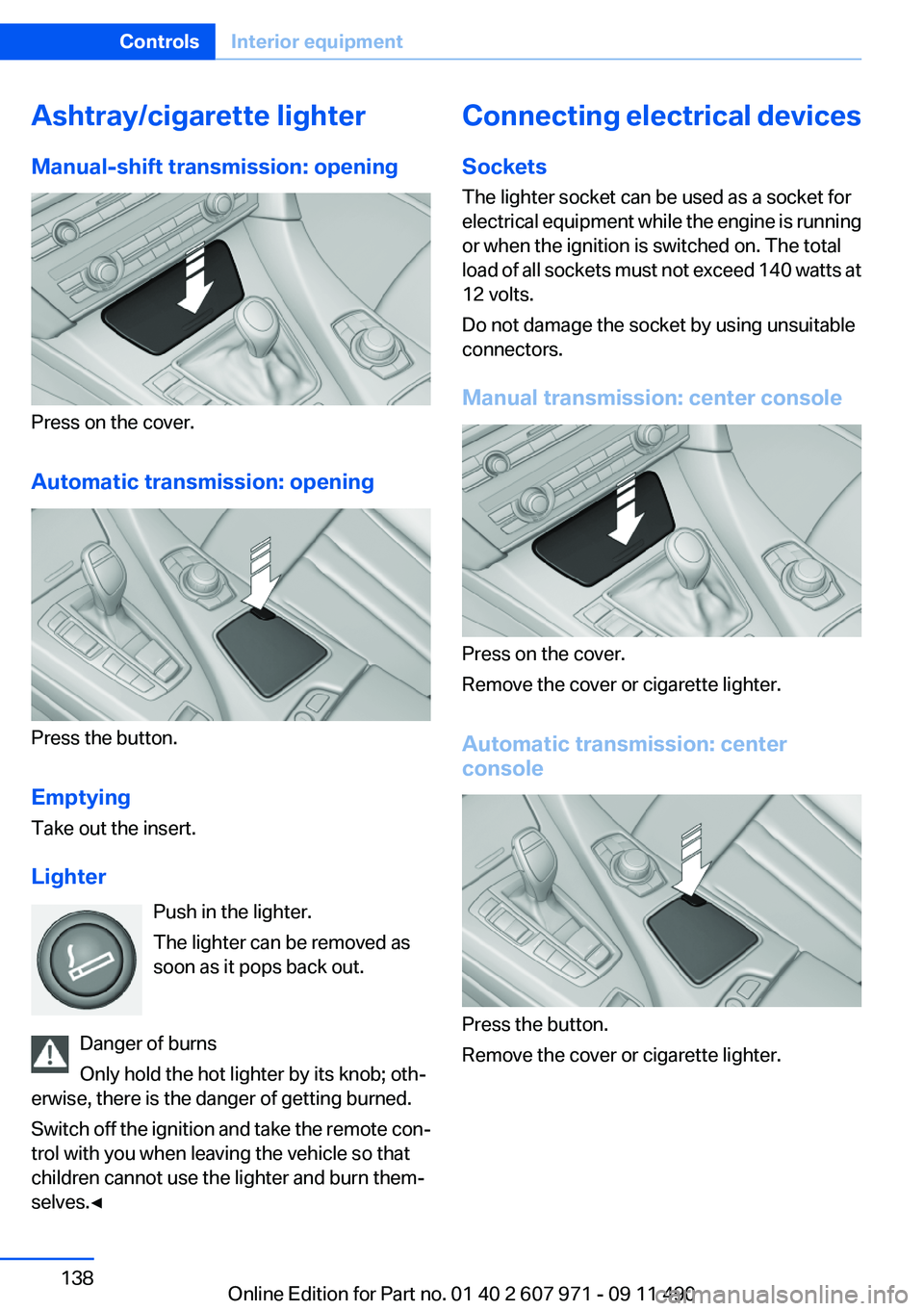
Manual-shift transmission: opening
Press on the cover.
Automatic transmission: opening
Press the button.
Emptying
Take out the insert.
Lighter Push in the lighter.
The lighter can be removed as
soon as it pops back out.
Danger of burns
Only hold the hot lighter by its knob; oth‐
erwise, there is the danger of getting burned.
Switch off the ignition and take the remote con‐
trol with you when leaving the vehicle so that
children cannot use the lighter and burn them‐
selves.◀
Connecting electrical devices
Sockets
The lighter socket can be used as a socket for
electrical equipment while the engine is running
or when the ignition is switched on. The total
load of all sockets must not exceed 140 watts at
12 volts.
Do not damage the socket by using unsuitable
connectors.
Manual transmission: center console
Press on the cover.
Remove the cover or cigarette lighter.
Automatic transmission: center
console
Press the button.
Remove the cover or cigarette lighter.
Seite 138ControlsInterior equipment138
Online Edition for Part no. 01 40 2 607 971 - 09 11 490
Page 166 of 303
3."Options" Open.4."Delete all trips" or "Delete trip"
Open the last trip
1."Navigation"2."Stored trips"3."Last trip"4."Start guidance"
Destination guidance
Starting destination guidance
1."Navigation"2.Make a destination entry, refer to page 158.3."Accept destination"4."Start guidance"▷The route is shown on the Control Display.▷The distance to the destination/intermedi‐
ate destination and the estimated time of ar‐
rival are displayed in the map view.▷The arrow view is shown in the instrument
cluster, in the Head-up Display, and on the
Control Display where appropriate.
Terminating destination guidance
1."Navigation"2."Map"3. "Guidance"4."Stop guidance"
Continuing destination guidance
If the destination was not reached during the last
trip, destination guidance can be resumed.
"Resume guidance"
Route criteria
General information
▷The route calculated can be influenced by
selecting certain criteria.▷The route criteria can be changed when the
destination is entered and during destina‐
tion guidance.▷Road types are part of the navigation data
and are taken into consideration when plan‐
ning a route, e.g., avoid highways.▷The recommended route may differ from the
route you would take based on personal ex‐
perience.▷The settings are stored for the remote con‐
trol currently in use.▷Destination guidance with traffic bulletins,
refer to page 172.
Changing the route criteria
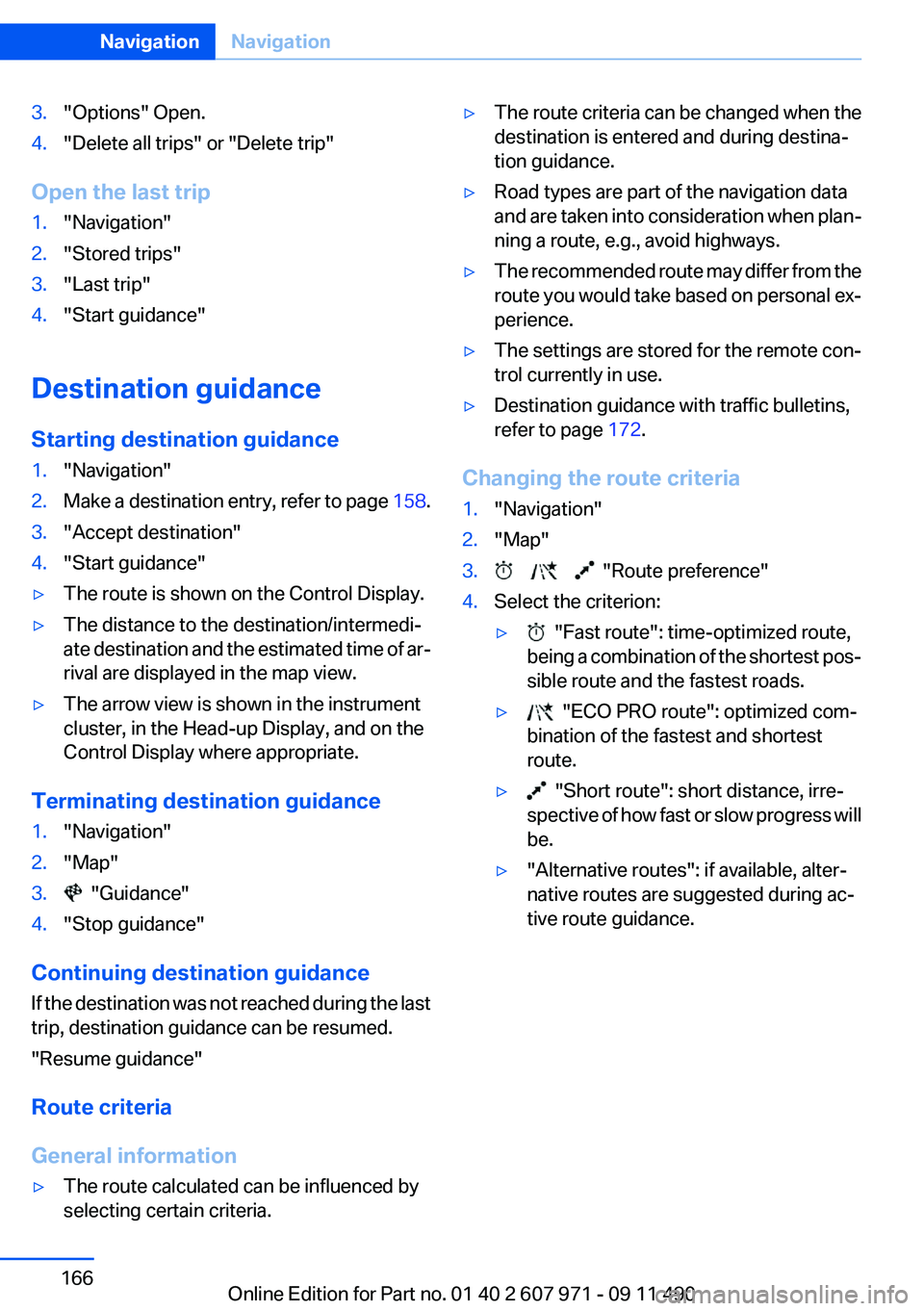
1."Navigation"2."Map"3. "Route preference"4.Select the criterion:▷ "Fast route": time-optimized route,
being a combination of the shortest pos‐
sible route and the fastest roads.▷ "ECO PRO route": optimized com‐
bination of the fastest and shortest
route.▷ "Short route": short distance, irre‐
spective of how fast or slow progress will
be.▷"Alternative routes": if available, alter‐
native routes are suggested during ac‐
tive route guidance.Seite 166NavigationNavigation166
Online Edition for Part no. 01 40 2 607 971 - 09 11 490
Page 168 of 303
Resuming the original route
If the route section should no longer be by‐
passed:1."Navigation"2."Route information"3."New route for:"4."Remove blocking"
Gas station recommendation
The remaining range is calculated, and if nec‐
essary gas stations along the route are dis‐
played.
1."Navigation"2."Route information"3."Recommended refuel"
A list of the gas stations is displayed.4.Highlight a gas station.
The position of the gas station is displayed
on the split screen.5.Select the gas station.6. Select the symbol.7."Start guidance": destination guidance to
the selected gas station is started.
"Add as another destination": the gas sta‐
tion is added to the route.
Switching spoken instructions on/off
The setting is stored for the remote control cur‐
rently in use.
1."Navigation"2."Map"3. "Voice instructions"
Repeating spoken instructions
1."Navigation"2."Map"3. Highlight the symbol.4.Press the controller twice.Volume of spoken instructions
Turn the volume button while giving an instruc‐
tion until the desired volume is set.
Saving the spoken instructions on the
programmable memory buttons
The function for switching the spoken instruc‐
tions on/off can be stored on a programmable
memory button, refer to page 20, for quick ac‐
cess.
Map view
Selecting the map view1."Navigation"2."Map"
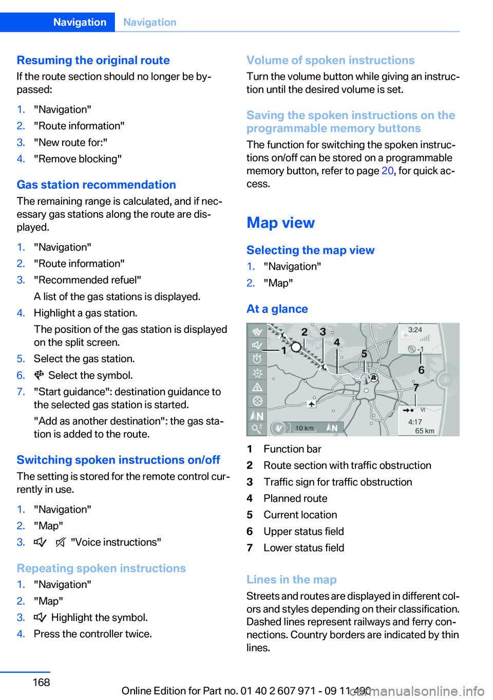
At a glance
1Function bar2Route section with traffic obstruction3Traffic sign for traffic obstruction4Planned route5Current location6Upper status field7Lower status field
Lines in the map
Streets and routes are displayed in different col‐
ors and styles depending on their classification.
Dashed lines represent railways and ferry con‐
nections. Country borders are indicated by thin
lines.
Seite 168NavigationNavigation168
Online Edition for Part no. 01 40 2 607 971 - 09 11 490
Page 169 of 303
Traffic obstructions
Small triangles along the planned route indicate
route sections with traffic obstructions, depend‐
ing on the map scale. The direction of the trian‐
gles indicates the direction of the obstruction.
The traffic signs indicate the significance of the
obstruction.▷Red traffic sign: the obstruction affects the
planned route or direction.▷Gray traffic sign: the obstruction does not
affect the planned route or direction.
Traffic bulletins, refer to page 170.
Planned route
After destination guidance is started, the plan‐
ned route is displayed on the map.
Status fields
Show/hide: press the controller.
▷Upper status field: time, telephone, and en‐
tertainment details.▷Lower status field: symbol for active desti‐
nation guidance, status of traffic bulletins,
time of arrival, and distance to destination.
Function bar
The following functions are available in the func‐
tion bar:
SymbolFunction Start/end destination guidance. Switch spoken instructions on/
off. Change the route criteria. Search for a special destination. Display traffic bulletins. Interactive map. Set the map view. Change the scale.To change to the function bar, move the con‐
troller to the left.
Changing the map section
"Interactive map"
▷To shift the map: move the controller in the
required direction.▷To shift the map diagonally: move the con‐
troller in the required direction and turn it.
Changing the scale
1. Select the symbol.2.To change the scale: turn the controller.
Automatically scaled map scale
In the map view facing north, turn the controller
in any direction until the AUTO scale is dis‐
played. The map shows the entire route be‐
tween the current location and the destination.
Settings for the map view
The settings are stored for the remote control
currently in use.
1."Navigation"2."Map"3."Options" Open.4."Settings"
Set the map view.
▷"Day/night mode"
Select and create the necessary settings
depending on the light conditions.
"Traffic conditions/gray map" active: the
setting is disregarded.▷"Satellite images"
Depending on availability and resolution,
satellite images are displayed in a scale of
approx. 1 mile to 600 miles/2 km to
1,000 km.▷"Perspective view in 3D"Seite 169NavigationNavigation169
Online Edition for Part no. 01 40 2 607 971 - 09 11 490