2012 BMW 550I XDRIVE GRAN TURISMO instrument cluster
[x] Cancel search: instrument clusterPage 80 of 321
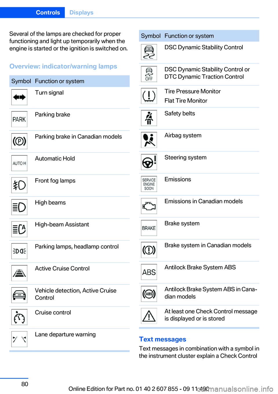
Several of the lamps are checked for proper
functioning and light up temporarily when the
engine is started or the ignition is switched on.
Overview: indicator/warning lampsSymbolFunction or systemTurn signalParking brakeParking brake in Canadian modelsAutomatic HoldFront fog lampsHigh beamsHigh-beam AssistantParking lamps, headlamp controlActive Cruise ControlVehicle detection, Active Cruise
ControlCruise controlLane departure warningSymbolFunction or systemDSC Dynamic Stability ControlDSC Dynamic Stability Control or
DTC Dynamic Traction ControlTire Pressure Monitor
Flat Tire MonitorSafety beltsAirbag systemSteering systemEmissionsEmissions in Canadian modelsBrake systemBrake system in Canadian modelsAntilock Brake System ABSAntilock Brake System ABS in Cana‐
dian modelsAt least one Check Control message
is displayed or is stored
Text messages
Text messages in combination with a symbol in
the instrument cluster explain a Check Control
Seite 80ControlsDisplays80
Online Edition for Part no. 01 40 2 607 855 - 09 11 490
Page 82 of 321
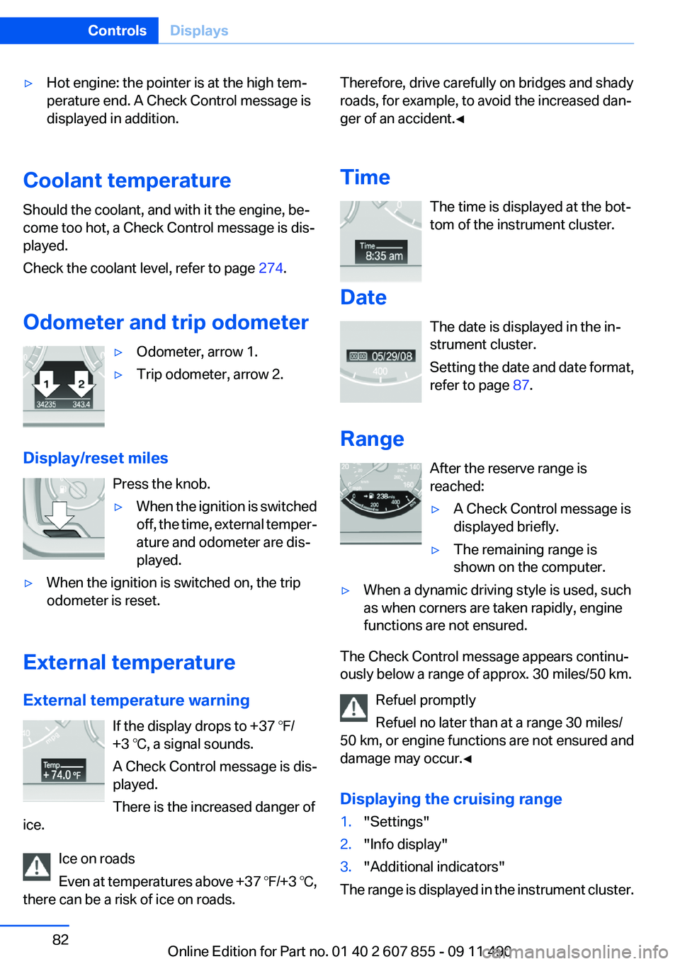
▷Hot engine: the pointer is at the high tem‐
perature end. A Check Control message is
displayed in addition.
Coolant temperature
Should the coolant, and with it the engine, be‐
come too hot, a Check Control message is dis‐
played.
Check the coolant level, refer to page 274.
Odometer and trip odometer
▷Odometer, arrow 1.▷Trip odometer, arrow 2.
Display/reset miles Press the knob.
▷When the ignition is switched
off, the time, external temper‐
ature and odometer are dis‐
played.▷When the ignition is switched on, the trip
odometer is reset.
External temperature
External temperature warning If the display drops to +37 ℉/
+3 ℃, a signal sounds.
A Check Control message is dis‐
played.
There is the increased danger of
ice.
Ice on roads
Even at temperatures above +37 ℉/+3 ℃,
there can be a risk of ice on roads.
Therefore, drive carefully on bridges and shady
roads, for example, to avoid the increased dan‐
ger of an accident.◀
Time The time is displayed at the bot‐
tom of the instrument cluster.
Date The date is displayed in the in‐
strument cluster.
Setting the date and date format,
refer to page 87.
Range After the reserve range is
reached:▷A Check Control message is
displayed briefly.▷The remaining range is
shown on the computer.▷When a dynamic driving style is used, such
as when corners are taken rapidly, engine
functions are not ensured.
The Check Control message appears continu‐
ously below a range of approx. 30 miles/50 km.
Refuel promptly
Refuel no later than at a range 30 miles/
50 km, or engine functions are not ensured and
damage may occur.◀
Displaying the cruising range
1."Settings"2."Info display"3."Additional indicators"
The range is displayed in the instrument cluster.
Seite 82ControlsDisplays82
Online Edition for Part no. 01 40 2 607 855 - 09 11 490
Page 83 of 321
Range when destination guidance is
activated in the navigation system
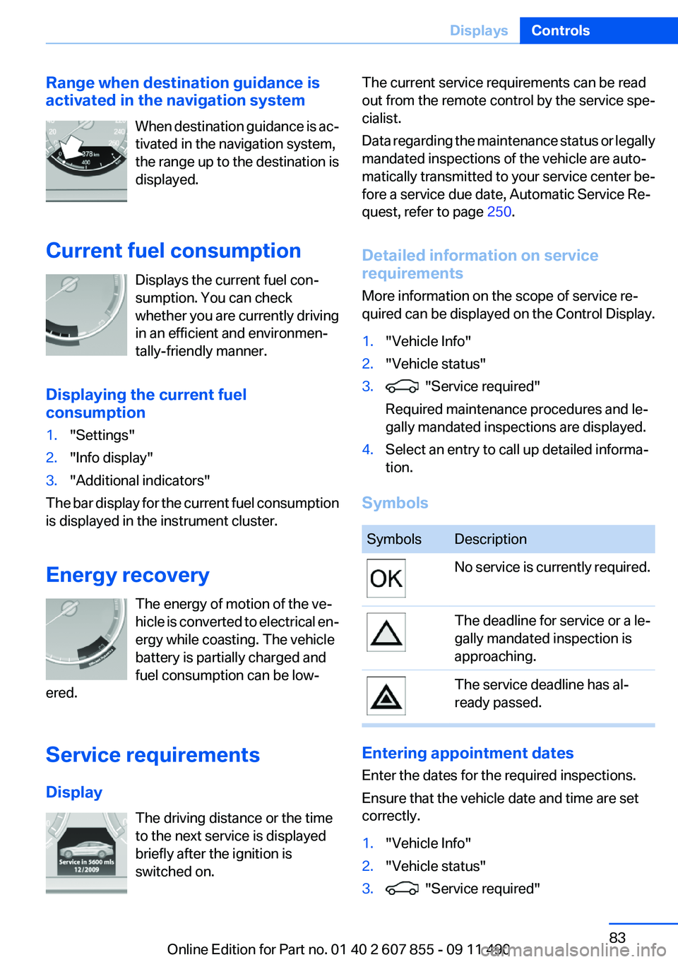
When destination guidance is ac‐
tivated in the navigation system,
the range up to the destination is
displayed.
Current fuel consumption Displays the current fuel con‐
sumption. You can check
whether you are currently driving
in an efficient and environmen‐
tally-friendly manner.
Displaying the current fuel
consumption1."Settings"2."Info display"3."Additional indicators"
The bar display for the current fuel consumption
is displayed in the instrument cluster.
Energy recovery The energy of motion of the ve‐
hicle is converted to electrical en‐
ergy while coasting. The vehicle
battery is partially charged and
fuel consumption can be low‐
ered.
Service requirements
Display The driving distance or the time
to the next service is displayed
briefly after the ignition is
switched on.
The current service requirements can be read
out from the remote control by the service spe‐
cialist.
Data regarding the maintenance status or legally
mandated inspections of the vehicle are auto‐
matically transmitted to your service center be‐
fore a service due date, Automatic Service Re‐
quest, refer to page 250.
Detailed information on service
requirements
More information on the scope of service re‐
quired can be displayed on the Control Display.1."Vehicle Info"2."Vehicle status"3. "Service required"
Required maintenance procedures and le‐
gally mandated inspections are displayed.4.Select an entry to call up detailed informa‐
tion.
Symbols
SymbolsDescriptionNo service is currently required.The deadline for service or a le‐
gally mandated inspection is
approaching.The service deadline has al‐
ready passed.
Entering appointment dates
Enter the dates for the required inspections.
Ensure that the vehicle date and time are set
correctly.
1."Vehicle Info"2."Vehicle status"3. "Service required"Seite 83DisplaysControls83
Online Edition for Part no. 01 40 2 607 855 - 09 11 490
Page 84 of 321
4."§ Vehicle inspection"5."Date:"6.Create the settings.7.Confirm.
The entered date is stored.
Automatic Service Request
Data regarding the maintenance status or legally
mandated inspections of the vehicle are auto‐
matically transmitted to your service center be‐
fore a service due date.
You can check when your service center was
notified.
1."Vehicle Info"2."Vehicle status"3.Open "Options".4."Last Service Request"
Selection lists in the
instrument cluster
The concept
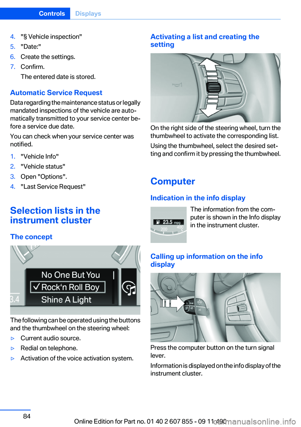
The following can be operated using the buttons
and the thumbwheel on the steering wheel:
▷Current audio source.▷Redial on telephone.▷Activation of the voice activation system.Activating a list and creating the
setting
On the right side of the steering wheel, turn the
thumbwheel to activate the corresponding list.
Using the thumbwheel, select the desired set‐
ting and confirm it by pressing the thumbwheel.
Computer
Indication in the info display The information from the com‐
puter is shown in the Info display
in the instrument cluster.
Calling up information on the info
display
Press the computer button on the turn signal
lever.
Information is displayed on the info display of the
instrument cluster.
Seite 84ControlsDisplays84
Online Edition for Part no. 01 40 2 607 855 - 09 11 490
Page 85 of 321
Information at a glance
Repeatedly pressing the button on the turn sig‐
nal lever calls up the following information on the
info display:▷Range.▷Average fuel consumption.▷Average speed.▷Date.▷Time of arrival
When destination guidance is activated in
the navigation system.▷Distance to destination
When destination guidance is activated in
the navigation system.▷Arrow view of navigation system
When destination guidance is activated in
the navigation system.
Adjusting the info display
You can select what information from the com‐
puter is to be displayed on the info display of the
instrument cluster.
1."Settings"2."Info display"3.Select the desired displays.
Information in detail
Range
Displays the estimated cruising range available
with the remaining fuel.
It is calculated based on your driving style over
the last 20 miles/30 km. If there is only enough
fuel left for less than 45 miles/80 km, the color
of the display changes.
Average fuel consumption
This is calculated for the period during which the
engine is running.
The average fuel consumption is calculated on
the basis of various distances.
Average speed
Periods in which the vehicle is parked with the
engine manually stopped do not enter into the
calculation of the average speed.
Resetting average values
Press and hold the computer button on the turn
signal lever.
Distance to destination
The distance remaining to the destination is dis‐
played if a destination is entered in the naviga‐
tion system before the trip is started.
The distance to the destination is adopted au‐
tomatically.
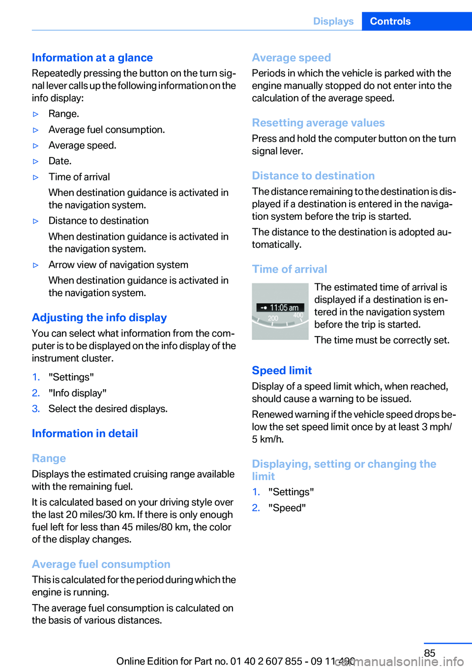
Time of arrival The estimated time of arrival is
displayed if a destination is en‐
tered in the navigation system
before the trip is started.
The time must be correctly set.
Speed limit
Display of a speed limit which, when reached,
should cause a warning to be issued.
Renewed warning if the vehicle speed drops be‐
low the set speed limit once by at least 3 mph/
5 km/h.
Displaying, setting or changing the
limit1."Settings"2."Speed"Seite 85DisplaysControls85
Online Edition for Part no. 01 40 2 607 855 - 09 11 490
Page 90 of 321
Headlamp courtesy delay feature
The low beams stay lit for a short while after the
ignition is switched off, if the lamps are switched
off and the headlamp flasher is switched on.
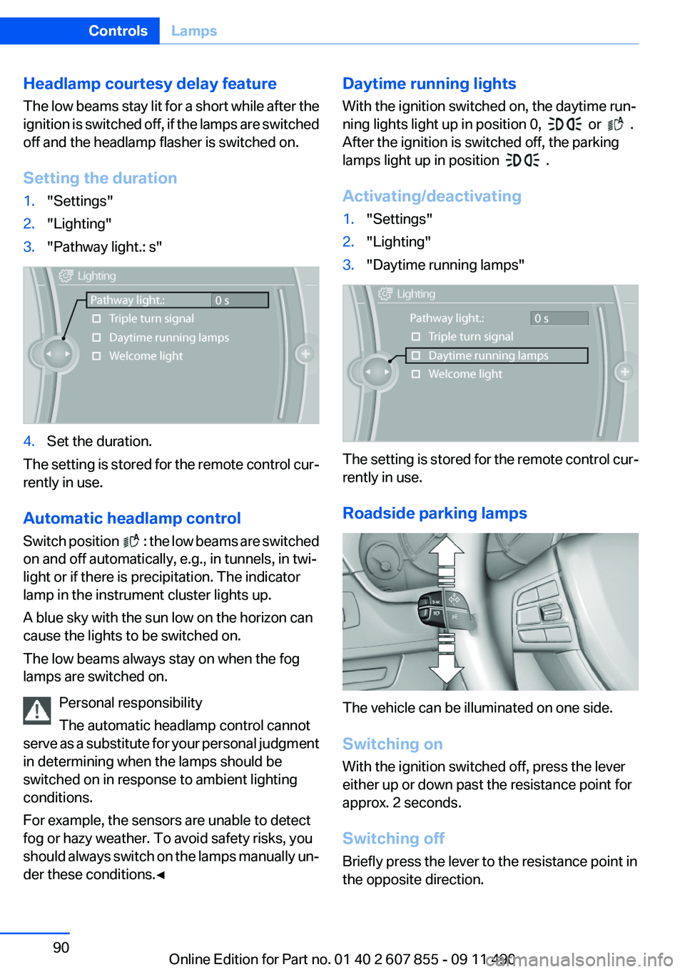
Setting the duration1."Settings"2."Lighting"3."Pathway light.: s"4.Set the duration.
The setting is stored for the remote control cur‐
rently in use.
Automatic headlamp control
Switch position
: the low beams are switched
on and off automatically, e.g., in tunnels, in twi‐
light or if there is precipitation. The indicator
lamp in the instrument cluster lights up.
A blue sky with the sun low on the horizon can
cause the lights to be switched on.
The low beams always stay on when the fog
lamps are switched on.
Personal responsibility
The automatic headlamp control cannot
serve as a substitute for your personal judgment
in determining when the lamps should be
switched on in response to ambient lighting
conditions.
For example, the sensors are unable to detect
fog or hazy weather. To avoid safety risks, you
should always switch on the lamps manually un‐
der these conditions.◀
Daytime running lights
With the ignition switched on, the daytime run‐
ning lights light up in position 0,
or .
After the ignition is switched off, the parking
lamps light up in position
.
Activating/deactivating
1."Settings"2."Lighting"3."Daytime running lamps"
The setting is stored for the remote control cur‐
rently in use.
Roadside parking lamps
The vehicle can be illuminated on one side.
Switching on
With the ignition switched off, press the lever
either up or down past the resistance point for
approx. 2 seconds.
Switching off
Briefly press the lever to the resistance point in
the opposite direction.
Seite 90ControlsLamps90
Online Edition for Part no. 01 40 2 607 855 - 09 11 490
Page 91 of 321
Adaptive light control
The concept
Adaptive light control is a variable headlamp
control system that enables dynamic illumina‐
tion of the road surface.
Depending on the steering angle and other pa‐
rameters, the light from the headlamp follows
the course of the road.
In tight curves, e.g., on mountainous roads or
when turning, an additional, corner-illuminating
lamp is switched on that lights up the inside of
the curve when the vehicle is moving below a
certain speed.
Activating
Switch position
with the ignition switched
on.
The turning lamps are automatically switched
on depending on the steering angle or the use
of turn signals.
To avoid blinding oncoming traffic, the Adaptive
Light Control directs light towards the front pas‐
senger side when the vehicle is at a standstill.
When driving in reverse, only the turning lamp is
active.
Self-leveling headlights
The self-leveling headlights feature adapts the
light distribution to the contours of the road.
The light distribution is lowered on hilltops to
avoid blinding oncoming traffic and tilted in de‐
pressions to increase visibility.
Malfunction
A Check Control message is displayed.
Adaptive light control is malfunctioning or has
failed. Have the system checked as soon as pos‐
sible.
High-beam Assistant
The concept
When the low beams are switched on, this sys‐
tem automatically switches the high beams on
and off. The procedure is controlled by a sensor
on the front of the interior rearview mirror. The
assistant ensures that the high beams are
switched on whenever the traffic situation al‐
lows. The driver can intervene at any time and
switch the high beams on and off as usual.
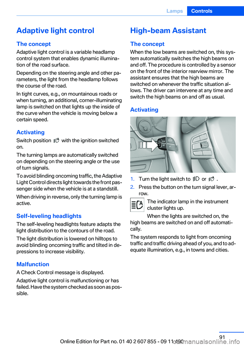
Activating1.Turn the light switch to or .2.Press the button on the turn signal lever, ar‐
row.
The indicator lamp in the instrument
cluster lights up.
When the lights are switched on, the
high beams are switched on and off automati‐
cally.
The system responds to light from oncoming
traffic and traffic driving ahead of you, and to ad‐
equate illumination, e.g., in towns and cities.
Seite 91LampsControls91
Online Edition for Part no. 01 40 2 607 855 - 09 11 490
Page 95 of 321
Protective action
Airbags are not triggered in every impact situa‐
tion, e.g., in less severe accidents or rear-end
collisions.
Information on how to ensure the optimal
protective effect of the airbags▷Keep at a distance from the airbags.▷Always grasp the steering wheel on the
steering wheel rim, holding your hands at
the 3 o'clock and 9 o'clock positions, to keep
the danger of injury to your hands or arms as
low as possible if the airbag is triggered.▷There should be no people, animals, or ob‐
jects between an airbag and a person.▷Do not use the cover of the front airbag on
the front passenger side as a storage area.▷Keep the dashboard and window on the
front passenger side clear, i.e., do not cover
with adhesive labels or coverings, and do not
attach holders such as for navigation instru‐
ments and mobile phones.▷Make sure that the front passenger is sitting
correctly, i.e., keeps his or her feet and legs
in the footwell; otherwise, leg injuries can
occur if the front airbag is triggered.▷Do not place slip covers, seat cushions or
other objects on the front passenger seat
that are not approved specifically for seats
with integrated side airbags.▷Do not hang pieces of clothing, such as jack‐
ets, over the backrests.▷Make sure that occupants keep their heads
away from the side airbag and do not rest
against the head airbag; otherwise, injuries
can occur if the airbags are triggered.▷Do not remove the airbag restraint system.▷Do not remove the steering wheel.▷Do not apply adhesive materials to the air‐
bag cover panels, cover them or modify
them in any way.▷Never modify either the individual compo‐
nents or the wiring in the airbag system. This
also applies to steering wheel covers, the
dashboard, the seats, the roof pillars and the
sides of the headliner.◀
Even when all instructions are followed closely,
injury from contact with the airbags cannot be
ruled out in certain situations.
The ignition and inflation noise may lead to
short-term and, in most cases, temporary hear‐
ing impairment in sensitive individuals.
In the case of a malfunction, deactivation
and after triggering of the airbags
Do not touch the individual components imme‐
diately after the system has been triggered; oth‐
erwise, there is the danger of burns.
Only have the airbags checked, repaired or dis‐
mantled and the airbag generator scrapped by
your service center or a workshop that has the
necessary authorization for handling explosives.
Non-professional attempts to service the sys‐
tem could lead to failure in an emergency or un‐
desired triggering of the airbag, either of which
could result in injury.◀
Warnings and information on the airbags are
also found on the sun visors.
Functional readiness of the airbag
system
When the ignition is switch on, the warn‐
ing lamp in the instrument cluster lights
up briefly and thereby indicates the op‐
erational readiness of the entire airbag system
and the belt tensioner.
Airbag system malfunctioning
▷Warning lamp does not come on when the
ignition is turned on.▷The warning lamp lights up continuously.Seite 95SafetyControls95
Online Edition for Part no. 01 40 2 607 855 - 09 11 490