2012 BMW 335I radio
[x] Cancel search: radioPage 67 of 325

Otherwise, there is the danger of fire and a risk
to personal safety if the fluid is spilled.◀
All washer nozzles are supplied from one reser‐
voir.
Fill with water and – if required – with a washer
antifreeze, according to the manufacturer's rec‐
ommendations.
Mix the washer fluid before adding to maintain
the correct mixing ratio.
Manual transmission
Shifting Shifting into 5th or 6th gear
When shifting into 5th or 6th gear, push
the gearshift lever to the right; otherwise inad‐
vertent shifting into the 3rd or 4th gear could
lead to engine damage.◀
Reverse gear
Select only when the vehicle is stationary. When
the gearshift lever is pressed to the left, a slight
resistance needs to be overcome.
Automatic transmission with
Steptronic
Transmission positions
D Drive, automatic position
Position for normal vehicle operation. All for‐
ward gears are available.
R is Reverse
Select only when the vehicle is stationary.
N is Neutral
Use in automatic car washes, for example. The
vehicle can roll.
When the ignition is switched off, refer to
page 59, position P is engaged automatically.
P Park
Select only when the vehicle is stationary. The
drive wheels are blocked.
P is engaged automatically:▷After the engine is switched off, if the car is
in radio ready state, refer to page 60, or if the
ignition is switched off, refer to page 59, and
if position R or D is engaged.▷With the ignition is off, if position N is en‐
gaged.▷If the safety belt is unbuckled, the driver's
door is opened, and the brake pedal is not
pressed while the vehicle is stationary and
transmission position R or D is engaged.
Before exiting the vehicle, make sure that posi‐
tion P of the automatic transmission is engaged.
Otherwise, the vehicle may begin to roll.
Kickdown
Kickdown is used to achieve maximum driving
performance. Press on the gas pedal beyond the
resistance point at the full throttle position.
Engaging the transmission position
▷Transmission position P can only be disen‐
gaged if the engine is running and the brake
pedal is pressed.▷With the vehicle stationary, press on the
brake pedal before shifting out of P or N;
otherwise, the shift command will not be
executed: shift lock.Seite 67DrivingControls67
Online Edition for Part no. 01 40 2 608 633 - 11 09 490
Page 73 of 325

Overview, instrument cluster with enhanced features1Time 76
External temperature 76
Date 76
Selection list, e.g., radio 80
Speed limit detection 79
Computer 81
Miles/trip miles 76Navigation display 1682Energy recovery 77
Transmission display 69
Current fuel consumption 77
ECO PRO 1633Messages, e.g. Check Control 73
Service requirements 77Check Control
The concept
The Check Control system monitors functions
in the vehicle and notifies you of malfunctions in
the monitored systems.
A Check Control message is displayed as a
combination of indicator or warning lamps and
text messages in the instrument cluster and in
the Head-up Display.
In addition, an acoustic signal may be output and
a text message may appear on the Control Dis‐
play.Indicator/warning lamps
The indicator and warning lamps can light up in
a variety of combinations and colors.
Seite 73DisplaysControls73
Online Edition for Part no. 01 40 2 608 633 - 11 09 490
Page 94 of 325

senger airbags lights up. This indicates that the
child seat has been detected and the front pas‐
senger airbags are not activated.
Strength of the driver's and front
passenger airbag
The strength with which the driver's and front
passenger airbags are triggered depends on the
position of the driver's and front passenger
seats.
To maintain the accuracy of this function over
the long-term, calibrate the front seats when a
corresponding message appears on the Control
Display.
Calibrating the front seats
A corresponding message appears on the Con‐
trol Display.1.Move the respective seat forward all the
way.2.Move the respective seat forward again. It
moves forward briefly.3.Readjust the seat to the desired position.
The calibration procedure is completed when
the message on the Control Display disappears.
If the message continues to be displayed, repeat
the calibration.
If the message does not disappear after a repeat
calibration, have the system checked as soon as
possible.
Unobstructed area of movement
Ensure that the area of movement of the
seats is unobstructed to avoid personal injury or
damage to objects.◀
Tire Pressure Monitor TPM
The concept
The tire inflation pressure is measured in the
four mounted tires. The system notifies you if
there is a significant loss of pressure in one or
more tires.
Functional requirements
The system must have been reset when the in‐
flation pressure was correct; otherwise, reliable
signaling of a flat tire is not ensured. Always use
wheels with TPM electronics to ensure that the
system will operate properly. Reset the system
after each correction of the tire inflation pres‐
sure and after every tire or wheel change.
System limits Sudden tire damage
Sudden serious tire damage caused by
external influences cannot be indicated in ad‐
vance.◀
The system does not operate correctly if it has
not been reset. For example, a flat tire may be
indicated despite correct tire inflation pres‐
sures.
The system is inactive and cannot indicate a flat
tire:▷For a mounted wheel without TPM electron‐
ics.▷When the TPM is disturbed by other sys‐
tems or devices with the same radio fre‐
quency.
Status display
The current status of the Tire Pressure Monitor
TPM can be displayed on the Control Display,
e.g., whether or not the TPM is active.
1."Vehicle Info"2."Vehicle status"3. "Tire Pressure Monitor - TPM"
The status is displayed.
Status display
The tire and system status is indicated by the
color of the tires.
Seite 94ControlsSafety94
Online Edition for Part no. 01 40 2 608 633 - 11 09 490
Page 95 of 325

A change in the tire inflation pressure during
driving is taken into account.
A correction is only necessary if this is indicated
by the TPM
Wheels, green
The tire inflation pressure is equal to the target
state.
One wheel is yellow
A flat tire or major drop in inflation pressure in
the indicated tire.
All wheels are yellow▷A flat tire or major drop in inflation pressure
in several tires.▷The system was not reset after a wheel
change and thus warns based on the infla‐
tion pressures initialized last.▷A flat tire in one or more tires while the sys‐
tem is being reset.
Wheels, gray
The system cannot detect a flat tire. Reasons for
this may be:
▷TPM is being reset.▷Disturbance by systems or devices with the
same radio frequency.▷Malfunction.
Resetting the system
Reset the system after each correction of the
tire inflation pressure and after every tire or
wheel change.
1."Vehicle Info"2."Vehicle status"3. "Reset"4.Start the engine - do not drive away.5.Reset the tire pressure using "Reset".6.Drive away.The tires are shown in gray and "Resetting
TPM..." is displayed.
After driving for a few minutes, the set tire infla‐
tion pressures are applied as set values. The re‐
setting process is completed automatically dur‐
ing driving. The tires are shown in green and
"TPM active" is shown on the Control Display.
The trip can be interrupted at any time. If you
drive away again, the process resumes auto‐
matically.
If a flat tire is detected during a reset, all tires are
displayed in yellow.
Low tire pressure message The yellow warning lamp lights up. A
Check Control message is displayed.▷There is a flat tire or a major loss in
tire inflation pressure.▷The system was not reset after a wheel
change and thus warns based on the infla‐
tion pressures initialized last.1.Reduce your speed and stop cautiously.
Avoid sudden braking and steering maneu‐
vers.2.Check whether the vehicle is fitted with reg‐
ular tires or run-flat tires.
Run-flat tires, refer to page 271, are labeled
with a circular symbol containing the letters
RSC marked on the tire sidewall.
Do not continue driving without run-flat
tires
Do not continue driving if the vehicle is not
equipped with run-flat tires; continued driving
may result in serious accidents.◀
When a low inflation pressure is indicated, DSC
Dynamic Stability Control is switched on if nec‐
essary.
Actions in the event of a flat tire
Normal tires
1.Identify the damaged tire.Seite 95SafetyControls95
Online Edition for Part no. 01 40 2 608 633 - 11 09 490
Page 97 of 325

▷A wheel without TPM electronics is fitted:
have the service center check it if necessary.▷Malfunction: have the system checked by
your service center.▷TPM could not be fully reset. Reset the sys‐
tem again.▷Disturbance by systems or devices with the
same radio frequency: after leaving the area
of the disturbance, the system automatically
becomes active again.
Declaration according to NHTSA/
FMVSS 138 Tire Pressure Monitoring
System
Each tire, including the spare (if provided)
should be checked monthly when cold and in‐
flated to the inflation pressure recommended by
the vehicle manufacturer on the vehicle placard
or tire inflation pressure label. (If your vehicle has
tires of a different size than the size indicated on
the vehicle placard or tire inflation pressure la‐
bel, you should determine the proper tire infla‐
tion pressure for those tires.) As an added safety
feature, your vehicle has been equipped with a
tire pressure monitoring system (TPMS) that il‐
luminates a low tire pressure telltale when one
or more of your tires is significantly under-in‐
flated. Accordingly, when the low tire pressure
telltale illuminates, you should stop and check
your tires as soon as possible, and inflate them
to the proper pressure. Driving on a significantly
under-inflated tire causes the tire to overheat
and can lead to tire failure. Under-inflation also
reduces fuel efficiency and tire tread life, and
may affect the vehicle's handling and stopping
ability. Please note that the TPMS is not a sub‐
stitute for proper tire maintenance, and it is the
driver's responsibility to maintain correct tire
pressure, even if under-inflation has not reached
the level to trigger illumination of the TPMS low
tire pressure telltale. Your vehicle has also been
equipped with a TPMS malfunction indicator to
indicate when the system is not operating prop‐
erly. The TPMS malfunction indicator is com‐
bined with the low tire pressure telltale. When
the system detects a malfunction, the telltale will
flash for approximately one minute and then re‐
main continuously illuminated. This sequence
will continue upon subsequent vehicle start-ups
as long as the malfunction exists. When the mal‐
function indicator is illuminated, the system may
not be able to detect or signal low tire pressure
as intended. TPMS malfunctions may occur for
a variety of reasons, including the installation of
replacement or alternate tires or wheels on the
vehicle that prevent the TPMS from functioning
properly. Always check the TPMS malfunction
telltale after replacing one or more tires or
wheels on your vehicle to ensure that the re‐
placement or alternate tires and wheels allow
the TPMS to continue to function properly.
FTM Flat Tire Monitor
The concept
The system does not measure the actual infla‐
tion pressure in the tires.
It detects a pressure loss in a tire by comparing
the rotational speeds of the individual wheels
while moving.
In the event of a pressure loss, the diameter and
therefore the rotational speed of the corre‐
sponding wheel change. This is detected and
reported as a flat tire.
Functional requirements
The system must have been initialized when the
tire inflation pressure was correct; otherwise,
reliable signaling of a flat tire is not ensured. In‐
itialize the system after each correction of the
tire inflation pressure and after every tire or
wheel change.
System limits Sudden tire damage
Sudden serious tire damage caused by
external influences cannot be indicated in ad‐
vance.◀Seite 97SafetyControls97
Online Edition for Part no. 01 40 2 608 633 - 11 09 490
Page 115 of 325

▷this device must accept any interference re‐
ceived, including interference that may
cause undesired operation.
Any unauthorized modifications or changes to
these devices could void the user's authority to
operate this equipment.
Note
To reduce electromagnetic effects, please use
properly.
The standard SAR value is 2.0 W/kg; the tested
value of this product is 0.751 W/kg.
NCC declaration:
1.Companies or persons without authoriza‐
tion should not change the frequency, in‐
crease the power, or change the character‐
istics or functions of the original design of
low-power radio frequency devices with
type approval.2.Low-power radio frequency devices should
not impair legal communication or flight
safety. If this type of impairment is detected,
the device should be switched off immedi‐
ately. In this case, please contact the man‐
ufacturer and only use the product after the
problem has been corrected.3.The "legal communication" specified above
refers to communication in accordance with
telecommunication regulations. Low-power
devices should withstand interference from
legal communication and ISM devices.
Collision warning
The concept
If the vehicle does not include Active Cruise
Control with Stop & Go, the collision warning is
controlled via the camera in the base of the in‐
terior rearview mirror.
The system issues a two-phase warning of a
danger of collision at speeds above approx.
10 mph/15 km/h. The time of these warnings
may vary depending on the current driving sit‐
uation.
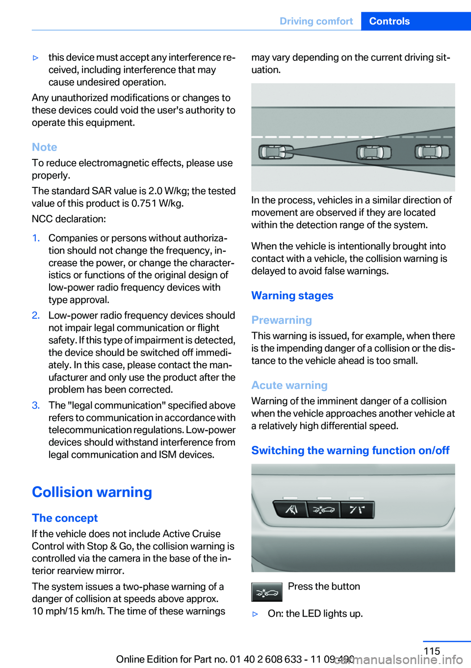
In the process, vehicles in a similar direction of
movement are observed if they are located
within the detection range of the system.
When the vehicle is intentionally brought into
contact with a vehicle, the collision warning is
delayed to avoid false warnings.
Warning stages
Prewarning
This warning is issued, for example, when there
is the impending danger of a collision or the dis‐
tance to the vehicle ahead is too small.
Acute warning
Warning of the imminent danger of a collision
when the vehicle approaches another vehicle at
a relatively high differential speed.
Switching the warning function on/off
Press the button
▷On: the LED lights up.Seite 115Driving comfortControls115
Online Edition for Part no. 01 40 2 608 633 - 11 09 490
Page 180 of 325

"Traffic conditions/gray map" active: the
setting is disregarded.▷"Satellite images"
Depending on availability and resolution,
satellite images are displayed in a scale of
approx. 1 mile to 600 miles/2 km to
1,000 km.▷"Perspective view in 3D"
Prominent areas that are contained in the
navigation data are displayed on the map in
3D.▷"Traffic conditions/gray map"
The map is optimized for displaying traffic
bulletins, refer to page 180. Symbols for the
special destinations are no longer displayed.
Map view for split screen
The map view can be selected for the split
screen independently from the main screen.
1."Options" Open.2."Split screen"3.Move the controller to the right repeatedly
until the split screen is selected.4.Select "Split screen content" or the scale.5.Select the map view.▷"Arrow display"▷"Map facing north"▷"Map direction of travel"▷"Map view with perspective"▷"Position"▷"Exit ramp view": selected blind drive‐
ways are displayed three dimensionally.
Setting in some cases will affect the dis‐
play in the Head-Up Display.▷"Traffic conditions/gray map"6.To change the scale: select the split screen
and turn the controller.Traffic bulletins
At a glance
General information▷Display the traffic bulletins from radio sta‐
tions that broadcast the TI Traffic Informa‐
tion of a traffic information service. Informa‐
tion on traffic obstructions and hazards is
updated continuously.
Certain BMW models equipped with navi‐
gation have the capability to display real-
time traffic information. If your system has
this capability the following additional terms
and conditions apply:
An End-User shall no longer have the right
to use the Traffic Data in the event that the
End-User is in material breach of the terms
and conditions contained herein.
A. Total Traffic Network, a division of Clear
Channel Broadcasting, Inc. (“Total Traffic
Network”) holds the rights to the traffic in‐
cident data and RDS-TMC network through
which it is delivered. You may not modify,
copy, scan or use any other method to re‐
produce, duplicate, republish, transmit or
distribute in any way any portion of traffic in‐
cident data. You agree to indemnify, defend
and hold harmless BMW of North America,
LLC. (“BMW NA”) and Total Traffic Net‐
work, Inrix, Inc (and their affiliates) against
any and all claims, damages, costs or other
expenses that arise directly or indirectly out
of (a) your unauthorized use of the traffic in‐
cident data or the RDS-TMC network, (b)
your violation of this directive and/or (c) any
unauthorized or unlawful activities by you in
connection herewith.
B. Total Traffic Network traffic data is infor‐
mational only. User assumes all risk of use.
Total Traffic Network, BMW NA, and their
suppliers make no representations about
content, traffic and road conditions, route
usability, or speed.Seite 180NavigationNavigation system180
Online Edition for Part no. 01 40 2 608 633 - 11 09 490
Page 187 of 325

Entertainment
The chapter helps assure your enjoyment when
receiving radio and television stations and playing CDs, DVDs and tracks from the music collection.Online Edition for Part no. 01 40 2 608 633 - 11 09 490