2012 BMW 335I Sport
[x] Cancel search: SportPage 57 of 325
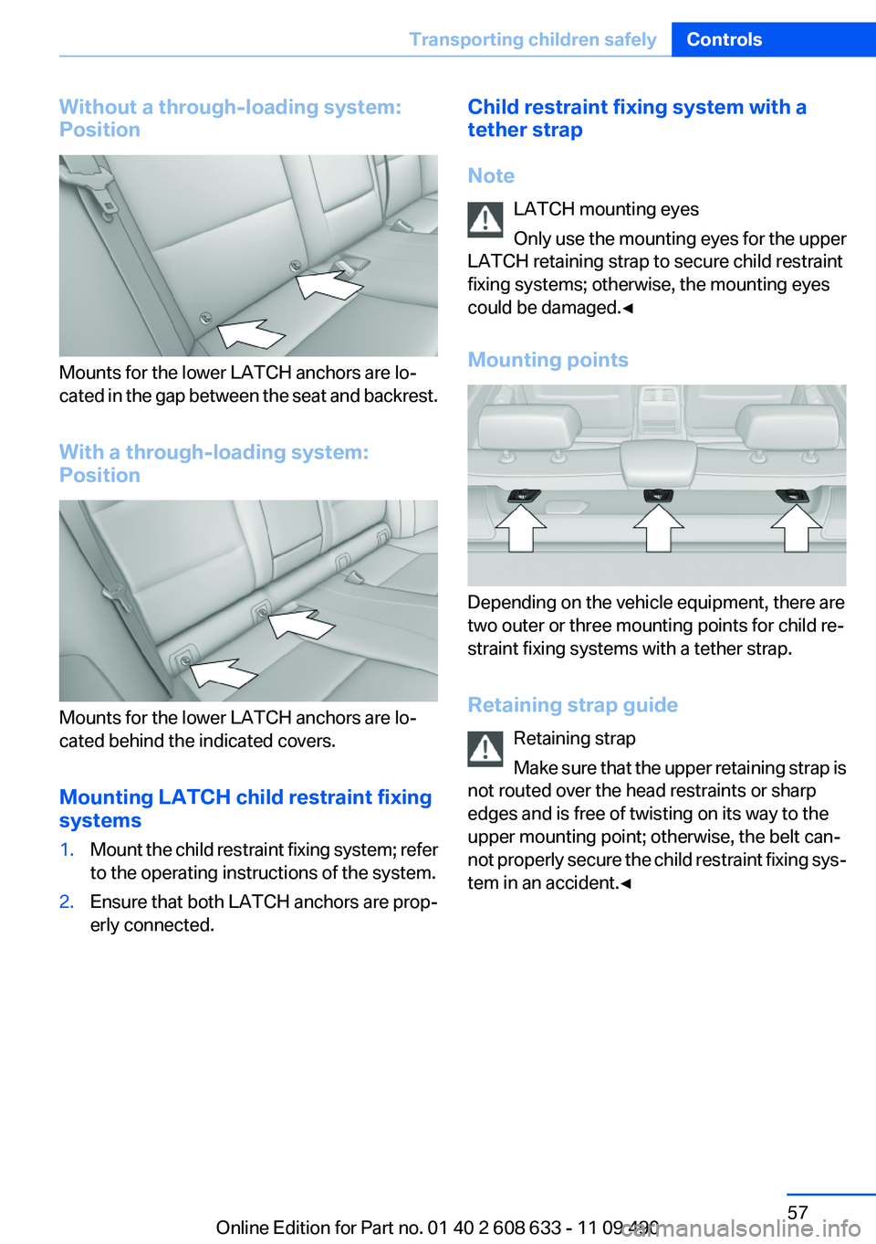
Without a through-loading system:
Position
Mounts for the lower LATCH anchors are lo‐
cated in the gap between the seat and backrest.
With a through-loading system:
Position
Mounts for the lower LATCH anchors are lo‐
cated behind the indicated covers.
Mounting LATCH child restraint fixing
systems
1.Mount the child restraint fixing system; refer
to the operating instructions of the system.2.Ensure that both LATCH anchors are prop‐
erly connected.Child restraint fixing system with a
tether strap
Note LATCH mounting eyes
Only use the mounting eyes for the upper
LATCH retaining strap to secure child restraint
fixing systems; otherwise, the mounting eyes
could be damaged.◀
Mounting points
Depending on the vehicle equipment, there are
two outer or three mounting points for child re‐
straint fixing systems with a tether strap.
Retaining strap guide Retaining strap
Make sure that the upper retaining strap is
not routed over the head restraints or sharp
edges and is free of twisting on its way to the
upper mounting point; otherwise, the belt can‐
not properly secure the child restraint fixing sys‐
tem in an accident.◀
Seite 57Transporting children safelyControls57
Online Edition for Part no. 01 40 2 608 633 - 11 09 490
Page 58 of 325
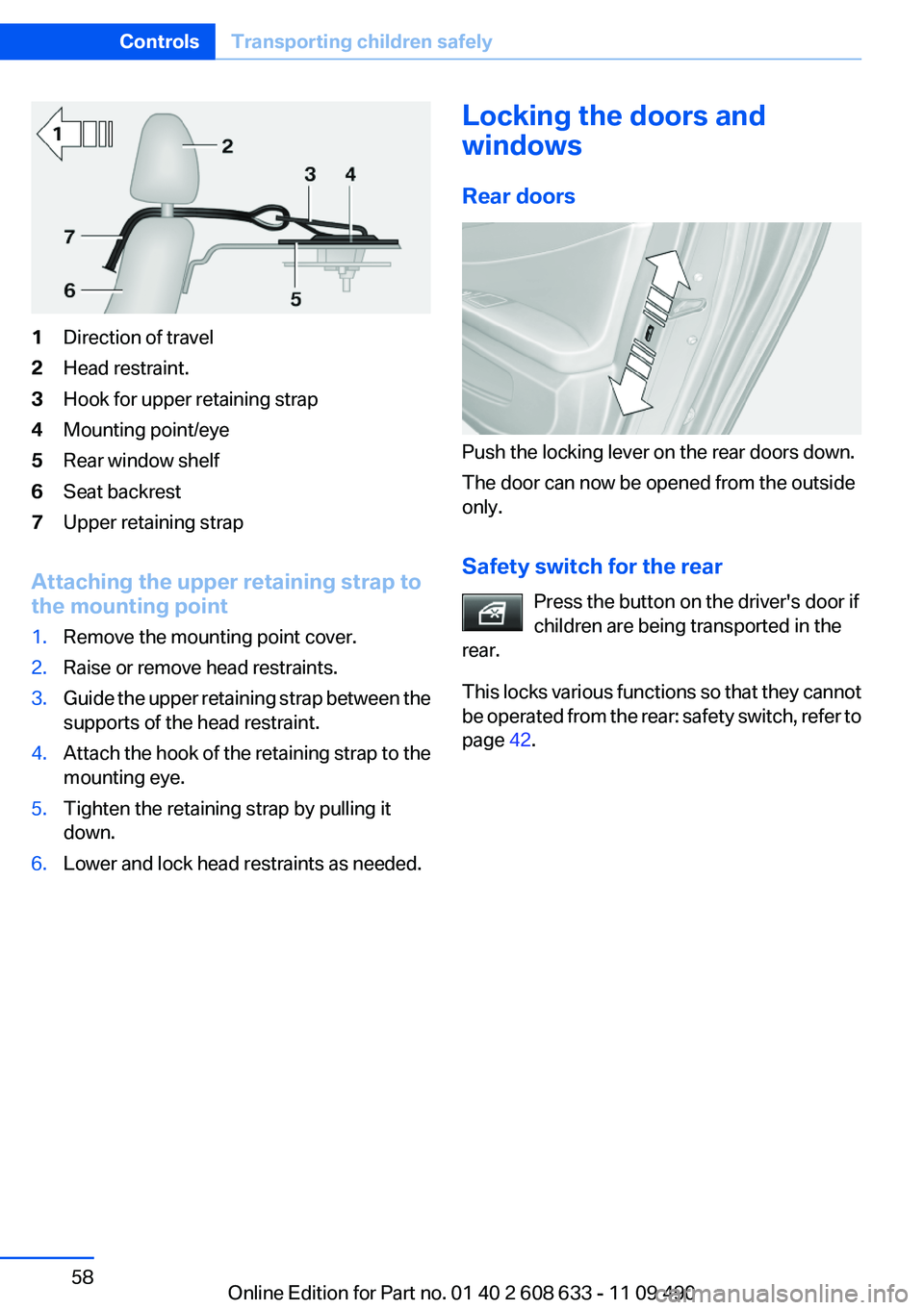
1Direction of travel2Head restraint.3Hook for upper retaining strap4Mounting point/eye5Rear window shelf6Seat backrest7Upper retaining strap
Attaching the upper retaining strap to
the mounting point
1.Remove the mounting point cover.2.Raise or remove head restraints.3.Guide the upper retaining strap between the
supports of the head restraint.4.Attach the hook of the retaining strap to the
mounting eye.5.Tighten the retaining strap by pulling it
down.6.Lower and lock head restraints as needed.Locking the doors and
windows
Rear doors
Push the locking lever on the rear doors down.
The door can now be opened from the outside
only.
Safety switch for the rear Press the button on the driver's door if
children are being transported in the
rear.
This locks various functions so that they cannot
be operated from the rear: safety switch, refer to
page 42.
Seite 58ControlsTransporting children safely58
Online Edition for Part no. 01 40 2 608 633 - 11 09 490
Page 68 of 325
Depress the brake until you start driv‐
ing
To prevent the vehicle from creeping after
you select a driving position, maintain pres‐
sure on the brake pedal until you are ready
to start.◀
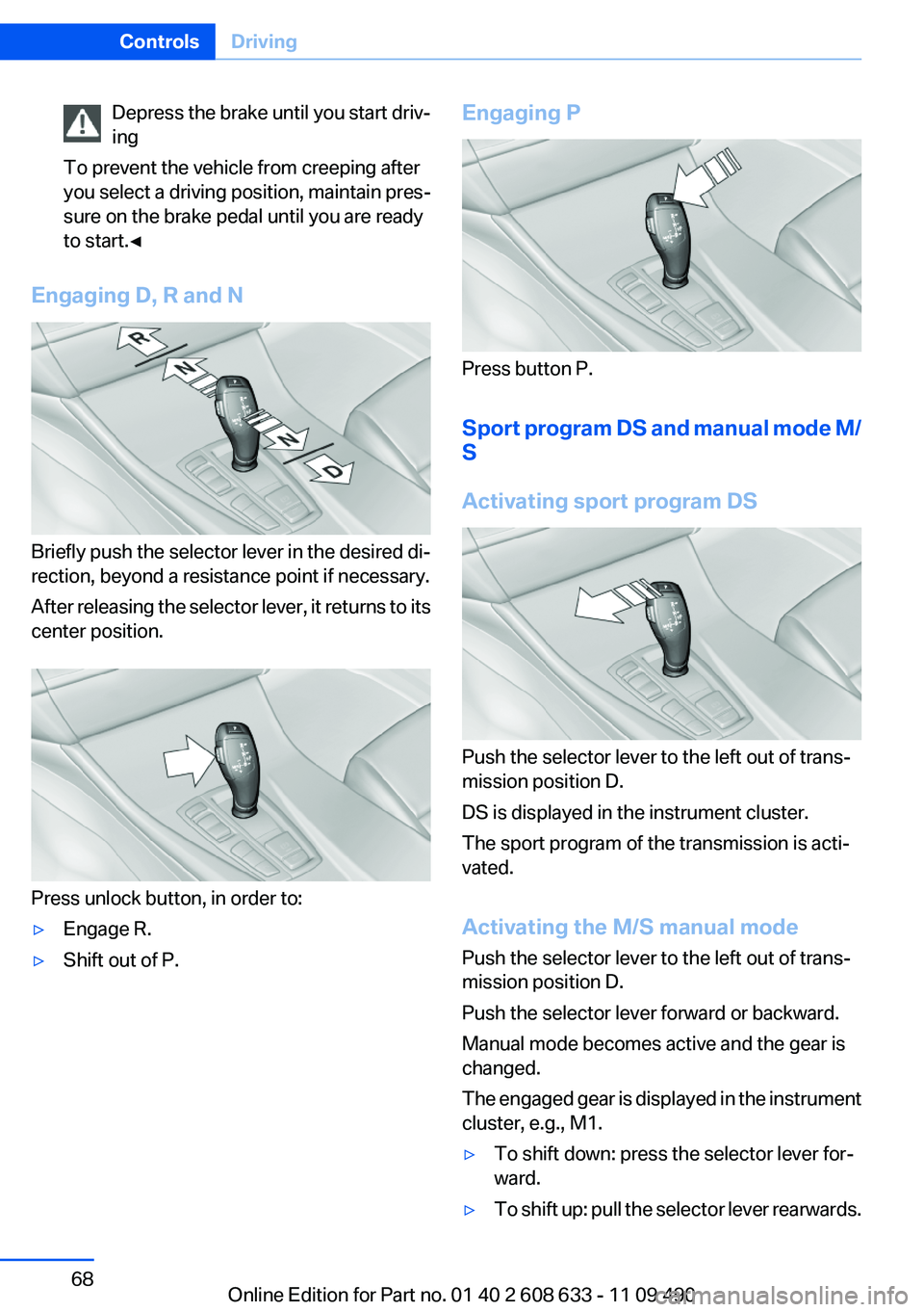
Engaging D, R and N
Briefly push the selector lever in the desired di‐
rection, beyond a resistance point if necessary.
After releasing the selector lever, it returns to its
center position.
Press unlock button, in order to:
▷Engage R.▷Shift out of P.Engaging P
Press button P.
Sport program DS and manual mode M/
S
Activating sport program DS
Push the selector lever to the left out of trans‐
mission position D.
DS is displayed in the instrument cluster.
The sport program of the transmission is acti‐
vated.
Activating the M/S manual mode
Push the selector lever to the left out of trans‐
mission position D.
Push the selector lever forward or backward.
Manual mode becomes active and the gear is
changed.
The engaged gear is displayed in the instrument
cluster, e.g., M1.
▷To shift down: press the selector lever for‐
ward.▷To shift up: pull the selector lever rearwards.Seite 68ControlsDriving68
Online Edition for Part no. 01 40 2 608 633 - 11 09 490
Page 69 of 325
The vehicle only shifts up or down at appropriate
engine and road speeds, e.g., it does not shift
down if the engine speed is too high.
The selected gear is briefly displayed in the in‐
strument cluster, followed by the current gear.
Manual mode M/S: prevent automatic
upshifting
Once maximum engine speed is attained, M/S
manual mode is automatically upshifted as
needed.
For vehicles with Sport automatic transmis‐
sions, automatic shift operations are not per‐
formed if one of the following conditions is met:▷DSC deactivated.▷TRACTION activated.▷SPORT+ activated.
In addition, the kickdown is deactivated.
Ending the sport program/manual
mode
Push the selector lever to the right.
D is displayed in the instrument cluster.
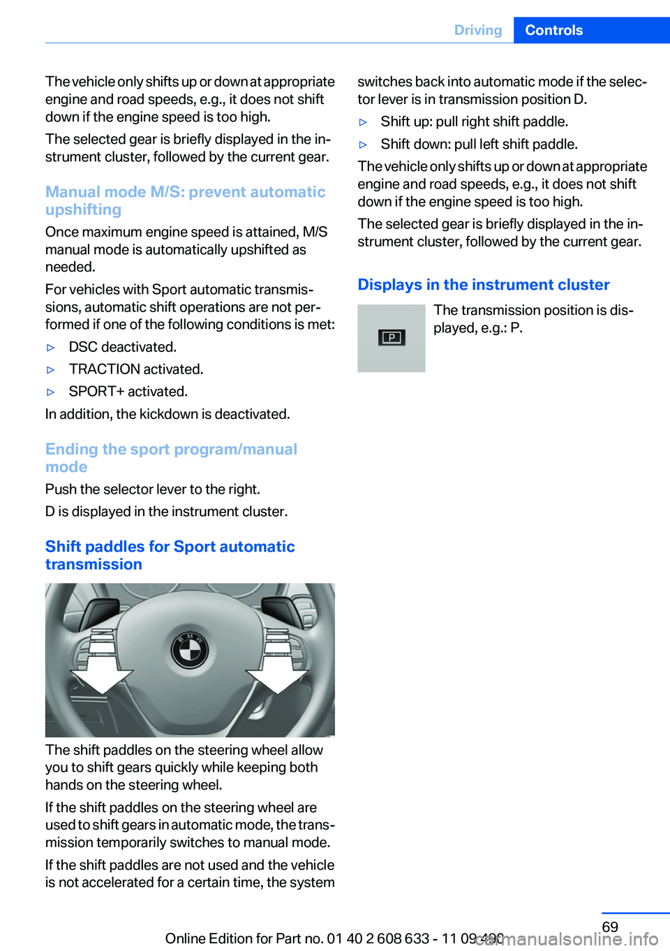
Shift paddles for Sport automatic
transmission
The shift paddles on the steering wheel allow
you to shift gears quickly while keeping both
hands on the steering wheel.
If the shift paddles on the steering wheel are
used to shift gears in automatic mode, the trans‐
mission temporarily switches to manual mode.
If the shift paddles are not used and the vehicle
is not accelerated for a certain time, the system
switches back into automatic mode if the selec‐
tor lever is in transmission position D.▷Shift up: pull right shift paddle.▷Shift down: pull left shift paddle.
The vehicle only shifts up or down at appropriate
engine and road speeds, e.g., it does not shift
down if the engine speed is too high.
The selected gear is briefly displayed in the in‐
strument cluster, followed by the current gear.
Displays in the instrument cluster The transmission position is dis‐
played, e.g.: P.
Seite 69DrivingControls69
Online Edition for Part no. 01 40 2 608 633 - 11 09 490
Page 83 of 325
3."Warning"4.Press the controller.
Applying your current speed as the
limit
1."Settings"2."Speed"3."Select current speed"4.Press the controller.
The current vehicle speed is stored as the
limit.
Trip computer
There are two types of computer.
▷"Onboard info": the values can be reset as
often as necessary.▷" Trip computer": the values provide an over‐
view of the current trip.
Resetting the trip computer
1."Vehicle Info"2."Trip computer"3."Reset": all values are reset.
"Automatically reset": all values are reset
approx. 4 hours after the vehicle comes to a
standstill.
Display on the Control Display
Display the computer or trip computer on the
Control Display.
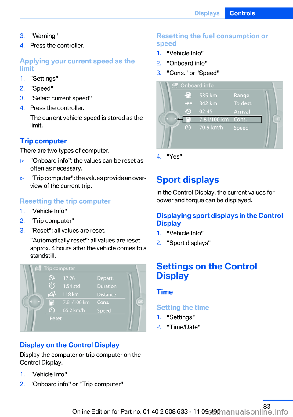
1."Vehicle Info"2."Onboard info" or "Trip computer"Resetting the fuel consumption or
speed1."Vehicle Info"2."Onboard info"3."Cons." or "Speed"4."Yes"
Sport displays
In the Control Display, the current values for
power and torque can be displayed.
Displaying sport displays in the Control
Display
1."Vehicle Info"2."Sport displays"
Settings on the Control
Display
Time
Setting the time
1."Settings"2."Time/Date"Seite 83DisplaysControls83
Online Edition for Part no. 01 40 2 608 633 - 11 09 490
Page 93 of 325
When there is a malfunction, have the air‐
bag system checked immediately
When there is a malfunction, have the airbag
system checked immediately; otherwise, there
is a risk that the system does not function as ex‐
pected in the event of an accident despite cor‐
responding severity of the accident.◀
Automatic deactivation of the front
passenger airbags
The system determines whether the front pas‐
senger seat is occupied by measuring the re‐
sistance of the human body.
The front, knee, and side airbag on the front
passenger side are activated or deactivated ac‐
cordingly.
Leave feet in the footwell
Make sure that the front passenger keeps
his or her feet in the footwell; otherwise, the front
passenger airbags may not function properly.◀
Child restraint fixing system in the front
passenger seat
Before transporting a child on the front passen‐
ger seat, see the safety notes and instructions
under Children on the front passenger seat.◀
Malfunction of the automatic
deactivation system
When transporting older children and adults, the
front passenger airbags may be deactivated in
certain sitting positions. In this case, the indica‐
tor lamp for the front passenger airbags lights
up.
In this case, change the sitting position so that
the front passenger airbags are activated and
the indicator lamp goes out.
If it is not possible to activate the airbags, have
the person sit in the rear.
To make sure that the occupied seat cushion
can be evaluated correctly▷Do not attach covers, cushions, ball mats or
other items to the front passenger seat un‐less they are specifically recommended by
the manufacturer of your vehicle.▷Do not place any electronic devices on the
passenger seat if a child restraint system is
to be installed on it.▷Do not place objects under the seat that
could press against the seat from below.
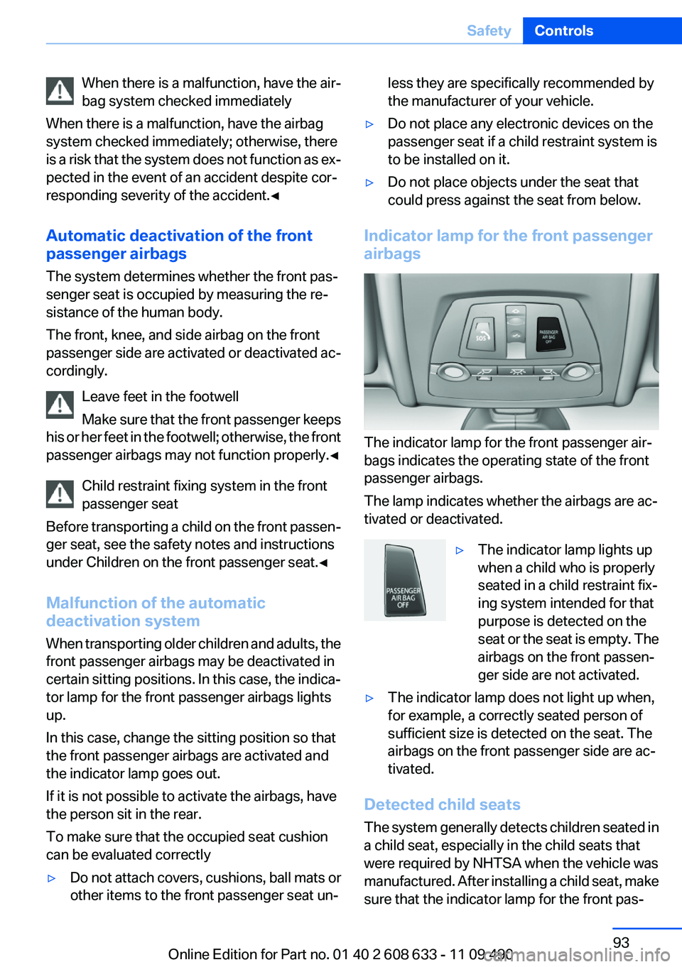
Indicator lamp for the front passenger
airbags
The indicator lamp for the front passenger air‐
bags indicates the operating state of the front
passenger airbags.
The lamp indicates whether the airbags are ac‐
tivated or deactivated.
▷The indicator lamp lights up
when a child who is properly
seated in a child restraint fix‐
ing system intended for that
purpose is detected on the
seat or the seat is empty. The
airbags on the front passen‐
ger side are not activated.▷The indicator lamp does not light up when,
for example, a correctly seated person of
sufficient size is detected on the seat. The
airbags on the front passenger side are ac‐
tivated.
Detected child seats
The system generally detects children seated in
a child seat, especially in the child seats that
were required by NHTSA when the vehicle was
manufactured. After installing a child seat, make
sure that the indicator lamp for the front pas‐
Seite 93SafetyControls93
Online Edition for Part no. 01 40 2 608 633 - 11 09 490
Page 98 of 325

A natural, even pressure loss in all four tires can‐
not be detected. Therefore, check the tire infla‐
tion pressure regularly.
The system could be delayed or malfunction in
the following situations:▷When the system has not been initialized.▷When driving on a snowy or slippery road
surface.▷Sporty driving style: slip in the drive wheels,
high lateral acceleration.▷When driving with snow chains.
Status display
The current status of the Flat Tire Monitor can
be displayed on the Control Display, e.g.,
whether or not the FTM is active.
1."Vehicle Info"2."Vehicle status"3. "Flat Tire Monitor"
The status is displayed.
Initialization
The initialization process adopts the set inflation
tire pressures as reference values for the detec‐
tion of a flat tire. Initialization is started by con‐
firming the inflation pressures.
Do not initialize the system when driving with
snow chains.
1."Vehicle Info"2."Vehicle status"3. "Reset"4.Start the engine - do not drive away.5.Start the initialization with "Reset".6.Drive away.
The initialization is completed while driving,
which can be interrupted at any time.
The initialization automatically continues when
driving resumes.
Indication of a flat tire
The yellow warning lamp lights up. A
Check Control message is displayed.
There is a flat tire or a major loss in tire
inflation pressure.1.Reduce your speed and stop cautiously.
Avoid sudden braking and steering maneu‐
vers.2.Check whether the vehicle is fitted with reg‐
ular tires or run-flat tires.
Run-flat tires, refer to page 271, are labeled
with a circular symbol containing the letters
RSC marked on the tire sidewall.
Do not continue driving without run-flat
tires
Do not continue driving if the vehicle is not
equipped with run-flat tires; continued driving
may result in serious accidents.◀
When a flat tire is indicated, DSC Dynamic Sta‐
bility Control is switched on if necessary.
Actions in the event of a flat tire
Normal tires
1.Identify the damaged tire.
Do this by checking the air pressure in all
four tires.
If the tire inflation pressure in all four tires is
correct, the Flat Tire Monitor may not have
been initialized. In this case, initialize the
system.
If an identification is not possible, please
contact the service center.2.Rectify the flat tire.
Run-flat tires
Maximum speed
You can continue driving with a damaged tire at
speeds up to 50 mph/80 km/h.
Seite 98ControlsSafety98
Online Edition for Part no. 01 40 2 608 633 - 11 09 490
Page 105 of 325

Indicator/warning lamps
When DSC is deactivated, DSC OFF is dis‐
played in the instrument cluster.
The indicator lamp lights up: DSC is de‐
activated.
DTC Dynamic Traction
Control
The concept
The DTC system is a version of the DSC in which
forward momentum is optimized.
The system ensures maximum forward momen‐
tum on special road conditions, e.g., unplowed
snowy roads, but driving stability is limited.
It is therefore necessary to drive with appropri‐
ate caution.
You may find it useful to briefly activate DTC un‐
der the following special circumstances:▷When driving in slush or on uncleared,
snow-covered roads.▷When rocking the vehicle or driving off in
deep snow or on loose surfaces.▷When driving with snow chains.
Deactivating/activating DTC Dynamic
Traction Control
Activating the Dynamic Traction Control DTC
provides maximum traction on loose ground.
Driving stability is limited during acceleration
and when driving in bends.
Activating DTC Press the button.
TRACTION is displayed in the instru‐
ment cluster and the indicator lamp for DSC
OFF lights up.
Deactivating DTC
Press the button again.
TRACTION and the DSC OFF indicator
lamp go out.
Dynamic Damping Control
The concept
This system reduces undesirable vehicle mo‐
tion when using a dynamic driving style or trav‐
eling on uneven road surfaces.
The system enhances driving dynamics and
comfort as required for the road surface and
driving style.
Programs
The system offers two different programs.
The programs can be selected via Dynamic Driv‐
ing Control, refer to page 106.
SPORT
Consistently sporty control of the shock absorb‐
ers for greater driving agility.
SPORT+
Consistently sporty control of the shock absorb‐
ers for greater driving agility when driving with
limited driving stabilization.
COMFORT
Balanced control of the vehicle.
Variable sport steering
The variable sport steering increases the steer‐
ing angle of the front wheels at large steering
wheel angles, e.g., in tight curves or when park‐
ing. Steering becomes more direct.
It also varies the force required to turn the
wheels in accordance with the vehicle speed.Seite 105Driving stability control systemsControls105
Online Edition for Part no. 01 40 2 608 633 - 11 09 490