2011 YAMAHA YZ125LC oil type
[x] Cancel search: oil typePage 49 of 166

3-8
ENGINE
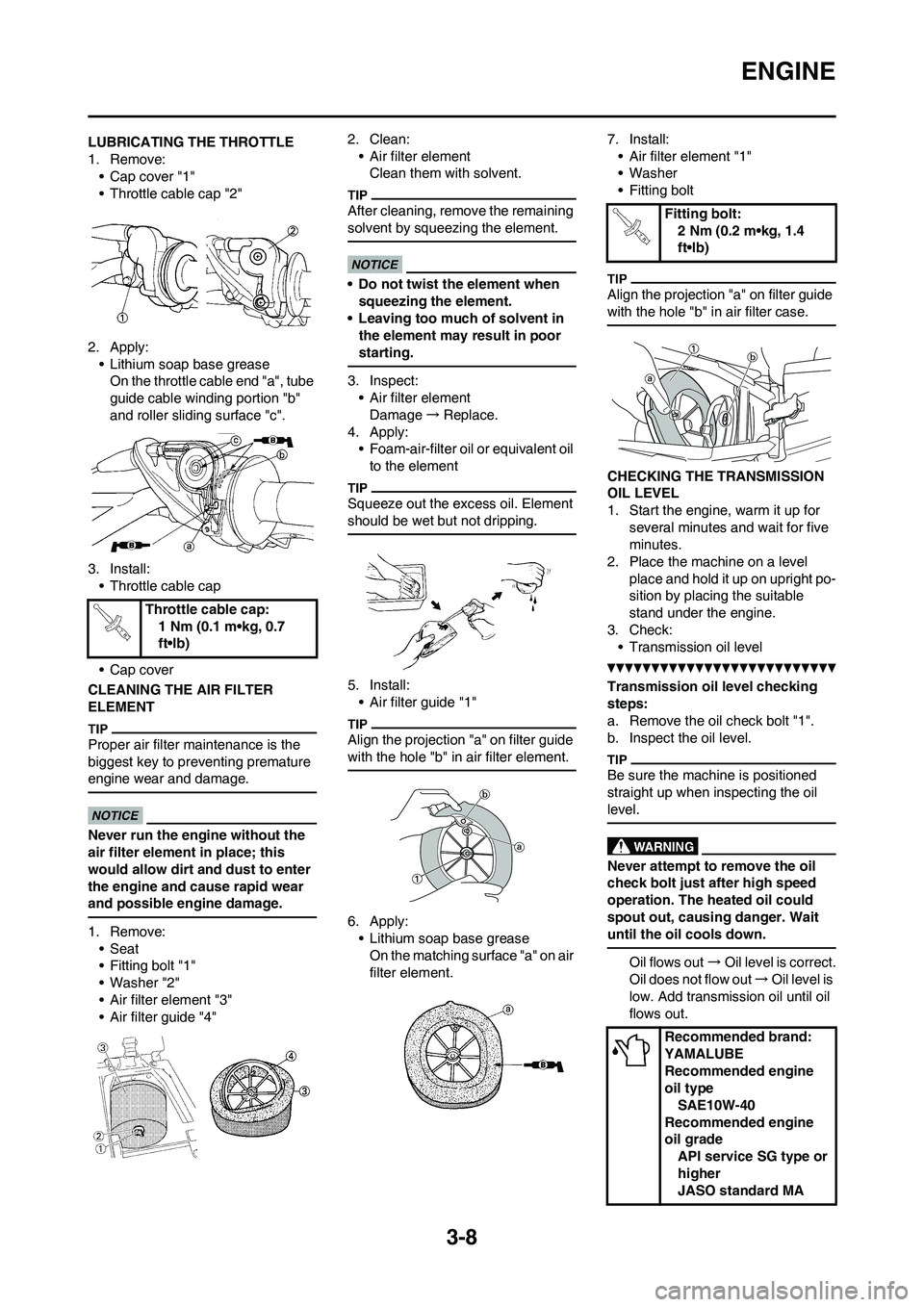
LUBRICATING THE THROTTLE
1. Remove:
• Cap cover "1"
• Throttle cable cap "2"
2. Apply:
• Lithium soap base grease
On the throttle cable end "a", tube
guide cable winding portion "b"
and roller sliding surface "c".
3. Install:
• Throttle cable cap
• Cap cover
CLEANING THE AIR FILTER
ELEMENT
Proper air filter maintenance is the
biggest key to preventing premature
engine wear and damage.
Never run the engine without the
air filter element in place; this
would allow dirt and dust to enter
the engine and cause rapid wear
and possible engine damage.
1. Remove:
• Seat
• Fitting bolt "1"
• Washer "2"
• Air filter element "3"
• Air filter guide "4"2. Clean:
• Air filter element
Clean them with solvent.
After cleaning, remove the remaining
solvent by squeezing the element.
• Do not twist the element when
squeezing the element.
• Leaving too much of solvent in
the element may result in poor
starting.
3. Inspect:
• Air filter element
Damage→Replace.
4. Apply:
• Foam-air-filter oil or equivalent oil
to the element
Squeeze out the excess oil. Element
should be wet but not dripping.
5. Install:
• Air filter guide "1"
Align the projection "a" on filter guide
with the hole "b" in air filter element.
6. Apply:
• Lithium soap base grease
On the matching surface "a" on air
filter element.7. Install:
• Air filter element "1"
• Washer
• Fitting bolt
Align the projection "a" on filter guide
with the hole "b" in air filter case.
CHECKING THE TRANSMISSION
OIL LEVEL
1. Start the engine, warm it up for
several minutes and wait for five
minutes.
2. Place the machine on a level
place and hold it up on upright po-
sition by placing the suitable
stand under the engine.
3. Check:
• Transmission oil level
Transmission oil level checking
steps:
a. Remove the oil check bolt "1".
b. Inspect the oil level.
Be sure the machine is positioned
straight up when inspecting the oil
level.
Never attempt to remove the oil
check bolt just after high speed
operation. The heated oil could
spout out, causing danger. Wait
until the oil cools down.
Oil flows out→Oil level is correct.
Oil does not flow out→Oil level is
low. Add transmission oil until oil
flows out. Throttle cable cap:
1 Nm (0.1 m•kg, 0.7
ft•lb)
Fitting bolt:
2 Nm (0.2 m•kg, 1.4
ft•lb)
Recommended brand:
YAMALUBE
Recommended engine
oil type
SAE10W-40
Recommended engine
oil grade
API service SG type or
higher
JASO standard MA
Page 50 of 166

3-9
CHASSIS
c. Inspect the gasket (oil check bolt),
replace if damaged.
d. Tighten the oil check bolt.
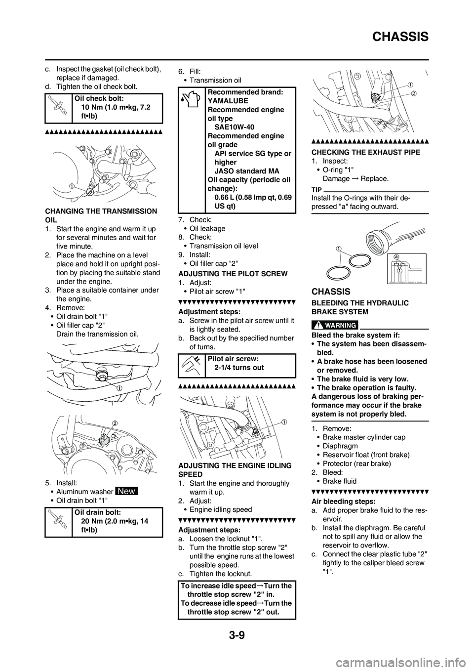
CHANGING THE TRANSMISSION
OIL
1. Start the engine and warm it up
for several minutes and wait for
five minute.
2. Place the machine on a level
place and hold it on upright posi-
tion by placing the suitable stand
under the engine.
3. Place a suitable container under
the engine.
4. Remove:
• Oil drain bolt "1"
• Oil filler cap "2"
Drain the transmission oil.
5. Install:
• Aluminum washer
• Oil drain bolt "1"6. Fill:
• Transmission oil
7. Check:
• Oil leakage
8. Check:
• Transmission oil level
9. Install:
• Oil filler cap "2"
ADJUSTING THE PILOT SCREW
1. Adjust:
• Pilot air screw "1"
Adjustment steps:
a. Screw in the pilot air screw until it
is lightly seated.
b. Back out by the specified number
of turns.
ADJUSTING THE ENGINE IDLING
SPEED
1. Start the engine and thoroughly
warm it up.
2. Adjust:
• Engine idling speed
Adjustment steps:
a. Loosen the locknut "1".
b. Turn the throttle stop screw "2"
until the engine runs at the lowest
possible speed.
c. Tighten the locknut.
CHECKING THE EXHAUST PIPE
1. Inspect:
• O-ring "1"
Damage→Replace.
Install the O-rings with their de-
pressed "a" facing outward.
CHASSIS
BLEEDING THE HYDRAULIC
BRAKE SYSTEM
Bleed the brake system if:
• The system has been disassem-
bled.
• A brake hose has been loosened
or removed.
• The brake fluid is very low.
• The brake operation is faulty.
A dangerous loss of braking per-
formance may occur if the brake
system is not properly bled.
1. Remove:
• Brake master cylinder cap
• Diaphragm
• Reservoir float (front brake)
• Protector (rear brake)
2. Bleed:
• Brake fluid
Air bleeding steps:
a. Add proper brake fluid to the res-
ervoir.
b. Install the diaphragm. Be careful
not to spill any fluid or allow the
reservoir to overflow.
c. Connect the clear plastic tube "2"
tightly to the caliper bleed screw
"1". Oil check bolt:
10 Nm (1.0 m•kg, 7.2
ft•lb)
Oil drain bolt:
20 Nm (2.0 m•kg, 14
ft•lb)
Recommended brand:
YAMALUBE
Recommended engine
oil type
SAE10W-40
Recommended engine
oil grade
API service SG type or
higher
JASO standard MA
Oil capacity (periodic oil
change):
0.66 L (0.58 Imp qt, 0.69
US qt)
Pilot air screw:
2-1/4 turns out
To increase idle speed→Turn the
throttle stop screw "2" in.
To decrease idle speed→Turn the
throttle stop screw "2" out.
Page 120 of 166

5-14
FRONT BRAKE AND REAR BRAKE
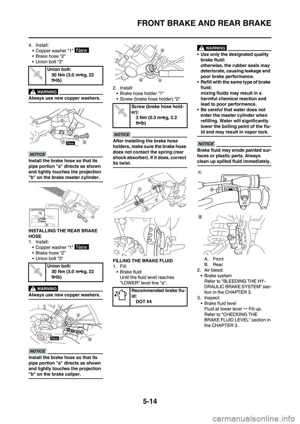
4. Install:
• Copper washer "1"
• Brake hose "2"
• Union bolt "3"
Always use new copper washers.
Install the brake hose so that its
pipe portion "a" directs as shown
and lightly touches the projection
"b" on the brake master cylinder.
INSTALLING THE REAR BRAKE
HOSE
1. Install:
• Copper washer "1"
• Brake hose "2"
• Union bolt "3"
Always use new copper washers.
Install the brake hose so that its
pipe portion "a" directs as shown
and lightly touches the projection
"b" on the brake caliper.
2. Install:
• Brake hose holder "1"
• Screw (brake hose holder) "2"
After installing the brake hose
holders, make sure the brake hose
does not contact the spring (rear
shock absorber). If it does, correct
its twist.
FILLING THE BRAKE FLUID
1. Fill:
•Brake fluid
Until the fluid level reaches
"LOWER" level line "a".
• Use only the designated quality
brake fluid:
otherwise, the rubber seals may
deteriorate, causing leakage and
poor brake performance.
• Refill with the same type of brake
fluid;
mixing fluids may result in a
harmful chemical reaction and
lead to poor performance.
• Be careful that water does not
enter the master cylinder when
refilling. Water will significantly
lower the boiling point of the flu-
id and may result in vapor lock.
Brake fluid may erode painted sur-
faces or plastic parts. Always
clean up spilled fluid immediately.
A. Front
B. Rear
2. Air bleed:
• Brake system
Refer to "BLEEDING THE HY-
DRAULIC BRAKE SYSTEM" sec-
tion in the CHAPTER 3.
3. Inspect:
• Brake fluid level
Fluid at lower level→Fill up.
Refer to "CHECKING THE
BRAKE FLUID LEVEL" section in
the CHAPTER 3. Union bolt:
30 Nm (3.0 m•kg, 22
ft•lb)
Union bolt:
30 Nm (3.0 m•kg, 22
ft•lb)
Screw (brake hose hold-
er):
3 Nm (0.3 m•kg, 2.2
ft•lb)
Recommended brake flu-
id:
DOT #4
Page 146 of 166

5-40
REAR SHOCK ABSORBER
HANDLING NOTE
• Support the machine securely so
there is no danger of it falling
over.
• This rear shock absorber is pro-
vided with a separate type tank
filled with high-pressure nitro-
gen gas. To prevent the danger
of explosion, read and under-
stand the following information
before handling the shock ab-
sorber. The manufacturer can
not be held responsible for prop-
erty damage or personal injury
that may result from improper
handling.
• Never tamper or attempt to dis-
assemble the cylinder or the
tank.
• Never throw the rear shock ab-
sorber into an open flame or
other high heat. The rear shock
absorber may explode as a re-
sult of nitrogen gas expansion
and/ or damage to the hose.
• Be careful not to damage any
part of the gas tank. A damaged
gas tank will impair the damp-
ing performance or cause a
malfunction.
• Take care not to scratch the
contact surface of the piston
rod with the cylinder; or oil
could leak out.
• Never attempt to remove the
plug at the bottom of the nitro-
gen gas tank. It is very danger-
ous to remove the plug.
• When scrapping the rear shock
absorber, follow the instruc-
tions on disposal.
NOTES ON DISPOSAL (YAMAHA
DEALERS ONLY)
Before disposing the rear shock ab-
sorber, be sure to extract the nitrogen
gas from valve "1". Wear eye protec-
tion to prevent eye damage from es-
caping gas and/or metal chips.
To dispose of a damaged or worn-
out rear shock absorber, take the
unit to your Yamaha dealer for this
disposal procedure.
REMOVING THE BEARING
1. Remove:
• Stopper ring (upper bearing) "1"
Press in the bearing while pressing its
outer race and remove the stopper
ring.
2. Remove:
• Upper bearing "1"
Remove the bearing by pressing its
outer race.
3. Remove:
• Lower bearing "1"
Remove the bearing by pressing its
outer race.
CHECKING THE REAR SHOCK
ABSORBER
1. Inspect:
• Damper rod "1"
Bends/damage→Replace rear
shock absorber assembly.
• Shock absorber "2"
Oil leaks→Replace rear shock
absorber assembly.
Gas leaks→Replace rear shock
absorber assembly.
• Spring "3"
Damage→Replace spring.
Fatigue→Replace spring.
Move spring up and down.
• Spring guide "4"
Wear/damage→Replace spring
guide.
• Spring seat "5"
Cracks/damage →Replace.
• Bearing "6"
Free play exists/unsmooth revolu-
tion/rust →Replace.
INSTALLING THE BEARING
1. Install:
• Upper bearing "1"
Install the bearing parallel until the
stopper ring groove appears by
pressing its outer race.
Do not apply the grease on the
bearing outer race because it will
wear the rear shock absorber sur-
face on which the bearing is press
fitted.
Page 154 of 166

7-1
ENGINE
TUNING
ENGINE
CARBURETOR SETTING
• The role of fuel is to cool the engine, and in the case of a 2-stroke en-
gine, to lubricate the engine in addi-
tion to power generation.
Accordingly, if a mixture of air and
fuel is too lean, abnormal combus-
tion will occur, and engine seizure
may result. If the mixture is too rich,
spark plugs will get wet with oil, thus
making it impossible to bring the en-
gine into full play or if the worst
comes to the worst, the engine may
stall.
• The richness of the air-fuel mixture
required for the engine will vary with
atmospheric conditions of the day
and therefore, the settings of the
carburetor must be properly suited
to the atmospheric conditions (air
pressure, humidity and tempera-
ture).
• Finally, the rider himself must make a test-run and check his machine
for conditions (pick-up of engine
speed, road surface conditions)
and for the discoloration of the
spark plug(s). After taking these
into consideration, he must select
the best possible carburetor set-
tings.
It is advisable to make a note of set-
tings, atmospheric conditions, road
surface condition, lap-time, etc. so
that the memorandum can be used
as a reference useful for future.
ATMOSPHERIC CONDITIONS AND
CARBURETOR SETTINGS
The reason for the above tendency is
that the richness or leanness of a fuel
mixture depends on the density of the
air (i.e. the concentration of oxygen in
it).
• Higher temperature expands the air with its resultant reduced density. • Higher humidity reduces the
amount of oxygen in the air by so
much of the water vapor in the
same air.
• Lower atmospheric pressure (at a high altitude) reduces the density of
the air.
TEST RUN
After warming up the engine
equipped with the standard type car-
buretor(s) and spark plug(s), run two
or three laps of the circuit and check
the smooth operation of the engine
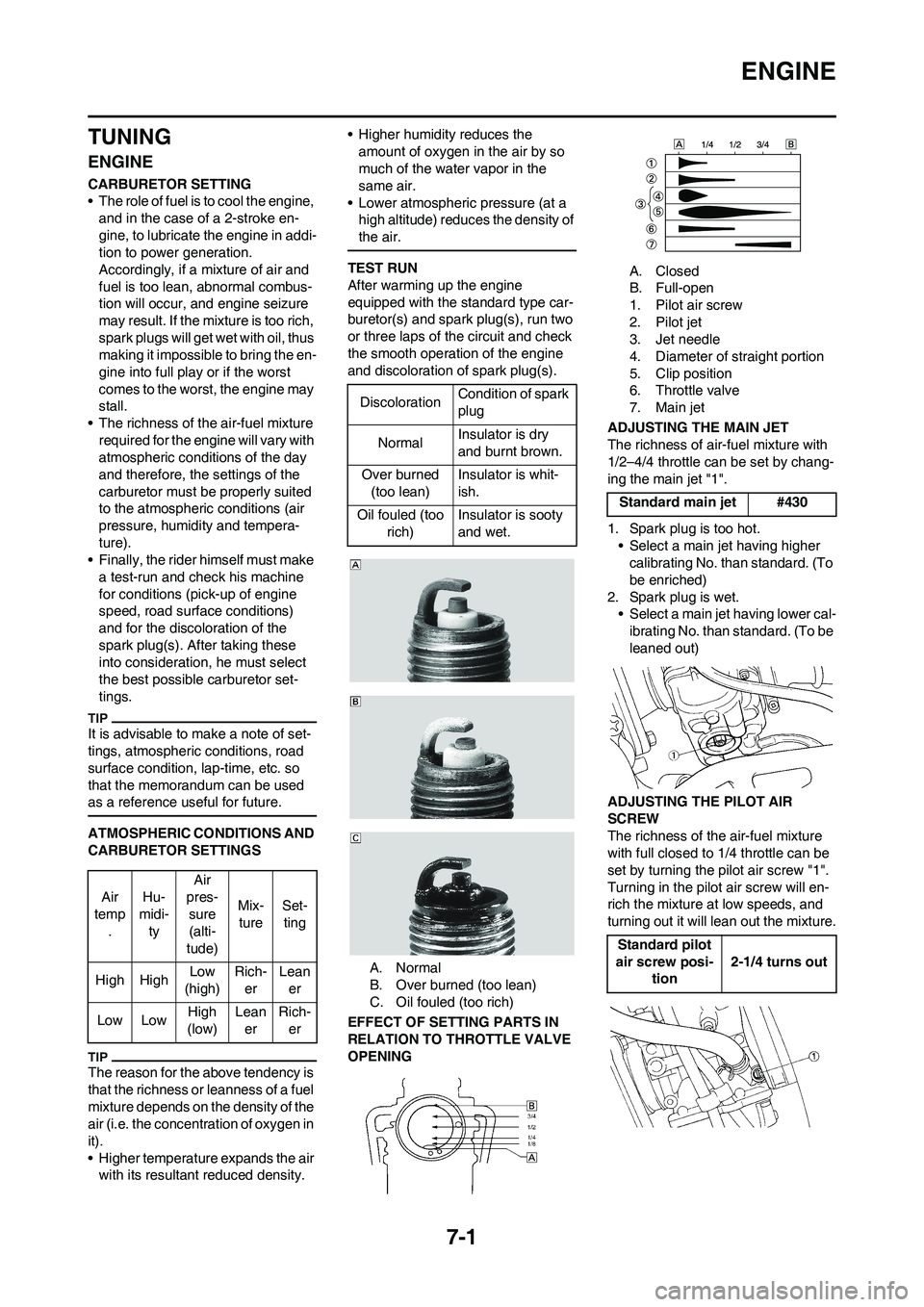
and discoloration of spark plug(s).
A. Normal
B. Over burned (too lean)
C. Oil fouled (too rich)
EFFECT OF SETTING PARTS IN
RELATION TO THROTTLE VALVE
OPENING A. Closed
B. Full-open
1. Pilot air screw
2. Pilot jet
3. Jet needle
4. Diameter of straight portion
5. Clip position
6. Throttle valve
7. Main jet
ADJUSTING THE MAIN JET
The richness of air-fuel mixture with
1/2–4/4 throttle can be set by chang-
ing the main jet "1".
1. Spark plug is too hot. • Select a main jet having higher calibrating No. than standard. (To
be enriched)
2. Spark plug is wet. • Select a main jet having lower cal-
ibrating No. than standard. (To be
leaned out)
ADJUSTING THE PILOT AIR
SCREW
The richness of the air-fuel mixture
with full closed to 1/4 throttle can be
set by turning the pilot air screw "1".
Turning in the pilot air screw will en-
rich the mixture at low speeds, and
turning out it will lean out the mixture.
Air
temp . Hu-
midi- ty Air
pres- sure
(alti-
tude) Mix-
ture Set-
ting
High High Low
(high) Rich-
er Lean
er
Low Low High
(low) Lean
er Rich-
er
Discoloration Condition of spark
plug
Normal Insulator is dry
and burnt brown.
Over burned (too lean) Insulator is whit-
ish.
Oil fouled (too rich) Insulator is sooty
and wet.
Standard main jet #430
Standard pilot
air screw posi- tion 2-1/4 turns out
Page 159 of 166

7-6
CHASSIS
CHANGE OF THE HEAT RANGE
OF SPARK PLUGS
Judging from the discoloration of
spark plugs, if they are found improp-
er, it can be corrected by the following
two methods; changing carburetor
settings and changing the heat range
of spark plug.
• In principle, it is advisable to first
use spark plugs of standard heat
range, and judging from the discol-
oration of spark plugs, adjust carbu-
retor settings.
• If the calibration No. of the main jet
must be changed by ±30, it is advis-
able to change the heat range of
spark plugs and newly select the
proper main jet.
• When checking the discoloration of
spark plugs, be sure to stop the en-
gine immediately after a run and
check.
• Avoid racing.
• When changing the heat range of
spark plugs, never attempt to
change it more than ±1 rank.
• When using a spark plug other than
standard, check its heat range
against the standard and check that
it is a resistance type.
• Note that even if the discoloration
seems proper, it may slightly vary
with the spark plug maker and oil in
use.
CHASSIS
SELECTION OF THE SECONDARY
REDUCTION RATIO (SPROCKET)
• It is generally said that the second-
ary gear ratio should be reduced for
a longer straight portion of a speed
course and should be increased for
a course with many corners. Actual-
ly, however, as the speed depends
on the ground condition of the day
of the race, be sure to run through
the circuit to set the machine suit-
able for the entire course.
• In actuality, it is very difficult to
achieve settings suitable for the en-
tire course and some settings may
be sacrificed. Thus, the settings
should be matched to the portion of
the course that has the greatest ef-
fect on the race result. In such a
case, run through the entire course
while making notes of lap times to
find the best balance; then, deter-
mine the secondary reduction ratio.
• If a course has a long straight por-
tion where a machine can run at
maximum speed, the machine is
generally set such that it can devel-
op its maximum revolutions toward
the end of the straight line, with care
taken to avoid the engine over-rev-
ving.
Riding technique varies from rider to
rider and the performance of a ma-
chine also vary from machine to ma-
chine. Therefore, do not imitate other
rider's settings from the beginning but
choose your own setting according to
the level of your riding technique.
DRIVE AND REAR WHEEL
SPROCKETS SETTING PARTSTIRE PRESSURE
Tire pressure should be adjust to suit
the road surface condition of the cir-
cuit.
• Under a rainy, muddy, sandy, or
slippery condition, the tire pressure
should be lower for a larger area of
contact with the road surface.
• Under a stony or hard road condi-
tion, the tire pressure should be
higher to prevent a flat tire.
FRONT FORK SETTING
The front fork setting should be made
depending on the rider's feeling of an
actual run and the circuit conditions.
The front fork setting includes the fol-
lowing three factors:
1. Setting of air spring characteris-
tics
• Change the fork oil amount.
2. Setting of spring preload
• Change the spring.
3. Setting of damping force
• Change the compression damp-
ing.
• Change the rebound damping.
The spring acts on the load and
the damping force acts on the
cushion travel speed.
CHANGE IN AMOUNT AND
CHARACTERISTICS OF FORK OIL
Damping characteristic near the final
stroke can be changed by changing
the fork oil amount. Standard spark
plugBR9EVX/NGK
(resistance
type)
Secondary reduction ratio =
Number of rear wheel sprocket
teeth/Number of drive sprocket
teeth
Standard second-
ary reduction ratio48/13 (3.692)
Part name Size Part number
Drive
sprocket
"1"
(STD) 13T 9383B-13218
Rear wheel
sprocket
"2"
47T 1C3-25447-00
(STD) 48T 1C3-25448-00
49T 1C3-25449-00
50T 1C3-25450-00
51T 1C3-25451-00
52T 1C3-25452-00
Standard tire pressure:
100 kPa (1.0 kgf/cm2,
15 psi)
Extent of adjustment:
60–80 kPa (0.6–0.8 kgf/
cm
2, 9.0–12 psi)
Extent of adjustment:
100–120 kPa (1.0–1.2
kgf/cm
2, 15–18 psi)