Page 57 of 74
PERIODIC MAINTENANCE AND ADJUSTMENT
7-20
7
EAU23120
Adjusting the Autolube pump The Autolube pump is a vital and so-
phisticated component of the engine,
which must be adjusted by a Yamaha
dealer at the intervals specified in the
periodic maintenance and lubrication
chart.
EAU43622
Checking and lubricating the
brake lever The operation of the brake lever should
be checked before each ride, and the
lever pivot should be lubricated if nec-
essary.
EAU23182
Checking and lubricating the
brake pedal The operation of the brake pedal
should be checked before each ride,
and the pedal pivot should be lubricat-
ed if necessary.
Recommended lubricant:
Lithium-soap-based grease
Recommended lubricant:
Lithium-soap-based grease
U3RV8LE0.book Page 20 Tuesday, April 13, 2010 8:48 AM
Page 58 of 74

PERIODIC MAINTENANCE AND ADJUSTMENT
7-21
7
EAU23202
Checking and lubricating the
sidestand The operation of the sidestand should
be checked before each ride, and the
sidestand pivot and metal-to-metal
contact surfaces should be lubricated if
necessary.
WARNING
EWA10731
If the sidestand does not move up
and down smoothly, have a Yamaha
dealer check or repair it. Otherwise,
the sidestand could contact the
ground and distract the operator, re-
sulting in a possible loss of control.
EAU23272
Checking the front fork The condition and operation of the front
fork must be checked as follows at the
intervals specified in the periodic main-
tenance and lubrication chart.
To check the condition
Check the inner tubes for scratches,
damage and excessive oil leakage.
To check the operation
1. Place the vehicle on a level sur-
face and hold it in an upright posi-
tion. WARNING! To avoid injury,
securely support the vehicle so
there is no danger of it falling
over.
[EWA10751]
2. While applying the front brake,
push down hard on the handlebars
several times to check if the front
fork compresses and rebounds
smoothly.
NOTICE
ECA10590
If any damage is found or the front
fork does not operate smoothly,
have a Yamaha dealer check or re-
pair it.
Recommended lubricant:
Lithium-soap-based grease
U3RV8LE0.book Page 21 Tuesday, April 13, 2010 8:48 AM
Page 59 of 74

PERIODIC MAINTENANCE AND ADJUSTMENT
7-22
7
EAU23283
Checking the steering Worn or loose steering bearings may
cause danger. Therefore, the operation
of the steering must be checked as fol-
lows at the intervals specified in the pe-
riodic maintenance and lubrication
chart.
1. Place a stand under the engine to
raise the front wheel off the
ground. (See page 7-22 for more
information.) WARNING! To
avoid injury, securely support
the vehicle so there is no danger
of it falling over.
[EWA10751]
2. Hold the lower ends of the front
fork legs and try to move them for-
ward and backward. If any free
play can be felt, have a Yamaha
dealer check or repair the steering.
EAU23291
Checking the wheel bearings The front and rear wheel bearings must
be checked at the intervals specified in
the periodic maintenance and lubrica-
tion chart. If there is play in the wheel
hub or if the wheel does not turn
smoothly, have a Yamaha dealer check
the wheel bearings.
EAU24350
Supporting the motorcycle Since this model is not equipped with a
centerstand, follow these precautions
when removing the front and rear
wheel or performing other maintenance
requiring the motorcycle to stand up-
right. Check that the motorcycle is in a
stable and level position before starting
any maintenance. A strong wooden
box can be placed under the engine for
added stability.
To service the front wheel
1. Stabilize the rear of the motorcycle
by using a motorcycle stand or, if
an additional motorcycle stand is
not available, by placing a jack un-
der the frame in front of the rear
wheel.
2. Raise the front wheel off the
ground by using a motorcycle
stand.
To service the rear wheel
Raise the rear wheel off the ground by
using a motorcycle stand or, if a motor-
cycle stand is not available, by placing
U3RV8LE0.book Page 22 Tuesday, April 13, 2010 8:48 AM
Page 60 of 74

PERIODIC MAINTENANCE AND ADJUSTMENT
7-23
7a jack either under each side of the
frame in front of the rear wheel or under
each side of the swingarm.
EAU24360
Front wheel
EAU49911
To remove the front wheel
WARNING
EWA10821
To avoid injury, securely support the
vehicle so there is no danger of it
falling over.1. Loosen the brake cable locknut at
the front wheel hub, and then turn
the brake lever free play adjusting
bolt fully in direction (a).
2. Slide the rubber cover back at the
brake lever.3. Loosen the locknut at the brake le-
ver, and then turn the adjusting
bolt fully in direction (a).
4. Disconnect the brake cable from
the front brake lever.
5. Slide the rubber cover down at the
front wheel hub, and then turn the
front brake lever free play adjust-
ing bolt fully in direction (b) to dis-
connect the brake cable from the
front wheel hub.
6. Remove the axle nut and washer.1. Brake lever free play adjusting bolt
2. Locknut
3. Rubber cover3
1
2 (a)
(b)
1. Rubber cover
2. Brake lever free play adjusting bolt
3. Locknut
3 2
1
(a)
U3RV8LE0.book Page 23 Tuesday, April 13, 2010 8:48 AM
Page 61 of 74

PERIODIC MAINTENANCE AND ADJUSTMENT
7-24
7 7. Lift the front wheel off the ground
according to the procedure on
page 7-22.
8. Pull the wheel axle out, and then
remove the wheel.
EAU41553
To install the front wheel
1. Install the brake shoe plate into the
wheel hub as shown.2. Lift the wheel up between the fork
legs.
TIPMake sure that the slot in the brake
shoe plate fits over the retainer on the
fork leg.
3. Insert the wheel axle from the right
side, and then install the washer
and axle nut.
4. Lower the front wheel so that it is
on the ground, and then put the
sidestand down.
5. Connect the brake cable to the
brake camshaft lever.
6. Turn the front brake lever free play
adjusting bolt at the wheel hub in
direction (a), and then slide the
rubber cover to its original position.
7. Connect the brake cable at the
front brake lever.
8. Tighten the axle nut to the speci-
fied torque.
1. Washer
2. Axle nut
2
1
1. Brake shoe plate
1. Retainer
1
1
1. Brake lever free play adjusting bolt
2. Rubber cover
3. Brake camshaft lever23
1
(a)
U3RV8LE0.book Page 24 Tuesday, April 13, 2010 8:48 AM
Page 62 of 74

10. Push down hard on the handlebar
several times to check for proper
fork operation.
EAU25080
Rear whee")
PERIODIC MAINTENANCE AND ADJUSTMENT
7-25
79. Adjust the brake lever free play.
(See page 7-14.)
10. Push down hard on the handlebar
several times to check for proper
fork operation.
EAU25080
Rear wheel
EAU41563
To remove the rear wheel
WARNING
EWA10821
To avoid injury, securely support the
vehicle so there is no danger of it
falling over.1. Loosen the axle nut.
2. Remove the brake pedal free play
adjusting nut, and then disconnect
the brake rod from the brake cam-
shaft lever.3. Disconnect the brake torque rod
from the brake shoe plate by re-
moving the cotter pin, the nut, and
the bolt.
4. Loosen the locknut and drive chain
adjusting nut on each end of the
swingarm.
Tightening torque:
Axle nut:
35 Nm (3.5 m·kgf, 25 ft·lbf)
1. Drive chain slack adjusting nut
2. Locknut
3. Drive chain puller
4. Washer
5. Axle nut
5
41
2
3
1. Brake rod
2. Brake pedal free play adjusting nut
3. Brake camshaft lever
4. Spacer
5. Drive chain puller
6. Wheel axle
7. Drive chain slack adjusting nut
8. Locknut
9. Brake torque rod
10.Brake torque rod bolt
11.Cotter pin
12.Brake torque rod nut
287
46
9
1110
12
1
3
5
U3RV8LE0.book Page 25 Tuesday, April 13, 2010 8:48 AM
Page 63 of 74

PERIODIC MAINTENANCE AND ADJUSTMENT
7-26
7 5. Lift the rear wheel off the ground
according to the procedure on
page 7-22.
6. Remove the axle nut and washer,
and then pull the wheel axle out.
7. Remove the spacer and chain pull-
ers.
8. Push the wheel forward, and then
remove the drive chain from the
rear sprocket.
TIPThe drive chain does not need to be
disassembled in order to remove and
install the wheel.9. Remove the wheel by pulling it
back.
EAU41573
To install the rear wheel
1. Insert the brake shoe plate into the
wheel hub, and then insert the
wheel into the swingarm.
2. Install the drive chain onto the rear
sprocket.
3. Install the wheel by inserting the
chain pullers, spacer and then in-
sert the wheel axle from the right-
hand side.
4. Connect the brake torque rod onto
the brake shoe plate by installing
the bolt and nut, and then tighten
the nut to the specified torque.
5. Insert a new cotter pin into the
brake torque rod bolt. WARNING!
Always use a new cotter pin.
[EWA10831]
6. Install the brake rod into the brake
camshaft lever, and then install the
brake pedal free play adjusting nut
onto the brake rod.
7. Install the washer and axle nut.8. Lower the rear wheel so that it is
on the ground, and then put the
sidestand down.
9. Adjust the drive chain slack. (See
page 7-17.)
10. Tighten the axle nut to the speci-
fied torque.
11. Adjust the brake pedal free play.
(See page 7-15.)Tightening torque:
Brake torque rod nut:
16 Nm (1.6 m·kgf, 12 ft·lbf)
Tightening torque:
Axle nut:
60 Nm (6.0 m·kgf, 43 ft·lbf)
U3RV8LE0.book Page 26 Tuesday, April 13, 2010 8:48 AM
Page 64 of 74

PERIODIC MAINTENANCE AND ADJUSTMENT
7-27
7
EAU25851
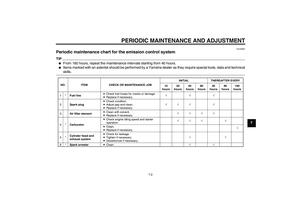
Troubleshooting Although Yamaha motorcycles receive
a thorough inspection before shipment
from the factory, trouble may occur dur-
ing operation. Any problem in the fuel,
compression, or ignition systems, for
example, can cause poor starting and
loss of power.
The following troubleshooting chart
represents a quick and easy procedure
for checking these vital systems your-
self. However, should your motorcycle
require any repair, take it to a Yamaha
dealer, whose skilled technicians have
the necessary tools, experience, and
know-how to service the motorcycle
properly.
Use only genuine Yamaha replace-
ment parts. Imitation parts may look like
Yamaha parts, but they are often inferi-
or, have a shorter service life and can
lead to expensive repair bills.
WARNING
EWA15141
When checking the fuel system, do
not smoke, and make sure there are
no open flames or sparks in the ar-
ea, including pilot lights from waterheaters or furnaces. Gasoline or
gasoline vapors can ignite or ex-
plode, causing severe injury or
property damage.U3RV8LE0.book Page 27 Tuesday, April 13, 2010 8:48 AM