Page 315 of 360

08 Maintenance and specifications
Wiper blades and washer fluid
08
��
315 Wiper blades
The windshield wiper blades are different
lengths. The blade on the driver’s side is longer
than the one on the passenger side.
Service position
Wiper blades in service position
The wiper blades must be in the vertical (serv-
ice) position for replacement, washing or to lift
them away from the windshield when e.g.,
removing ice or snow. To put them in this posi-
tion:
1. While sitting in the driver's seat, close the
driver's door.
2.
Insert the remote key in the ignition slot
1
3.
Put the ignition in mode II (see page 81).4.
With the remote key in the ignition slot
1, put
the ignition in mode 0.
5. Move the right steering wheel lever up and
hold it for at least 1 second. The wipers will
then move to the vertical (service) position
on the windshield.
The wipers can be returned to the normal posi-
tion by briefly switching on the ignition (or by
starting the engine).
Replacing the windshield wiper blades
With the wipers in the service position, fold
out the wiper arm from the windshield.
Press the button on the wiper blade attach-
ment and pull the wiper blade straight out,
parallel with the wiper arm.
Slide in the new wiper blade until it clicks
into place.
Check that the blade is securely in place.
1Not necessary on vehicles with the optional keyless drive.
Page 318 of 360

08 Maintenance and specifications
Battery
08
318
Maintenance
•Use a screw driver to open the caps or
cover and a flashlight to inspect the level.
•If necessary, add distilled water. The level
should never be above the indicator.
•The fluid level should be checked if the
battery has been recharged.
•After inspection, be sure the cap over each
battery cell or the cover is securely in
place.
•Check that the battery cables are correctly
connected and properly tightened.
•Never disconnect the battery when the
engine is running, or when the key is in the
ignition. This could damage the vehicle's
electrical system.
•The battery should be disconnected from
the vehicle when a battery charger is used
directly on the battery.
•To help keep the battery in good condition,
the vehicle should be driven for at least 15
minutes a week or connected to a charger
with an automatic charging function.
•If the battery is fully discharged a number
of times, this may shorten its service life.
Keeping the battery fully charged helps
prolong its service life.
•The service life of a battery is affected by
factors such as driving conditions and cli-mate. Extreme cold may also further
decrease the battery’s starting capacity.
•Because the battery’s starting capacity
decreases with time, it may be necessary
to recharge it if the vehicle is not driven for
an extended period of time or if the vehicle
is usually only driven short distances.
CAUTION
•Always use distilled or deionized water
(battery water).
•Never fill above the level mark in the cell.
Changing
Page 319 of 360

08 Maintenance and specifications
Battery
08
319
WARNING
Connect and disconnect the positive and
negative cables in the correct sequence.
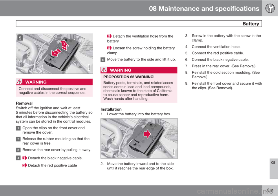
RemovalSwitch off the ignition and wait at least
5 minutes before disconnecting the battery so
that all information in the vehicle's electrical
system can be stored in the control modules.
Open the clips on the front cover and
remove the cover.
Release the rubber moulding so that the
rear cover is free.
Remove the rear cover by pulling it away.
Detach the black negative cable.
Detach the red positive cable
Detach the ventilation hose from the
battery
Loosen the screw holding the battery
clamp.
Move the battery to the side and lift it up.
WARNING
PROPOSITION 65 WARNING!
Battery posts, terminals, and related acces-
sories contain lead and lead compounds,
chemicals known to the state of California
to cause cancer and reproductive harm.
Wash hands after handling.
Installation1. Lower the battery into the battery box.
2. Move the battery inward and to the side
until it reaches the rear edge of the box.3. Screw in the battery with the screw in the
clamp.
4. Connect the ventilation hose.
5. Connect the red positive cable.
6. Connect the black negative cable.
7. Press in the rear cover. (See Removal).
8. Reinstall the cold section moulding. (See
Removal).
9. Reinstall the front cover and secure it with
the clips. (See Removal).
Page 323 of 360
08 Maintenance and specifications
Fuses
08
��
323
PosFunctionA
Starter motor relay30
Ignition coils20
Engine Control Module
(ECM), throttle10
Injection system15
Engine valves10
EVAP/heated oxygen sen-
sor/Injection15
Crank case ventilation
heater20
Fuel leakage detection5
–
Cooling fan80
Electro-hydraulic power
steering100
Page 353 of 360

10 Index
10
353
high/low beams.................................... 89
high beam flash.................................... 89
Headlight washers..................................... 96
Head restraints, rear seat.......................... 85
Heated oxygen sensors........................... 254
Heated rear seats.................................... 138
High beams................................................ 89
indicator light........................................ 77
Hill Descent Control................................. 121
Hoisting the vehicle.................................301
Home safe lighting..................................... 93
Hood, opening/closing............................303
Horn........................................................... 88
I
Ignition modes........................................... 81
Immobilizer................................................ 57
Important information.................................. 8
Indicator lights.........................75, 76, 77, 78
Infant seats................................................ 41
Inflatable Curtain........................................ 32
Inflation pressure..................................... 273Inflation pressure tables..................275, 276
Information and warning symbols, table
of.............................................................. 345
Information lights.....................75, 76, 77, 78
Information symbol.................................... 77
Infotainment system................................ 200
AUX/USB sockets............................... 223
Bluetooth
�Ÿ devices............................. 226
Bluetooth® hands-free system........... 229
general functions................................ 207
getting started.................................... 202
media player....................................... 219
menus................................................. 241
radio functions.................................... 210
sound settings.................................... 208
voice control....................................... 237
Inspection readiness................................ 301
Instrument lighting..................................... 89
Instrument overview............................74, 75
Instrument panel...................................... 126
Integrated two-stage booster cushion...... 49
Interior Air Quality System....................... 135
Interior lighting..................................... 92, 93
iPod�Ÿ connector (audio system)............. 223
ISOFIX/LATCH anchors............................. 46
J
Jack
attaching.............................................291
location of........................................... 291
Jump starting........................................... 110
K
Key blade.......................................56, 60, 63
Keyless drive
general description............................... 63
starting the vehicle.............................109
L
Labels
list of................................................... 337
location of........................................... 336
Laminated panoramic roof...................... 103
LATCH anchors......................................... 46
Leather care............................................. 330
Lighting panel............................................ 89
Load anchoring eyelets...........................257