2011 VOLKSWAGEN TRANSPORTER brake
[x] Cancel search: brakePage 415 of 486

Closing the sliding/tilting roof manually
r-111 First read and observe the introductory L-J,.:.U information and safety warnings & on page 413.
• Take the screwdriver from the vehicle tool kit.
• Remove cover with the sliding/tilting roof rotary button. Use the flat blade of the screwdriver side-ways between the cover and the roof console and pull it downwards.
• Fit a commercially available hexagon key1) of the right size in the hexagon socket head bolt and push the hexagon key approximately 2 mm up-wards.
• Turn the hexagon key to close the sliding/tilting roof.
• Remove the hexagon key and fit the cover again. The cover should lie flush with the surround-ing parts.
• The sliding/tilting roof should be checked by a qualified workshop. The functioning and roll-back function of the sliding/tilting roof could malfunction if it is closed manually.
BSG-
r-111 First read and observe the introductory L-J,.:.lJ information and safety warnings & on page 413.
If the power fails in the vehicle (for example if the battery is discharged) and the vehicle has to be pushed or towed, the manual release mechanism must be used to put the selector lever in the N po-sition.
The manual release mechanism is located under the cover of the gearshift gate.
Preparation
• Apply the handbrake.
• Switch off the ignition.
< CD
;;;: "' 1) Not included in the vehicle toolkit.
Removing the cover of the gearshift gate
• Using one finger, reach into the selector lever gaiter at the indicated Fig. 292 (arrow) and pull the cover upwards out of the dash panel.
• Pull the cover up and over the selector lever
Unlocking the selector lever lock manually
• Push the yellow release lever to the rear and hold it there.
• Press the lock button G) on the selector lever and put the selector lever into position N.
A WARNING
Never move the selector lever out of the posi-tion P if the handbrake is not finnly applied. Otherwise the vehicle could move unexpect-edly if it is stopped on an incline, which could lead to accidents and serious injuries.
CD
The automatic gearbox will become damaged if the vehicle is allowed to roll for a long period of time or at a high speed (for example while be-ing towed) with the selector lever in position N and the engine switched off.
Page 418 of 486
A WARNING
Using unsuitable hubcaps, or fitting them in-correctly, can cause accidents and serious injuries.
• Incorrectly fitted hubcaps can become loose while the vehicle is in motion and en-danger other road users.
• Do not use damaged hubcaps.
Centre cover
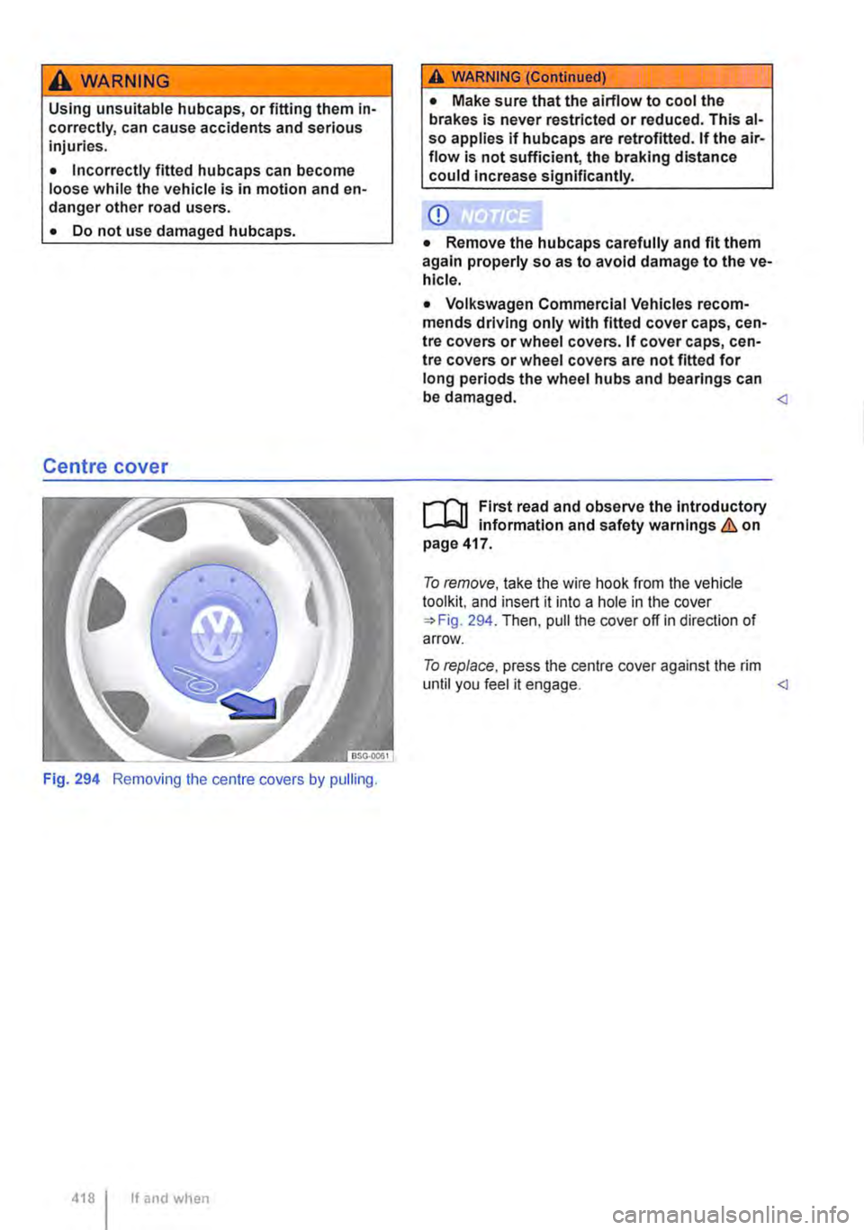
Fig. 294 Removing the centre covers by pulling.
418 I If and when
A WARNING (Continued)
• Make sure that the airflow to cool the brakes is never restricted or reduced. This al-so applies if hubcaps are retrofitted. If the air-flow is not sufficient, the braking distance could Increase significantly.
CD
• Remove the hubcaps carefully and fit them again properly so as to avoid damage to the ve-hicle.
• Volkswagen Commercial Vehicles recom-mends driving only with fitted cover caps, cen-tre covers or wheel covers. If cover caps, cen-tre covers or wheel covers are not fitted for long periods the wheel hubs and bearings can be damaged. <1
l"'""f'n First read and observe the introductory L-l=JI information and safety warnings & on page 417.
To remove, take the wire hook from the vehicle tool kit. and insert it into a hole in the cover =>Fig. 294. Then, pull the cover off in direction of arrow.
To replace, press the centre cover against the rim until you feel it engage.
Page 420 of 486
Changing a wheel
CllJ Introduction
This chapter contains information on the following subjects:
Preparations for changing a wheel . . . . . . . . . 420
Wheel bolts . . . . . . . . . . . . . . . . . . . 421
Lifting the vehicle with the jack . . . . . . . . . . . . 423
Changing a wheel . . . . . . . . . . . . . . . . . . . . . . . 424
After changing a wheel . . . . . . . . . . . . . 425
Some models are delivered without a factory-fitted jack or box spanner. If this is the case, the wheel should be changed by a qualified workshop.
The vehicle jack supplied with the vehicle is only designed for changing a wheel when one vehicle tyre is damaged and has to be replaced. Seek ex-pert assistance if both tyres on one side of the ve-hicle, both tyres on one axle, or all tyres are dam-aged.
Only change the wheel yourself when the car is parked in a safe place, you are familiar with the necessary steps and safety procedures and you have access to all the correct tools. Seek expert assistance if this is not the case.
Additional information and warnings:
• Exterior views =>page 5
• Vehicle key set =>page 36
• Tyre monitoring system =>page 318
• Wheels and tyres =>page 367
• In an emergency =>page 411
• Vehicle tool kit =>page 416
• Hubcaps =>page 417
Preparations for changing a wheel
1"1'11 First read and observe the introductory L-1o:.U information and safety warnings & on page 420.
Checklist
The following actions must always be carried out in the given order in preparation for changing the wheel=>&:
1. In the event of a flat tyre, park your vehicle on a firm and level surface at a safe dis-tance from the flow of traffic.
2. Apply the handbrake =>page 269.
420 I If and when
A wARNING
Changing a wheel can be dangerous, espe-cially when carried out at the side of a road. Please note the following steps in order to re-duce the risk of serious injuries:
• Stop the vehicle as soon as possible and when safe to do so. Park the vehicle at a safe distance from moving traffic in order to carry out the wheel change.
• All passengers and children in particular must be at a safe distance and away from your area of work during the wheel change.
• Switch on the hazard warning lights to warn other road users.
• Check that the surface the vehicle Is parked on Is level and firm. If necessary use a large, strong board or similar support for the vehicle jack.
• Only change the wheel yourself if you feel confident carrying out the procedure. If not, seek expert assistance.
• Always use suitable and undamaged tools to change the wheel.
• Always switch off the engine, apply the handbrake and move the selector lever to the position P or select a gear on a manual gear-box in order to reduce the risk of unintended vehicle movement.
• The wheel bolt tightening torque should be checked with a torque wrench immediately after changing a wheel.
4. Stop the engine and remove the key from the ignition =>page 257.
5. Manual gearbox: select a gear =>page 260.
6. Make sure all vehicle occupants exit the ve-hicle and move to safety, for instance be-hind the safety barrier.
7. Chock the wheel diagonally opposite the wheel being worked on with a stone or a similar object. ""
Page 421 of 486
Checklist (Continued)
8. VI/hen towing a trailer, unhitch the trailer from the vehicle and park it properly.
9. Remove any items of luggage from the lug-gage compartment.
10. Remove the spare wheel and vehicle tools from the vehicle.
11. Remove the hubcaps =>page 417.
Wheel bolts
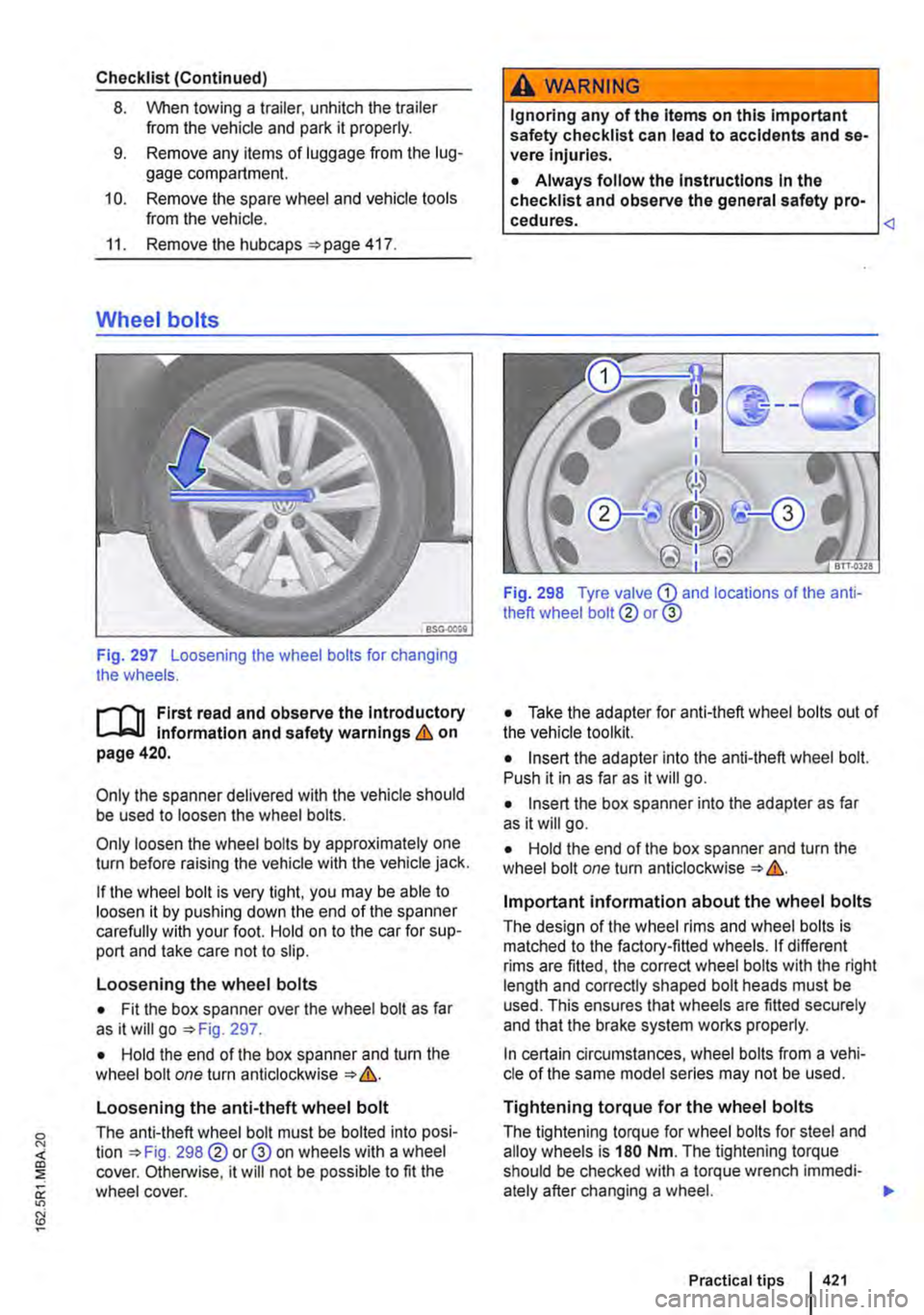
Fig. 297 Loosening the wheel bolts for changing the wheels.
r-"f"'n First read and observe the Introductory l.-J,:..LJ Information and safety warnings & on page420.
Only the spanner delivered with the vehicle should be used to loosen the wheel bolts.
Only loosen the wheel bolts by approximately one turn before raising the vehicle with the vehicle jack.
If the wheel bolt is very tight, you may be able to loosen it by pushing down the end of the spanner carefully with your foot. Hold on to the car for sup-port and take care not to slip.
Loosening the wheel bolts
• Fit the box spanner over the wheel bolt as far as it will go =>Fig. 297.
• Hold the end of the box spanner and turn the wheel bolt one turn anticlockwise => &.
Loosening the anti-theft wheel bolt
The anti-theft wheel bolt must be bolted into posi-tion =>Fig. 298@ or@ on wheels with a wheel cover. Otherwise, it will not be possible to fit the wheel cover.
A WARNING
Ignoring any of the Items on this Important safety checklist can lead to accidents and se-vere Injuries.
• Always follow the Instructions In the checklist and observe the general safety pro-
Fig. 298 Tyre valve G) and locations of the anti-theft wheel bolt@ or@
• Take the adapter for anti-theft wheel bolts out of the vehicle toolkit.
• Insert the adapter into the anti-theft wheel bolt. Push it in as far as it will go.
• Insert the box spanner into the adapter as far as it will go.
• Hold the end of the box spanner and turn the wheel bolt one turn anticlockwise => &.
Important information about the wheel bolts
The design of the wheel rims and wheel bolts is matched to the factory-fitted wheels. If different rims are fitted, the correct wheel bolts with the right length and correctly shaped bolt heads must be used. This ensures that wheels are fitted securely and that the brake system works properly.
In certain circumstances, wheel bolts from a vehi-cle of the same model series may not be used.
Tightening torque for the wheel bolts
The tightening torque for wheel bolts for steel and alloy wheels is 180 Nm. The tightening torque should be checked with a torque wrench immedi-ately after changing a wheel. .,.
Practical tips 421
Page 423 of 486

Lifting the vehicle with the jack
Fig. 299 Jacking points.
Fig. 300 On the left side of the vehicle: jack fitted at the front [AI and at the rear [ID.
r-('n First read and observe the introductory l.,...Jc.ll information and safety warnings & on page 420.
The jack may be applied only at the jacking points shown (markings on the body) '*Fig. 299.
• Front jacking point: web under the vehicle, at a distance approx. of 9 cm (dimension x) from the outer edge of the vehicle 300
• Rear jacking point: web under the vehicle, at a distance approx. of 15 cm (dimension y) from the outer edge of the vehicle 300 [ID.
The jack may be applied only on this rib.
Always use the jacking point closest to the wheel you are working on &.
Checklist
To ensure your own safety and the safety of your passengers, observe the following actions in the specified order &:
1. Find a firm and level surface suitable for lift-ing the vehicle.
2. Stop the engine, select a gear of the manual gearbox or move the selector lever of the dual clutch gearbox DSG® to position P '*page 260, and apply the handbrake 269.
3. Chock the wheel diagonally opposite using the collapsible chocks or other suitable ob-jects.
4. When towing a trailer, unhitch the trailer from the vehicle and park it properly.
5. Loosen the wheel bolts on the wheel that is being changed 421.
6. Find the jacking point under the vehicle '*Fig. 299 which is closest to the wheel that is being changed. .,.
Practical tips I 423
Page 426 of 486
• If the tyre pressure is very low or the tyres are flat.
• If the use-by date on the tyre filler bottle has ex-pired.
Additional information and warnings:
• Vehicle key set 36
• Seat functions, front 69
• Stowage 150
• Braking, stopping and parking =>page 269
• Wheels and tyres 367
• In an emergency 411
• Hubcaps 417
A WARNING
Using the breakdown set can be dangerous, especially if the tyres are inflated at the road-side. Please note the following points In or-der to reduce the risk of serious injuries:
• Stop the vehicle as soon as possible and when safe to do so. Park the vehicle at a safe distance from moving traffic in order to fill the tyre.
• Check that the surface the vehicle is parked on is level and firm.
• All passengers, and children in particular, must be at a safe distance and away from your area of work.
• Switch on the hazard warning lights to warn other road users.
• The breakdown set should only be used if you feel confident with carrying out the pro-cedure. If not, seek expert assistance.
Storing
rT'n First read and observe the introductory L-W.I information and safety warnings & on page 425.
Model
Multivan
California
426 I If and when
A WARNING (Continued)
• Tyres repaired with the breakdown set are intended for temporary, emergency use only. They should only be used until you can reach the nearest qualified workshop.
• Tyres that have been repaired using the breakdown set should be replaced as soon as possible.
• Sealant Is hazardous to health and must be washed off Immediately if it gets onto the skin.
• The breakdown set must be stored out of the reach of children.
• Never use a vehicle jack, even If it Is ap-proved for the vehicle.
• Always switch off the engine, apply the handbrake and move the selector lever to the position P or select a gear on a manual gear-box In order to reduce the risk of unintended vehicle movement.
A WARNING
Tyres that have been filled with sealant will not handle In the same way as a standard tyre.
• Never drive faster than 80 km/h (50 mph).
• Avoid full acceleration, sudden braking and fast driving through bends In the road.
• Drive for just 10 minutes at no more than 80 km/h (50 m ph) and then check the tyre.
Dispose of used or out-of-date sealant in ac-W cordance with legal requirements.
m You can get a new tyre filler bottle from a L!:J Volkswagen Commercial Vehicles dealership.
m Observe the separate instructions from the l!:J manufacturer of the breakdown set. <1
The breakdown set can be located in different pla-ces depending on the model.
Stowage
In the drawer in the 3-seat bench or in the drawer of the rear left single seat.
Behind the load-through hatch cover on the side of the bench seat/bed. <1
Page 427 of 486
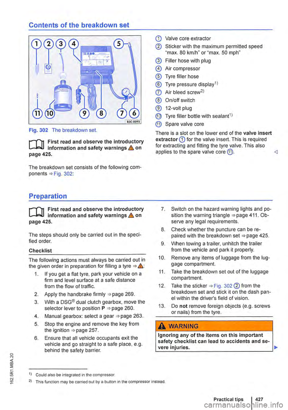
Contents of the breakdown set
Fig. 302 The breakdown set.
r--T'n First read and observe the introductory L-L::.U information and safety warnings & on page 425.
The breakdown set consists of the following com-ponents 302:
Preparation
r--T'n First read and observe the introductory L-L::.U information and safety warnings & on page 425.
The steps should only be carried out in the speci-fied order.
Checklist
The following actions must always be carried out in the given order in preparation for filling a tyre &:
1. If you get a flat tyre, park your vehicle on a firm and level surface at a safe distance from the flow of traffic.
2. Apply the handbrake firmly 269.
3. With a DSG® dual clutch gearbox, move the selector lever to position P 260.
4. Manual gearbox: select a gear 263.
5. Stop the engine and remove the key from the ignition 257.
6. Ensure that all vehicle occupants exit the vehicle and go straight to a safe place, e.g. behind the safety barrier.
1) Could also be integrated in the compressor.
CD Valve core extractor
® Sticker with the maximum permitted speed "max. 80 km/h" or "max. 50 mph"
@ Filler hose with plug
@ Air compressor
® Tyre filler hose
® Tyre pressure display 1 l
0 Air bleed screw2l
® On/off switch
® 12-volt plug
@ Tyre filler bottle with sealant1l
® Spare valve core
There is a slot on the lower end of the valve insert extractor CD for the valve insert. This is required for extracting and fitting the tyre valve. This also applies to the spare valve core @.
8. Check whether the puncture can be re-paired with the breakdown set 425.
9. When towing a trailer, unhitch the trailer from the vehicle and park it properly.
10. Remove any items of luggage from the lug-gage compartment.
11. Take the breakdown set out of the luggage compartment.
12. Take the sticker 302 ®from the breakdown set and stick it on the dash pan-el within the driver's field of vision.
13. Do not remove foreign objects (e.g. screws or nails) from the tyre.
A WARNING
Ignoring any of the items on this important safety checklist can lead to accidents and se-vere Injuries. ,..
2) This function may be carried out by a button in the compressor instead.
Practical tips 427
Page 433 of 486
A WARNING
Changing the bulb incorrectly can cause ac-cidents and serious Injuries.
• When working In the engine compartment, always read and observe the safety warnings =>page 350. The engine compartment of any motor vehicle Is a dangerous area. Serious Injuries can be sustained here.
• Halogen bulbs are pressurised and could explode when they are being changed.
• Only change the defective bulb once it has had time to cool down completely.
• Never change a bulb unless you are famili-ar with the procedure. If you are uncertain of what to do, the work should be carried out by a qualified workshop.
Indicator lamp
r--f"n First read and observe the introductory L-.J,:.lJ Information and safety warnings & on page 432.
Lit up Possible cause
A bulb in the exterior lighting has failed.
Several warning and indicator lamps will light up briefly as a functional check when the ignition is switched on. They will go out after a few seconds.
A WARNING
Failure to observe illuminated warning lamps and text messages can lead to your vehicle breaking down In traffic, and can cause acci-dent and serious Injury.
• Never ignore any illuminated warning lamps or text messages.
Information on changing bulbs
r--f"n First read and observe the introductory L-.J,:.lJ Information and safety warnings & on page 432.
A WARNING (Continued)
• Do not touch the glass part of the bulb with unprotected fingers. When the light is switched on, heat will cause fingerprints to evaporate on the bulb, which In turn will cause the reflector to dim.
• There are sharp-edged parts In the head-light housing In the engine compartment and on the tall light cluster housing. Protect your hands when changing bulbs.
CD
Damage to the electrical system can be caused by water entering the system if the rubber cov-ers or plastic caps on the headlight housing are not properly mounted after a bulb has been changed.
If bulbs of the exterior lighting fail, an indicator lamp lights up in the instrument cluster.
Solution
Change the defective bulb.
A WARNING (Continued)
• Stop the vehicle as soon as possible and when safe to do so.
CD
Failure to observe Illuminated indicator lamps and text messages can lead to your vehicle be-ing damaged.
m if an individual light emitting diode (LED) in W the exterior lighting fails, no warning is given. If all LEDs fail, this is indicated by the indicator lamp*··
Checklist
Always carry out the following actions for changing a bulb in the given order => &:
1. Park the vehicle on a firm and level surface at a safe distance from the flow of traffic.
2. Apply the handbrake firmly =>page 269. .,..
Practical tips I 433