Page 549 of 664
549
7 7-3. Do-it-yourself maintenance
Maintenance and care
●Back-up lights
●Outer foot lights (if equipped)
■Condensation build-up on the
inside of the lens
Temporary condensation build-up on
the inside of the light lens does not indi-
cate a malfunction. Contact any autho-
rized Toyota retailer or Toyota
authorized repairer, or any reliable
repairer for more information in the fol-
lowing situations:
●Large drops of water have built up on
the inside of the lens.
●Water has built up inside the light.
■When replacing an electronic com-
ponent, such as a lights, etc.
P.547
■Front turn signal lights
1Turn the bulb base counter-
clockwise.
2Remove the light bulb.3Install a new light bulb then
install the bulb base to the light
unit by inserting it and turning
the bulb base clockwise.
■Front fog lights
1To allow enough working space,
turn the steering wheel.
2Remove the screws.
Replacing light bulb
Page 550 of 664
5507-3. Do-it-yourself maintenance
3Remove the screws and clips,
partly remove the fender liner.
4Unplug the connector.
5Turn the bulb base counter-
clockwise.6Set the new light bulb.
Align the 3 tabs on the light bulb with
the mounting, and insert. Turn it clock-
wise to set.
7Set the connector.
Shake the bulb base gently to check
that it is not loose, turn the front fog
lights on once and visually confirm that
no light is leaking through the mount-
ing.
Page 551 of 664
551
7 7-3. Do-it-yourself maintenance
Maintenance and care
8Reinstall the fender liner.
9Reinstall the screws.
■Rear turn signal lights
1Open the back door and remove
the cover.2Remove the screws and remove
the light unit.
Remove the light unit by pulling it
directly backward from the rear of the
vehicle.
3Turn the bulb base counter-
clockwise.
4Remove the light bulb.
5Install a new light bulb then
install the bulb base to the light
Page 552 of 664
5527-3. Do-it-yourself maintenance
unit by inserting it and turning
the bulb base clockwise.
6Align the grooves on the light
unit with the claws, and insert
the light unit straight so that the
pin on the light unit fit into the
hole.
Confirm that the light unit is completely
secured.
7Reinstall the screws.
8Reinstall the cover.
■Back-up lights
1Open the back door and remove
the cover.
To prevent damage to the cover, pro-
tect the tip of the screwdriver with a rag.
2Turn the bulb base counter-
clockwise.
Remove the cord from the clip before
Page 553 of 664
553
7 7-3. Do-it-yourself maintenance
Maintenance and care
turning the bulb base.
3Remove the light bulb.
4Install a new light bulb.
5Install the bulb base to the light
unit by inserting it and turning
the bulb base clockwise.
Secure the cord with the clip back again after installing the bulb base.
6Reinstall the cover.
■Outer foot lights (if equipped)
1Press the upper part of the out-
side rear view mirror to tilt the
mirror face upward, and discon-
nect the four tabs behind the
mirror.
Pry the mirror out toward you, and dis-
connect two tabs at a time.
Work carefully, ensuring that you do not
Page 555 of 664
555
7 7-3. Do-it-yourself maintenance
Maintenance and care
damage the tabs.
6Turn the bulb base counter-
clockwise.
Remove the cord from the clip before
turning the bulb base.
7Remove the light bulb.
8Install a new light bulb then
install the bulb base to the light
unit by inserting it and turning
the bulb base clockwise.
Secure the cord with the clip back again
after installing the bulb base.
9Install the light unit.
Make sure that the two tabs of the light
unit are engaged securely, and install
Page 557 of 664

557
7
7-3. Do-it-yourself maintenance
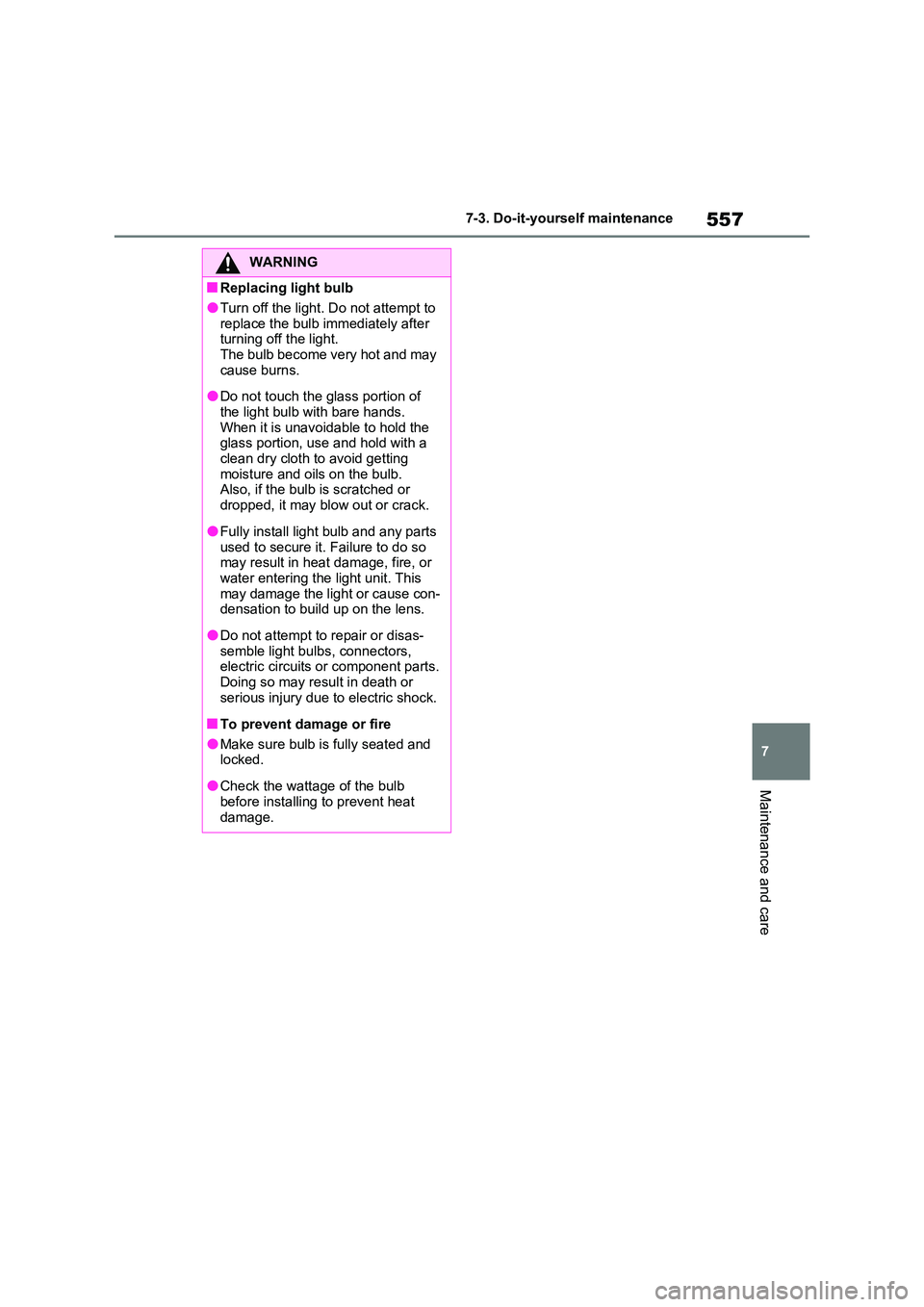
Maintenance and care
WARNING
■Replacing light bulb
●Turn off the light. Do not attempt to
replace the bulb immediately after turning off the light. The bulb become very hot and may
cause burns.
●Do not touch the glass portion of
the light bulb with bare hands. When it is unavoidable to hold the glass portion, use and hold with a
clean dry cloth to avoid getting moisture and oils on the bulb. Also, if the bulb is scratched or
dropped, it may blow out or crack.
●Fully install light bulb and any parts
used to secure it. Failure to do so may result in heat damage, fire, or water entering the light unit. This
may damage the light or cause con- densation to build up on the lens.
●Do not attempt to repair or disas-semble light bulbs, connectors, electric circuits or component parts.
Doing so may result in death or serious injury due to electric shock.
■To prevent damage or fire
●Make sure bulb is fully seated and locked.
●Check the wattage of the bulb before installing to prevent heat
damage.
Page 625 of 664

625
9 9-1. Specifications
Vehicle specifications
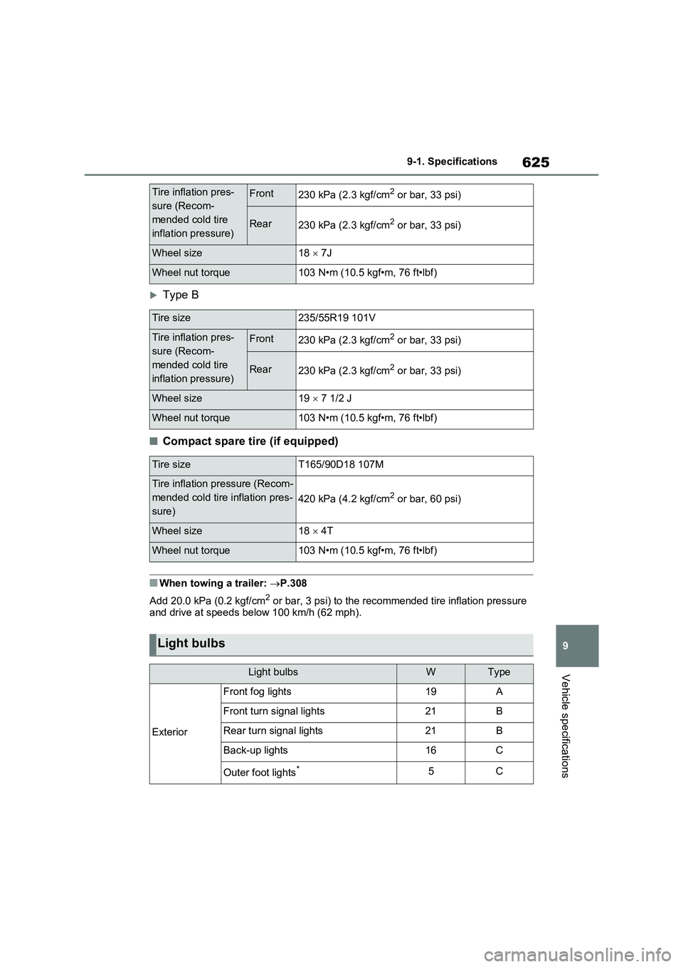
Type B
■Compact spare tire (if equipped)
■When towing a trailer: P.308
Add 20.0 kPa (0.2 kgf/cm
2 or bar, 3 psi) to the recommended tire inflation pressure
and drive at speeds below 100 km/h (62 mph).
Tire inflation pres-
sure (Recom-
mended cold tire
inflation pressure)Front230 kPa (2.3 kgf/cm2 or bar, 33 psi)
Rear230 kPa (2.3 kgf/cm2 or bar, 33 psi)
Wheel size18 7J
Wheel nut torque103 N•m (10.5 kgf•m, 76 ft•lbf)
Tire size235/55R19 101V
Tire inflation pres-
sure (Recom-
mended cold tire
inflation pressure)Front230 kPa (2.3 kgf/cm2 or bar, 33 psi)
Rear230 kPa (2.3 kgf/cm2 or bar, 33 psi)
Wheel size19 7 1/2 J
Wheel nut torque103 N•m (10.5 kgf•m, 76 ft•lbf)
Tire sizeT165/90D18 107M
Tire inflation pressure (Recom-
mended cold tire inflation pres-
sure)
420 kPa (4.2 kgf/cm2 or bar, 60 psi)
Wheel size18 4T
Wheel nut torque103 N•m (10.5 kgf•m, 76 ft•lbf)
Light bulbs
Light bulbsWType
Exterior
Front fog lights19A
Front turn signal lights21B
Rear turn signal lights21B
Back-up lights16C
Outer foot lights*5C