2011 SUBARU TRIBECA turn signal
[x] Cancel search: turn signalPage 156 of 422
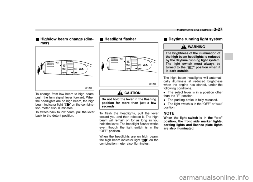
&High/low beam change (dim- mer)
To change from low beam to high beam,
push the turn signal lever forward. When
the headlights are on high beam, the high
beam indicator light “
”on the combina-
tion meter also illuminates.
To switch back to low beam, pull the lever
back to the detent position. &
Headlight flasher
CAUTION
Do not hold the lever in the flashing
position for more than just a fewseconds.
To flash the headlights, pull the lever
toward you and then release it. The high
beam will remain on for as long as you
hold the lever. The headlight flasher works
even though the light switch is in the“ OFF ”position.
When the headlights are on high beam,
the high beam indicator light “
”on the
combination meter also illuminates. &
Daytime running light system
WARNING
The brightness of the illumination of
the high beam headlights is reduced
by the daytime running light system.
The light switch must always be
turned to the “
”position when it
is dark outside.
The high beam headlights will automati-
cally illuminate at reduced brightness
when the engine has started, under the
following conditions. . The select lever is in a position other
than the “P ”position.
. The parking brake is fully released.
. The light switch is in the “OFF ”or “
”
position.
NOTE
When the light switch is in the “
”
position, the front side marker lights,
parking lights and license plate lights
are also illuminated. Instruments and controls
3-27
Page 157 of 422

3-28Instruments and controls
Turn signal lever
To activate the right turn signal, push the
turn signal lever up. To activate the left
turn signal, push the turn signal lever
down. When the turn is finished, the lever
will return automatically. If the lever does
not return after cornering, return the lever
to the neutral position by hand.
To signal a lane change, push the turn
signal lever up or down slightly and hold it
during the lane change. The turn signal
indicator lights will flash in the direction of
the turn or lane change. The lever will
return automatically to the neutral position
when you release it. Illumination brightness con- trol
When the light switch is in the
“OFF ”
position, you can adjust the brightness of
the instrument panel illumination for better
visibility.
The brightness of audio, air conditioner,
multi-function display (if equipped) and
instrument panel illumination automati-
cally dims when the light switch is in the“
” or “”position. You can adjust
brightness of the illumination for better
visibility.
To brighten, turn the control dial upward.
To darken, turn the control dial downward. NOTE
When the control dial is turned fully
upward, the illumination brightness
becomes the maximum and the auto-
matic dimming function does not work
at all.
Page 160 of 422
Parking light switch
The parking light switch operates regard-
less of the ignition switch position.
By pushing the front end of this switch,
following lights will illuminate. –Parking lights
– Front and rear side marker lights
– Tail lights
– License plate lights
To turn off, push the rear end of the
parking light switch.
Avoid leaving these lights on for a long
time because that will run down the
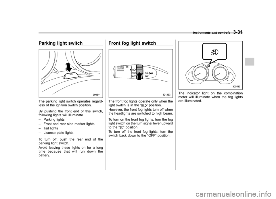
battery. Front fog light switchThe front fog lights operate only when the
light switch is in the
“”position.
However, the front fog lights turn off when
the headlights are switched to high beam.
To turn on the front fog lights, turn the fog
light switch on the turn signal lever upward
to the “
”position.
To turn off the front fog lights, turn the
switch back down to the “OFF ”position.
The indicator light on the combination
meter will illuminate when the fog lights
are illuminated. Instruments and controls
3-31
Page 195 of 422

5-8Audio
! XM
TMsatellite radio (for U.S.A. only)
XMTMis a continental U.S. based satellite
radio service, including music, news,
sports, talk and children ’s programming.
XM
TMprovides digital quality audio and
text information, including song title and
artist name. A service fee is required to
receive the XM
TMservice. For more
information, contact XMTMatwww.xmradio.com or call 1-800-
XMRADIO (1-800-967-2346). ! Satellite radio reception
Satellite radio signals are best received in
areas with a clear view of the open sky. In
areas where there are tall buildings, trees,
tunnels or other structures that may
obstruct the signal of the satellites, there
may be signal interruptions. Other circum-
stances that may result in signal loss
include driving near a wall, steep cliff or
hill, or driving on the lower level of a multi-
tiered road or inside a parking garage.
To help reduce this condition, satellite
radio providers have installed ground-
based repeaters in heavily populated
areas. However, you may still experience
reception problems in some areas. ! Displaying satellite radio ID of tuner
When you activate satellite radio, you
should have your satellite radio tuner ID ready because each tuner is identified by
its unique satellite radio tuner ID.
The satellite radio ID will be needed when
you activate satellite radio and receive
satellite radio customer support.
The satellite radio ID can be found on the
audio display by tuning the channel to
“0 ”.
Turn the “TUNE TRACK ”button (4) to
select the satellite radio channel. ! Band selection button
Push the “SAT ”button (1) when the radio
is off to turn on the radio.
Push the “SAT ”button when the radio is
on to select SAT1, SAT2 or SAT3 recep- tion. ! Channel selection
Press “
”of the “TUNE TRACK ”button
(4) to select the next channel and press “
” of the button to select the previous
channel.
Keep pressing “
”of the button to
change to the next channel continuously
and keep pressing “
”of the button to
change to the previous channel continu-
ously. ! Category selection
Press “
”or “”of the “SEEK FLDR ”
button (7) to display the current category. Press “
”again to select the next category, and press
“
”again to select
the previous category. ! Channel scan
Press the “SCAN ”button (8) to change the
radio to the SCAN mode. In this mode, the
radio scans through the channels until a
station is found. The radio will stop at the
station for 5 seconds while displaying the
channel number, after which scanning will
continue until the entire channel has been
scanned from the low end to the high end.
Also during the category selection, chan-
nel scan can be performed in that cate-
gory.
Press the “SCAN ”button again to cancel
the SCAN mode and to stop on any
displayed channel. ! Selecting preset channels
Presetting a channel with a preset button
(10) allows you to select that channel in a
single operation. Up to six, SAT1, SAT2
and SAT3 channels each may be preset. ! How to preset channels
1. Press the “SAT ”button (1) to select
SAT1, SAT2 and SAT3 reception.
2. Press the “SCAN ”button (8) or the
“ TUNE TRACK ”button (4) to select the
channel.
3. Press one of the preset buttons (10)
Page 206 of 422

!XMTMsatellite radio (for U.S.A. only)
XMTMis a continental U.S. based satellite
radio service, including music, news,
sports, talk and children ’s programming.
XM
TMprovides digital quality audio and
text information, including song title and
artist name. A service fee is required to
receive the XM
TMservice. For more
information, contact XMTMatwww.xmradio.com or call 1-800-
XMRADIO (1-800-967-2346). ! Satellite radio reception
Satellite radio signals are best received in
areas with a clear view of the open sky. In
areas where there are tall buildings, trees,
tunnels or other structures that may
obstruct the signal of the satellites, there
may be signal interruptions. Other circum-
stances that may result in signal loss
include driving near a wall, steep cliff or
hill, or driving on the lower level of a multi-
tiered road or inside a parking garage.
To help reduce this condition, satellite
radio providers have installed ground-
based repeaters in heavily populated
areas. However, you may still experience
reception problems in some areas. ! Displaying satellite radio ID of tuner
When you activate satellite radio, you
should have your satellite radio tuner ID ready because each tuner is identified by
its unique satellite radio tuner ID.
The satellite radio ID will be needed when
you activate satellite radio and receive
satellite radio customer support.
The satellite radio ID can be found on the
audio display by tuning the channel to
“0 ”.
Turn the “TUNE/TRACK ”button (4) to
select the satellite radio channel. ! Band selection button
Push the “SAT ”button (1) when the radio
is off to turn on the radio.
Push the “SAT ”button when the radio is
on to select SAT1, SAT2 or SAT3 recep- tion. ! Channel selection
Press “
”of the “TUNE TRACK ”button
(4) to select the next channel and press “
” of the button to select the previous
channel.
Keep pressing “
”of the button to
change to the next channel continuously
and keep pressing “
”of the button to
change to the previous channel continu-
ously. ! Category selection
Press “
”or “”of the “SEEK FLDR ”
button (7) to display the current category. Press “
”again to select the next category, and press
“
”again to select
the previous category. ! Channel scan
Press the “SCAN ”button (8) to change the
radio to the SCAN mode. In this mode, the
radio scans through the channels until a
station is found. The radio will stop at the
station for 5 seconds while displaying the
channel number, after which scanning will
continue until the entire channel has been
scanned from the low end to the high end.
Also during the category selection, chan-
nel scan can be performed in that cate-
gory.
Press the “SCAN ”button again to cancel
the SCAN mode and to stop on any
displayed channel. ! Selecting preset channels
Presetting a channel with a preset button
(10) allows you to select that channel in a
single operation. Up to six, SAT1, SAT2
and SAT3 channels each may be preset. ! How to preset channels
1. Press the “SAT ”button (1) to select
SAT1, SAT2 and SAT3 reception.
2. Press the “SCAN ”button (8) or the
“ TUNE TRACK ”button (4) to select the
channel.
3. Press one of the preset buttons (10) Audio
5-19
– CONTINUED –
Page 259 of 422
7-16Starting and operating
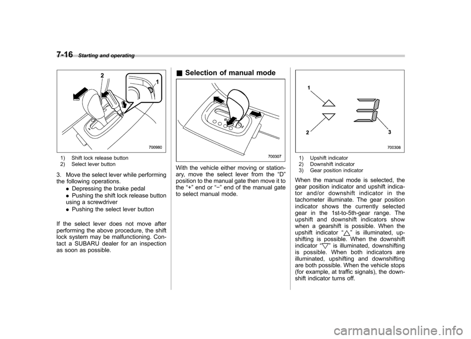
1) Shift lock release button
2) Select lever button
3. Move the select lever while performing
the following operations. .Depressing the brake pedal
. Pushing the shift lock release button
using a screwdriver . Pushing the select lever button
If the select lever does not move after
performing the above procedure, the shift
lock system may be malfunctioning. Con-
tact a SUBARU dealer for an inspection
as soon as possible. &
Selection of manual mode
With the vehicle either moving or station-
ary, move the select lever from the “D ”
position to the manual gate then move it tothe “+ ” end or “� ” end of the manual gate
to select manual mode.
1) Upshift indicator
2) Downshift indicator
3) Gear position indicator
When the manual mode is selected, the
gear position indicator and upshift indica-
tor and/or downshift indicator in the
tachometer illuminate. The gear position
indicator shows the currently selected
gear in the 1st-to-5th-gear range. The
upshift and downshift indicators show
when a gearshift is possible. When the
upshift indicator “
”is illuminated, up-
shifting is possible. When the downshift indicator “
”is illuminated, downshifting
is possible. When both indicators are
illuminated, upshifting and downshifting
are both possible. When the vehicle stops
(for example, at traffic signals), the down-
shift indicator turns off.
Page 271 of 422
7-28Starting and operating
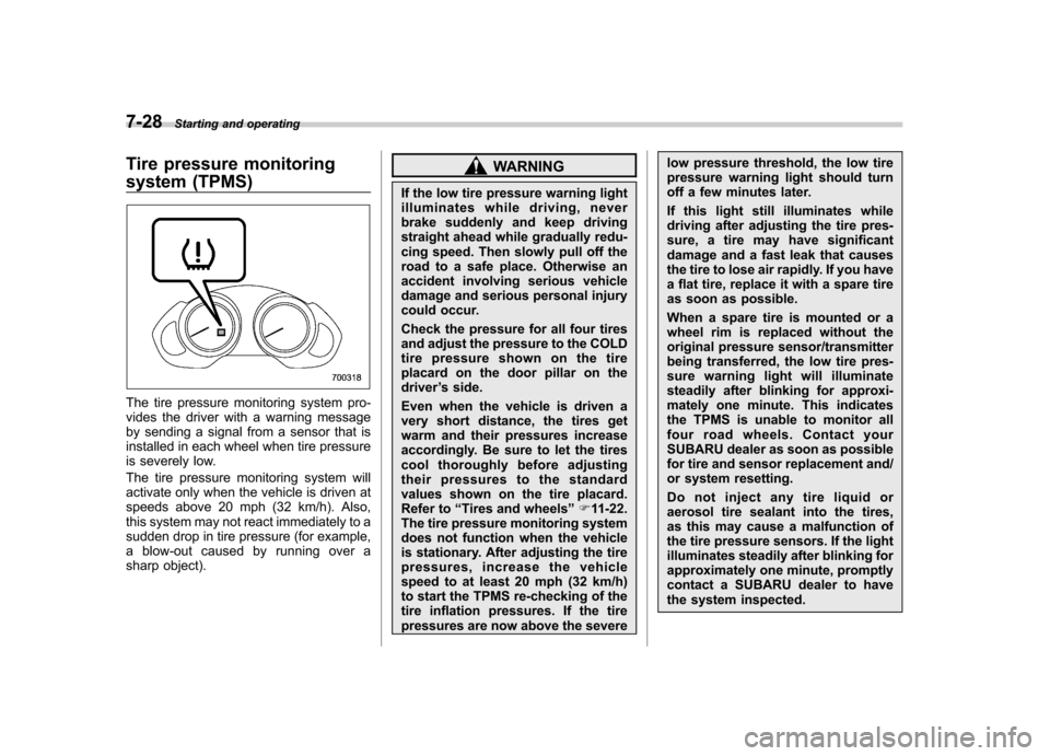
Tire pressure monitoring
system (TPMS)
The tire pressure monitoring system pro-
vides the driver with a warning message
by sending a signal from a sensor that is
installed in each wheel when tire pressure
is severely low.
The tire pressure monitoring system will
activate only when the vehicle is driven at
speeds above 20 mph (32 km/h). Also,
this system may not react immediately to a
sudden drop in tire pressure (for example,
a blow-out caused by running over a
sharp object).
WARNING
If the low tire pressure warning light
illuminates while driving, never
brake suddenly and keep driving
straight ahead while gradually redu-
cing speed. Then slowly pull off the
road to a safe place. Otherwise an
accident involving serious vehicle
damage and serious personal injury
could occur.
Check the pressure for all four tires
and adjust the pressure to the COLD
tire pressure shown on the tire
placard on the door pillar on thedriver ’s side.
Even when the vehicle is driven a
very short distance, the tires get
warm and their pressures increase
accordingly. Be sure to let the tires
cool thoroughly before adjusting
their pressures to the standard
values shown on the tire placard.
Refer to “Tires and wheels ”F 11-22.
The tire pressure monitoring system
does not function when the vehicle
is stationary. After adjusting the tire
pressures, increase the vehicle
speed to at least 20 mph (32 km/h)
to start the TPMS re-checking of the
tire inflation pressures. If the tire
pressures are now above the severe low pressure threshold, the low tire
pressure warning light should turn
off a few minutes later.
If this light still illuminates while
driving after adjusting the tire pres-
sure, a tire may have significant
damage and a fast leak that causes
the tire to lose air rapidly. If you have
a flat tire, replace it with a spare tire
as soon as possible.
When a spare tire is mounted or a
wheel rim is replaced without the
original pressure sensor/transmitter
being transferred, the low tire pres-
sure warning light will illuminate
steadily after blinking for approxi-
mately one minute. This indicates
the TPMS is unable to monitor all
four road wheels. Contact your
SUBARU dealer as soon as possible
for tire and sensor replacement and/
or system resetting.
Do not inject any tire liquid or
aerosol tire sealant into the tires,
as this may cause a malfunction of
the tire pressure sensors. If the light
illuminates steadily after blinking for
approximately one minute, promptly
contact a SUBARU dealer to have
the system inspected.
Page 296 of 422
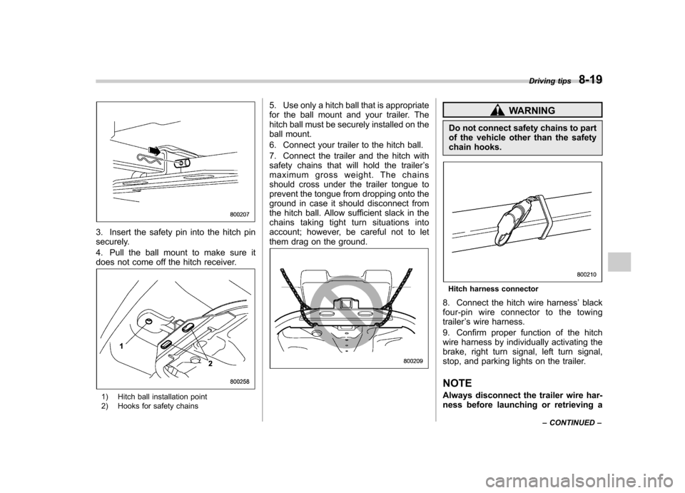
3. Insert the safety pin into the hitch pin
securely.
4. Pull the ball mount to make sure it
does not come off the hitch receiver.
1) Hitch ball installation point
2) Hooks for safety chains5. Use only a hitch ball that is appropriate
for the ball mount and your trailer. The
hitch ball must be securely installed on the
ball mount.
6. Connect your trailer to the hitch ball.
7. Connect the trailer and the hitch with
safety chains that will hold the trailer
’s
maximum gross weight. The chains
should cross under the trailer tongue to
prevent the tongue from dropping onto the
ground in case it should disconnect from
the hitch ball. Allow sufficient slack in the
chains taking tight turn situations into
account; however, be careful not to let
them drag on the ground.
WARNING
Do not connect safety chains to part
of the vehicle other than the safety
chain hooks.
Hitch harness connector
8. Connect the hitch wire harness ’black
four-pin wire connector to the towing trailer ’s wire harness.
9. Confirm proper function of the hitch
wire harness by individually activating the
brake, right turn signal, left turn signal,
stop, and parking lights on the trailer. NOTE
Always disconnect the trailer wire har-
ness before launching or retrieving a Driving tips
8-19
– CONTINUED –