2011 SUBARU TRIBECA fuel cap
[x] Cancel search: fuel capPage 289 of 422
8-12Driving tips
CAUTION
Do not carry spray cans, containers
with flammable or corrosive liquids
or any other dangerous items inside
the vehicle.
NOTE
For better fuel economy, do not carry
unneeded cargo. & Vehicle capacity weight
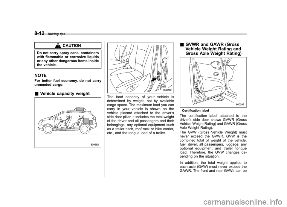
The load capacity of your vehicle is
determined by weight, not by available
cargo space. The maximum load you can
carry in your vehicle is shown on the
vehicle placard attached to the driver ’s
side door pillar. It includes the total weight
of the driver and all passengers and their
belongings, any optional equipment such
as a trailer hitch, roof rack or bike carrier,
etc., and the tongue load of a trailer. &
GVWR and GAWR (Gross
Vehicle Weight Rating and
Gross Axle Weight Rating)
Certification label
The certification label attached to the driver ’s side door shows GVWR (Gross
Vehicle Weight Rating) and GAWR (Gross
Axle Weight Rating).
The GVW (Gross Vehicle Weight) must
never exceed the GVWR. GVW is the
combined total of weight of the vehicle,
fuel, driver, all passengers, luggage, any
optional equipment and trailer tongue
load. Therefore, the GVW changes de-
pending on the situation.
In addition, the total weight applied to
each axle (GAW) must never exceed the
GAWR. The front and rear GAWs can be
Page 297 of 422
8-20Driving tips
watercraft. &When you do not tow a trailer
. Remove the ball mount from the hitch
receiver tube and insert the receiver cover
onto the hitch receiver tube. . Place the dust cap over the four-pin
connector of the hitch wire harness to
protect against possible damage. . Occasionally lubricate terminals of the
four-pin connector using the terminal grease. Trailer towing
Your vehicle is designed and intended to
be used primarily as a passenger-carrying
vehicle. Towing a trailer puts additional
loads on your vehicle
’s engine, drivetrain,
brakes, tires and suspension and has an
adverse effect on fuel economy.
If you do decide to tow a trailer, your safety
and satisfaction depend upon proper use
of correct equipment and cautious opera-
tion of your vehicle. Seek the advice of
your SUBARU dealer to assist you in
purchasing a hitch and other necessary
towing equipment appropriate for your
vehicle. In addition, be sure to follow the
instructions on correct installation and use
provided by the trailer and other towing
equipment manufacturers.
SUBARU assumes no responsibility for
injuries or vehicle damage that result from
trailer towing equipment, or from any
errors or omissions in the instructions
accompanying such equipment or for your
failure to follow the proper instructions.
& Warranties and maintenance
SUBARU warranties do not apply to
vehicle damage or malfunction caused
by trailer towing. If you use your vehicle to
tow a trailer, more frequent maintenance
will be required due to the additional load. (Refer to
“Maintenance schedule under
severe driving conditions ”in the “Warranty
and Maintenance Booklet ”.)
Under no circumstances should a trailer
be towed with a new vehicle or a vehicle
with any new powertrain component (en-
gine, transmission, differential, wheel
bearings, etc.) for the first 1,000 miles
(1,600 km) of driving.
& Maximum load limits
WARNING
Never exceed the maximum load
limits explained in the following.
Exceeding the maximum load limits
could cause personal injury and/or
vehicle damage.
CAUTION
. Adequate size trailer brakes are
required when the trailer and its
cargo exceed 1,000 lbs (453 kg)
total weight.
. Before towing a trailer, check the
trailer total weight, GVW, GAWs
and tongue load. Make sure the
load and its distribution in your
vehicle and trailer are accepta-
Page 340 of 422
7. Remove the oil filter with an oil filter wrench.
8. Clean the rubber seal seating area of
the bottom of engine and install the oil
filter by hand turning. Be careful not to
twist or damage the seal.
9. Tighten the oil filter by the amount
indicated in the following table after the
seal makes contact with the bottom ofengine.Oil filter color Part number Amount of ro-
tation
Black 15208AA031 3/4 rotation
CAUTION
. Never over tighten the oil filter
because that can result in an oil leak.
. Thoroughly wipe off any engine
oil that has spilled over the
exhaust pipe and/or under-cover.
If left unremoved, the oil could
catch fire.
10. Reinstall the cover under the oil filter.
11. Pour engine oil through the filler neck.
For the oil capacity guideline, refer to “ Engine oil ”F 12-4. The necessary quan-
tity of oil depends on the quantity of oil that has been drained. The quantity of drained
oil differs slightly depending on the tem-
perature of the oil and the time the oil is
left flowing out. After refilling the engine
with oil, therefore, you must use the level
gauge to confirm that the level is correct.
12. Start the engine and make sure that no
oil leaks appear around the filter
’s rubber
seal and drain plug.
13. Run the engine until it reaches the
normal operating temperature. Then stop
the engine and wait a few minutes to allow
the oil drain back. Check the oil level
again and if necessary, add more engineoil. & Recommended grade and viscosity
CAUTION
Use only engine oil with the recom-
mended grade and viscosity.
Refer to “Engine oil ”F 12-4.
NOTE
Engine oil viscosity (thickness) affects
fuel economy. Oils of lower viscosity
provide better fuel economy. However,
in hot weather, oil of higher viscosity is
required to properly lubricate the en- gine. &
Synthetic oil
You should use synthetic engine oil that
meets the same requirements given for
conventional engine oil. When using
synthetic oil, you must use oil of the same
classification, viscosity and grade shown
in this Owner ’s Manual. Refer to “Engine
oil ”F 12-4. Also, you must follow the oil
and filter changing intervals shown in the
Warranty and Maintenance booklet.
NOTE
Synthetic oil of the grade and viscosity
noted in chapter 12 is the required
engine oil for optimum engine perfor-
mance. Conventional oil may be used if
synthetic oil is unavailable. Maintenance and service
11-9
Page 341 of 422
11-10Maintenance and service
Cooling system
WARNING
Never attempt to remove the radia-
tor cap until the engine has been
shut off and has cooled down
completely. Since the coolant is
under pressure, you may suffer
serious burns from a spray of boil-
ing hot coolant when the cap isremoved.
CAUTION
. Vehicles are filled at the factory
with SUBARU Super Coolant that
does not require the first change
for 11 years/137,500 miles (11
years/220,000 km). This coolant
should not be mixed with any
other brand or type of coolant
during this period. Mixing with a
different coolant will reduce the
life of the coolant. Should it be
necessary to top off the coolant
for any reason, use only
SUBARU Super Coolant.
If the SUBARU Super Coolant is
diluted with another brand or
type, the maintenance interval is shortened to that of the mixingcoolant.
. Do not splash the engine coolant
over painted parts. The alcohol
contained in the engine coolant
may damage the paint surface.
& Hose and connections
Your vehicle employs an electric cooling
fan which is thermostatically controlled to
operate when the engine coolant reaches
a specific temperature.
If the radiator cooling fan does not operate
even when the engine coolant tempera-
ture gauge exceeds the normal operating
range, the cooling fan circuit may be
defective. Check the fuse and replace it
if necessary. If the fuse is not blown, have
the cooling system checked by your
SUBARU dealer.
If frequent addition of coolant is neces-
sary, there may be a leak in the engine
cooling system. It is recommended that
the cooling system and connections be
checked for leaks, damage, or looseness. &
Engine coolant
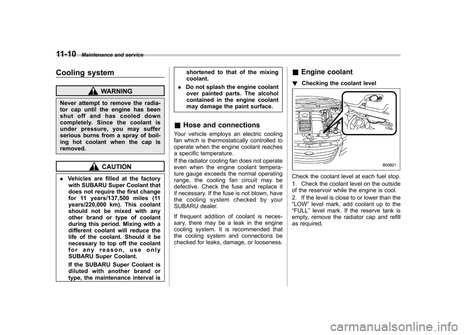
! Checking the coolant level
Check the coolant level at each fuel stop.
1. Check the coolant level on the outside
of the reservoir while the engine is cool.
2. If the level is close to or lower than the “LOW ”level mark, add coolant up to the
“ FULL ”level mark. If the reserve tank is
empty, remove the radiator cap and refill
as required.
Page 380 of 422
&Fuel
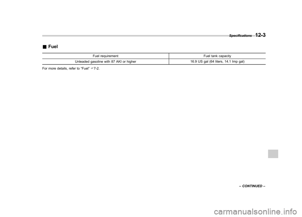
Fuel requirement Fuel tank capacity
Unleaded gasoline with 87 AKI or higher 16.9 US gal (64 liters, 14.1 Imp gal)
For more details, refer to “Fuel ”F 7-2. Specifications
12-3
– CONTINUED –
Page 399 of 422
13-6Consumer information and Reporting safety defects
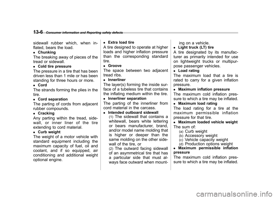
sidewall rubber which, when in-
flated, bears the load.. Chunking
The breaking away of pieces of the
tread or sidewall.. Cold tire pressure
The pressure in a tire that has been
driven less than 1 mile or has been
standing for three hours or more.. Cord
The strands forming the plies in the tire. . Cord separation
The parting of cords from adjacent
rubber compounds.. Cracking
Any parting within the tread, side-
wall, or inner liner of the tire
extending to cord material. . Curb weight
The weight of a motor vehicle with
standard equipment including the
maximum capacity of fuel, oil and
coolant, and if so equipped, air
conditioning and additional weight
optional engine. .
Extra load tire
A tire designed to operate at higher
loads and higher inflation pressure
than the corresponding standardtire. . Groove
The space between two adjacent
tread ribs.. Innerliner
The layer(s) forming the inside sur-
face of a tubeless tire that contains
the inflating medium within the tire. . Innerliner separation
The parting of the innerliner from
cord material in the carcass.. Intended outboard sidewall
(1) The sidewall that contains a
whitewall, bears white lettering
or bears manufacturer, brand,
and/or model name molding that
is higher or deeper than the
same molding on the other side-
wall of the tire, or (2) The outward facing sidewall
of an asymmetrical tire that has
a particular side that must al-
ways face outward when mount- ing on a vehicle.
. Light truck (LT) tire
A tire designated by its manufac-
turer as primarily intended for use
on lightweight trucks or multipur-
pose passenger vehicles. . Load rating
The maximum load that a tire is
rated to carry for a given inflationpressure.. Maximum inflation pressure
The maximum cold inflation pres-
sure to which a tire may be inflated.. Maximum load rating
The load rating for a tire at the
maximum permissible inflation
pressure for that tire.. Maximum loaded vehicle weight
The sum of: (a) Curb weight
(b) Accessory weight
(c) Vehicle capacity weight
(d) Production options weight
. Maximum permissible inflation
pressure
The maximum cold inflation pres-
sure to which a tire may be inflated.
Page 414 of 422
Active head restraint................................................. 1-6
Forward and backward adjustment ............................. 1-3
Head restraint adjustment ......................................... 1-5
Lumbar support ....................................................... 1-7
Memory function ...................................................... 1-4
Power seat .............................................................. 1-3
Reclining ................................................................. 1-3
Seat height adjustment ............................................. 1-4
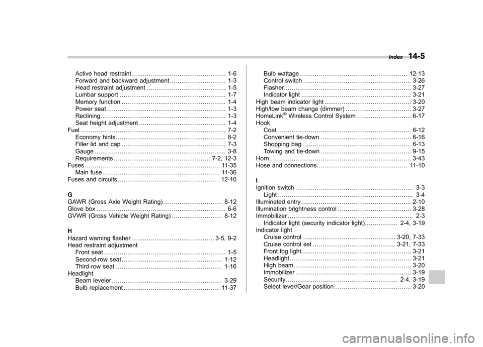
Fuel ........................................................................... 7-2
Economy hints ......................................................... 8-2
Filler lid and cap ...................................................... 7-3
Gauge .................................................................... 3-8
Requirements .................................................. 7-2, 12-3
Fuses ...................................................................... 11-35
Main fuse ............................................................. 11-36
Fuses and circuits .................................................... 12-10
G
GAWR (Gross Axle Weight Rating) .............................. 8-12
Glove box ................................................................... 6-6
GVWR (Gross Vehicle Weight Rating) .......................... 8-12
H
Hazard warning flasher ........................................... 3-5, 9-2
Head restraint adjustment Front seat ............................................................... 1-5
Second-row seat .................................................... 1-12
Third-row seat ....................................................... 1-16
Headlight Beam leveler ......................................................... 3-29
Bulb replacement .................................................. 11-37 Bulb wattage
........................................................ 12-13
Control switch ........................................................ 3-26
Flasher .................................................................. 3-27
Indicator light ......................................................... 3-21
High beam indicator light ............................................. 3-20
High/low beam change (dimmer) .................................. 3-27
HomeLink
®Wireless Control System ............................ 6-17
Hook Coat ..................................................................... 6-12
Convenient tie-down ............................................... 6-16
Shopping bag ........................................................ 6-13
Towing and tie-down ............................................... 9-15
Horn ......................................................................... 3-43
Hose and connections ............................................... 11-10
I
Ignition switch ............................................................. 3-3
Light ...................................................................... 3-4
Illuminated entry ......................................................... 2-10
Illumination brightness control ...................................... 3-28
Immobilizer ................................................................. 2-3
Indicator light (security indicator light) ................. 2-4, 3-19
Indicator light
Cruise control ................................................ 3-20, 7-33
Cruise control set ........................................... 3-21, 7-33
Front fog light ......................................................... 3-21
Headlight ............................................................... 3-21
High beam ............................................................. 3-20
Immobilizer ............................................................ 3-19
Security .......................................................... 2-4, 3-19
Select lever/Gear position ........................................ 3-20Index
14-5
Page 419 of 422
14-10Index
Weight.................................................................. 8-20
Traction Control system OFF indicator light .......................................... 3-18, 7-25
OFF switch ........................................................... 7-27
Trailer Connecting ............................................................ 8-18
Hitch ............................................................ 8-18, 8-23
Towing .................................................................. 8-20
Towing tips ............................................................ 8-26
Trip meter ................................................................... 3-7
Turn signal Indicator lights ....................................................... 3-20
Lever .................................................................... 3-28
U
Under-floor storage compartment ................................. 6-16
V
Valet mode ................................................................ 2-18
Vanity mirror ...................................................... 6-5, 11-44
Vehicle Capacity weight ..................................................... 8-12
Identification ........................................................ 12-16
Symbols .................................................................... 3
Vehicle Dynamics Control Operation indicator light .................................. 3-18, 7-25
System ................................................................. 7-23
Warning light ................................................. 3-18, 7-25
Ventilator .................................................................... 4-2 W
Warning and indicator lights
.......................................... 3-9
Warning chimes
Seatbelt. ........................................................ 1-18, 3-10
Warning light ABS.............................................................. 3-15, 7-21
All-Wheel Drive ...................................................... 3-18
AT OIL TEMP ......................................................... 3-13
Brake system ......................................................... 3-16
Charge .................................................................. 3-13
CHECK ENGINE .................................................... 3-12
Door open ............................................................. 3-17
Low fuel ......................................................... 3-8, 3-17
Low tire pressure .................................................... 3-14
Oil pressure ........................................................... 3-13
Rear differential oil temperature ................................ 3-14
Seatbelt. ........................................................ 1-18, 3-10
SRS airbag system ................................................. 3-11
Vehicle Dynamics Control ................................ 3-18, 7-25
Windshield washer fluid ........................................... 3-18
Warranties ..................................................................... 1
Warranties and maintenance ........................................ 8-20
Washing .................................................................... 10-2
Waxing and polishing .................................................. 10-3
Wear indicators ........................................................ 11-26
Wheel Alignment .............................................................. 12-9
Aluminum ............................................................ 11-28
Balance ............................................................... 11-26
Nut tightening torque ............................................... 12-8
Replacement. ....................................................... 11-28