2011 SUBARU IMPREZA WRX STI oil temperature
[x] Cancel search: oil temperaturePage 28 of 459
Black plate (26,1)
北米Model "A1110BE-C" EDITED: 2010/ 12/ 17
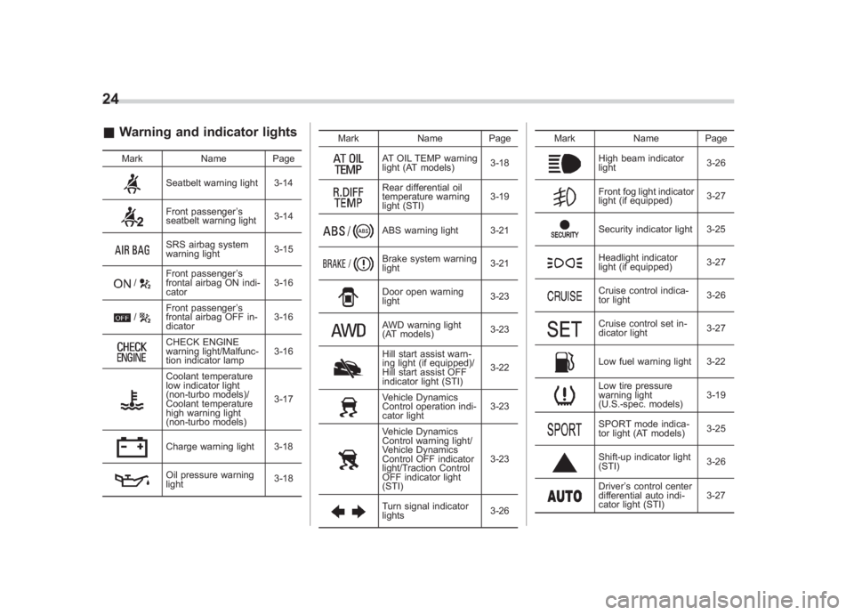
24& Warning and indicator lights
Mark Name Page
Seatbelt warning light 3-14Front passenger’s
seatbelt warning light 3-14SRS airbag system
warning light3-15
/
Front passenger
’s
frontal airbag ON indi-
cator 3-16
/
Front passenger
’s
frontal airbag OFF in-
dicator 3-16CHECK ENGINE
warning light/Malfunc-
tion indicator lamp3-16Coolant temperature
low indicator light
(non-turbo models)/
Coolant temperature
high warning light
(non-turbo models)3-17Charge warning light 3-18Oil pressure warning
light
3-18Mark Name Page
AT OIL TEMP warning
light (AT models)
3-18Rear differential oil
temperature warning
light (STI)3-19ABS warning light 3-21Brake system warning
light
3-21Door open warning
light3-23AWD warning light
(AT models)3-23Hill start assist warn-
ing light (if equipped)/
Hill start assist OFF
indicator light (STI)3-22Vehicle Dynamics
Control operation indi-
cator light
3-23Vehicle Dynamics
Control warning light/
Vehicle Dynamics
Control OFF indicator
light/Traction Control
OFF indicator light
(STI)3-23Turn signal indicator
lights
3-26Mark Name Page
High beam indicator
light
3-26Front fog light indicator
light (if equipped)3-27Security indicator light 3-25Headlight indicator
light (if equipped)3-27Cruise control indica-
tor light
3-26Cruise control set in-
dicator light3-27Low fuel warning light 3-22Low tire pressure
warning light
(U.S.-spec. models)3-19SPORT mode indica-
tor light (AT models)
3-25Shift-up indicator light
(STI)
3-26Driver
’s control center
differential auto indi-
cator light (STI) 3-27
Page 121 of 459
Black plate (5,1)
北米Model "A1110BE-C" EDITED: 2010/ 11/ 17
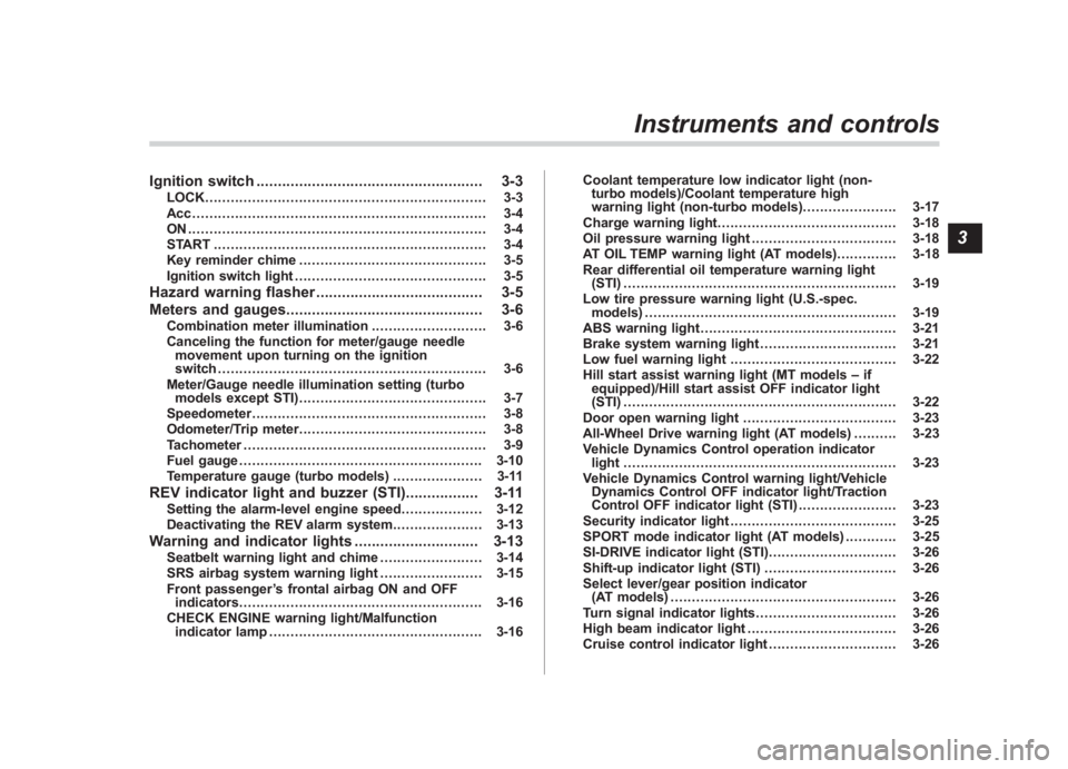
Ignition switch ..................................................... 3-3
LOCK.................................................................. 3-3
Acc..................................................................... 3-4
ON...................................................................... 3-4
START ................................................................ 3-4
Key reminder chime ............................................ 3-5
Ignition switch light ............................................. 3-5
Hazard warning flasher ....................................... 3-5
Meters and gauges. ............................................. 3-6
Combination meter illumination ........................... 3-6
Canceling the function for meter/gauge needle movement upon turning on the ignition
switch ............................................................... 3-6
Meter/Gauge needle illumination setting (turbo models except STI) ............................................ 3-7
Speedometer ....................................................... 3-8
Odometer/Trip meter ............................................ 3-8
Tachometer ......................................................... 3-9
Fuel gauge ......................................................... 3-10
Temperature gauge (turbo models) ..................... 3-11
REV indicator light and buzzer (STI). ................ 3-11
Setting the alarm-level engine speed ................... 3-12
Deactivating the REV alarm system ..................... 3-13
Warning and indicator lights............................. 3-13
Seatbelt warning light and chime ........................ 3-14
SRS airbag system warning light ........................ 3-15
Front passenger ’s frontal airbag ON and OFF
indicators ......................................................... 3-16
CHECK ENGINE warning light/Malfunction indicator lamp .................................................. 3-16 Coolant temperature low indicator light (non-
turbo models)/Coolant temperature high
warning light (non-turbo models) ...................... 3-17
Charge warning light .......................................... 3-18
Oil pressure warning light .................................. 3-18
AT OIL TEMP warning light (AT models) .............. 3-18
Rear differential oil temperature warning light (STI) ................................................................ 3-19
Low tire pressure warning light (U.S.-spec. models) ........................................................... 3-19
ABS warning light .............................................. 3-21
Brake system warning light ................................ 3-21
Low fuel warning light ....................................... 3-22
Hill start assist warning light (MT models –if
equipped)/Hill start assist OFF indicator light
(STI) ................................................................ 3-22
Door open warning light .................................... 3-23
All-Wheel Drive warning light (AT models) ..... ..... 3-23
Vehicle Dynamics Control operation indicator light ................................................................ 3-23
Vehicle Dynamics Control warning light/Vehicle Dynamics Control OFF indicator light/Traction
Control OFF indicator light (STI) ....................... 3-23
Security indicator light ....................................... 3-25
SPORT mode indicator light (AT models) ............ 3-25
SI-DRIVE indicator light (STI) .............................. 3-26
Shift-up indicator light (STI) ............................... 3-26
Select lever/gear position indicator (AT models) ..................................................... 3-26
Turn signal indicator lights ................................. 3-26
High beam indicator light ................................... 3-26
Cruise control indicator light .............................. 3-26
Instruments and controls
3
Page 133 of 459
Black plate (135,1)
北米Model "A1110BE-C" EDITED: 2010/ 12/ 17
to OFF, OFF to ON, or the vehicle starts
moving before the setting procedure is
finished.
. Setting the speed is impossible
when the vehicle is moving.
. The set engine speed may differ
from the engine speed shown by the
tachometer. Use the engine speed
shown by the tachometer as a rough
guide.
. If the setting operation is performed
with the engine switch turned off, the
REV indicator light turns off and the
setting operation is aborted when you
have stopped the setting operation for
approximately 10 seconds.
. If the setting operation is performed
with the engine switch turned off, the
REV indicator light turns off and the
setting operation is aborted when you
open and close the driver ’s door.& Deactivating the REV alarm
systemTo deactivate the REV indicator light and
buzzer functions of the REV alarm system,
set the thousands place of the alarm-level
engine speed to “–”.
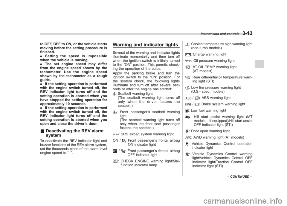
Warning and indicator lightsSeveral of the warning and indicator lights
illuminate momentarily and then turn off
when the ignition switch is initially turned
to the “ON”position. This permits check-
ing the operation of the bulbs.
Apply the parking brake and turn the
ignition switch to the “ON”position. For
the system check, the following lights
illuminate and turn off after several sec-
onds or after the engine has started:: Seatbelt warning light (The seatbelt warning light turns off
only when the driver fastens the
seatbelt.): Front passenger ’s seatbelt warning
light
(The seatbelt warning light turns off
only when the front seat passenger
fastens the seatbelt.): SRS airbag system warning light
ON /
: Front passenger ’s frontal airbag
ON indicator light
/
: Front passenger ’s frontal airbag
OFF indicator light
: CHECK ENGINE warning light/Mal- function indicator lamp
: Coolant temperature high warning light(non-turbo models): Charge warning light: Oil pressure warning light: AT OIL TEMP warning light (AT models): Rear differential oil temperature warn-ing light (STI): Low tire pressure warning light (U.S.- spec. models)/
: ABS warning light
/
: Brake system warning light
: Low fuel warning light: Hill start assist warning light (MT models –if equipped)/Hill start assist
OFF indicator light (STI): Door open warning light: AWD warning light (AT models): Vehicle Dynamics Control operation indicator light: Vehicle Dynamics Control warning light/Vehicle Dynamics Control OFF
indicator light/Traction Control OFF
indicator light (STI)
Instruments and controls
3-13
–CONTINUED –
3
Page 138 of 459
Black plate (140,1)
北米Model "A1110BE-C" EDITED: 2010/ 12/ 17
3-18
Instruments and controls
approximately 2 seconds when the igni-
tion switch is turned to the “ON”position.
After that, this indicator light/warning light
changes to BLUEand maintains illumina-
tion in BLUE. This BLUEilluminated light
turns off when the engine is warmed up
sufficiently.
If the engine coolant temperature in-
creases over the specified range, the
indicator light/warning light blinks in
RED . At this time, the engine is close to
overheating.
If the engine coolant temperature in-
creases further, the indicator light/warning
light illuminates in REDcontinuously. At
this time, the engine may be overheating.
When the indicator light/warning light
blinks in REDor illuminates in RED, safely
stop the vehicle as soon as possible, and
refer to the emergency steps to take in the
case of engine overheating. Refer to
“Engine overheating ”F 9-13. After that,
have the system checked by your nearest
SUBARU dealer.
Also, if the indicator light/warning light
often blinks in RED, the electrical system
may be malfunctioning. Contact your
SUBARU dealer for an inspection.
NOTEIf the engine is restarted after a certain
driving condition, this indicator light/
warning light may illuminate in RED.
However, this is not a malfunction if the
indicator light/warning light turns off
after a short time.&
Charge warning light
If this light illuminates when the engine is
running, it may indicate that the charging
system is not working properly.
If the light illuminates while driving or does
not turn off after the engine starts, stop the
engine at the first safe opportunity and
check the alternator belt. If the belt is
loose, broken or if the belt is in good
condition but the light remains illuminated,
contact your nearest SUBARU dealer
immediately.&
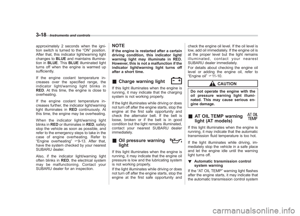
Oil pressure warning
light
If this light illuminates when the engine is
running, it may indicate that the engine oil
pressure is low and the lubricating system
is not working properly.
If the light illuminates while driving or does
not turn off after the engine starts, stop the
engine at the first safe opportunity and check the engine oil level. If the oil level is
low, add oil immediately. If the engine oil is
at the proper level but the light remains
illuminated, contact your nearest
SUBARU dealer immediately.
For details about checking the engine oil
level or adding the engine oil, refer to
“Engine oil
”F 11-10.
CAUTION
Do not operate the engine with the
oil pressure warning light illumi-
nated. This may cause serious en-
gine damage.&
AT OIL TEMP warning
light (AT models)
If this light illuminates when the engine is
running, it may indicate that the automatic
transmission fluid temperature is too hot.
If the light illuminates while driving, im-
mediately stop the vehicle in a safe place
and let the engine idle until the warning
light turns off.
! Automatic transmission control
system warning
If the “AT OIL TEMP ”warning light flashes
after the engine starts, it may indicate that
the automatic transmission control system
Page 139 of 459
Black plate (141,1)
北米Model "A1110BE-C" EDITED: 2010/ 12/ 17
is not working properly. Contact your
nearest SUBARU dealer for service im-
mediately.&
Rear differential oil
temperature warning
light (STI)
CAUTION
Reduce vehicle speed and park the
vehicle in a safe place as soon as
possible if the R.DIFF TEMP light
illuminates. Continued driving with
this light illuminated can damage
the rear differential and other parts
of the powertrain.
If this light illuminates when the engine is
running, it may indicate that the rear
differential oil temperature is too hot.
At this time, the driver ’s control center
differential will automatically cancel the
current torque-distribution ratio setting and
adopt its minimum ratio.
If the light illuminates while driving, reduce
vehicle speed and stop the vehicle at the
nearest safe place. Park the vehicle for
several minutes. After the light turns off,
you can start driving.
If the light does not turn off, contact the
nearest SUBARU dealer for service.
NOTE. If the tire pressures are not correct
and/or the tires are not all the same
size and brand, the rear differential will
be heavily loaded when the vehicle is
driven, resulting in an abnormally high
oil temperature.
. The rear differential oil will deterio-
rate if its temperature increases en-
ough for the rear differential oil tem-
perature warning light to illuminate. It is
advisable to have the rear differential
oil replaced as soon as possible.&
Low tire pressure
warning light (U.S.-spec.
models)
When the ignition switch is turned to the
“ON ”position, the low tire pressure warn-
ing light will illuminate for approximately 2
seconds to check that the tire pressure
monitoring system (TPMS) is functioning
properly. If there is no problem and all tires
are properly inflated, the light will turn off.
Each tire, including the spare (if provided),
should be checked monthly when cold
and inflated to the inflation pressure
recommended by the vehicle manufac-
turer on the vehicle placard or tire inflation
pressure label. (If your vehicle has tires of
a different size than the size indicated on the vehicle placard or tire inflation pres-
sure label, you should determine the
proper tire inflation pressure for those
tires.)
As an added safety feature, your vehicle
has been equipped with a tire pressure
monitoring system (TPMS) that illuminates
a low tire pressure telltale when one or
more of your tires is significantly under-
inflated. Accordingly, when the low tire
pressure telltale illuminates, you should
stop and check your tires as soon as
possible, and inflate them to the proper
pressure. Driving on a significantly under-
inflated tire causes the tire to overheat and
can lead to tire failure. Under-inflation also
reduces fuel efficiency and tire tread life,
and may affect the vehicle
’s handling and
stopping ability.
Please note that the TPMS is not a
substitute for proper tire maintenance,
and it is the driver ’s responsibility to
maintain correct tire pressure, even if
under-inflation has not reached the level
to trigger illumination of the TPMS low tire
pressure telltale.
Your vehicle has also been equipped with
a TPMS malfunction indicator to indicate
when the system is not operating properly.
The TPMS malfunction indicator is com-
bined with the low tire pressure telltale.
When the system detects a malfunction,
Instruments and controls
3-19
– CONTINUED –
3
Page 173 of 459
Black plate (7,1)
北米Model "A1110BE-C" EDITED: 2010/ 11/ 17
Ventilator .............................................................. 4-2
Airflow selection ................................................. 4-2
Center and side ventilators .................................. 4-3
Manual climate control system
(if equipped) ..................................................... 4-3
Control panel ...................................................... 4-3
Heater operation ................................................. 4-5
Air conditioner operation ..................................... 4-7
Automatic climate control system
(if equipped) ..................................................... 4-8
Control panel ...................................................... 4-8
To use as full-automatic climate control system .............................................................. 4-8
To use as semi-automatic climate control system .............................................................. 4-8
Fan speed control dial ......................................... 4-9
Temperature control dial ...................................... 4-9
Airflow control dial .............................................. 4-9
Air inlet selection button .................................... 4-10 Air conditioner button
........................................ 4-11
Temperature sensors ......................................... 4-11
Operating tips for heater and air
conditioner ...................................................... 4-12
Cleaning ventilation grille ................................... 4-12
Efficient cooling after parking in direct sunlight ........................................................... 4-12
Lubrication oil circulation in the refrigerant circuit .............................................................. 4-12
Checking air conditioning system before summer season ............................................................ 4-12
Cooling and dehumidifying in high humidity and low temperature weather conditions ................. 4-12
Air conditioner compressor shut-off when engine is heavily loaded .............................................. 4-13
Refrigerant for your climate control system ... ..... 4-13
Air filtration system........................................... 4-13
Replacing an air filter ......................................... 4-13
Climate control
4
Page 184 of 459
Black plate (186,1)
北米Model "A1110BE-C" EDITED: 2010/ 12/ 17
4-12
Climate control
properly and become damaged, the sys-
tem may not be able to control the interior
temperature correctly. To avoid damaging
the sensors, observe the following pre-
cautions.
– Do not subject the sensors to impact.
– Keep water away from the sensors.
– Do not cover the sensors.
The sensors are located as follows.
– Solar sensor: beside the windshield
defroster grille.
– Interior air temperature sensor: near
the ignition switch.
– Outside temperature sensor: behind
the front grille.
Operating tips for heater and
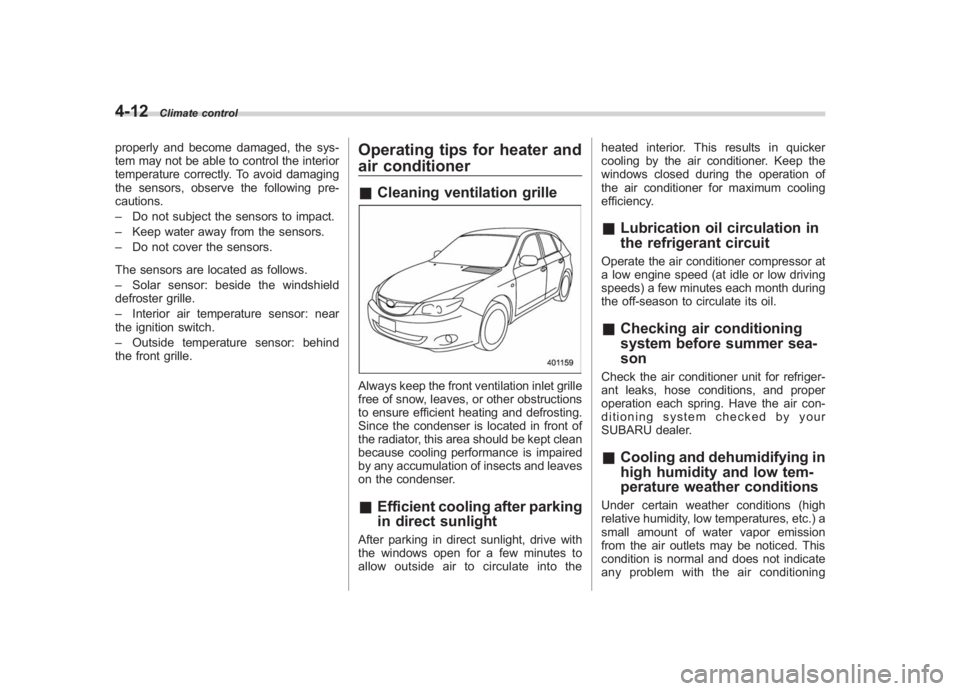
air conditioner& Cleaning ventilation grilleAlways keep the front ventilation inlet grille
free of snow, leaves, or other obstructions
to ensure efficient heating and defrosting.
Since the condenser is located in front of
the radiator, this area should be kept clean
because cooling performance is impaired
by any accumulation of insects and leaves
on the condenser.&Efficient cooling after parking
in direct sunlightAfter parking in direct sunlight, drive with
the windows open for a few minutes to
allow outside air to circulate into the heated interior. This results in quicker
cooling by the air conditioner. Keep the
windows closed during the operation of
the air conditioner for maximum cooling
efficiency.
&
Lubrication oil circulation in
the refrigerant circuitOperate the air conditioner compressor at
a low engine speed (at idle or low driving
speeds) a few minutes each month during
the off-season to circulate its oil.&Checking air conditioning
system before summer sea-
sonCheck the air conditioner unit for refriger-
ant leaks, hose conditions, and proper
operation each spring. Have the air con-
ditioning system checked by your
SUBARU dealer.&Cooling and dehumidifying in
high humidity and low tem-
perature weather conditionsUnder certain weather conditions (high
relative humidity, low temperatures, etc.) a
small amount of water vapor emission
from the air outlets may be noticed. This
condition is normal and does not indicate
any problem with the air conditioning
Page 290 of 459

Black plate (294,1)
北米Model "A1110BE-C" EDITED: 2010/ 12/ 17
7-26
Starting and operating
& Selection of manual mode
NOTEPlease read the following points care-
fully and bear them in mind when using
the manual mode.
. If you attempt to shift down when
the engine speed is too high, i.e., when
a downshift would push the tachometer
needle beyond the red zone, beeps will
be emitted to warn you that the down-
shift is not possible.
. If you attempt to shift up when the
vehicle speed is too low, the transmis-
sion will not respond.
. You can perform a skip-shift (for
example, from 4th to 2nd) by operating
the select lever twice in rapid succes-
sion.
. The transmission automatically se-
lects 1st gear when the vehicle stops
moving.
. If the temperature of the automatic
transmission fluid becomes too high,
the “AT OIL TEMP ”warning light will
illuminate and upshifts to 4th gear will
not be possible. Immediately stop the
vehicle in a safe place and let the
engine idle until the warning light turns
off.
With the vehicle either moving or station-
ary, move the select lever from the “D”
position to the manual gate then move it to
the “+”end or “�”end of the manual gate
to select manual mode.
1) Upshift indicator
2) Downshift indicator
3) Gear position indicatorWhen the manual mode is selected, the
gear position indicator and upshift indica-
tor and/or downshift indicator on the
combination meter illuminate. The gear
position indicator shows the currently
selected gear in the 1st-to-4th-gear range.
The upshift and downshift indicators show
when a gear shift is possible. When the
upshift indicator “
”is illuminated, up-
shifting is possible. When the downshift
indicator “
”is illuminated, downshifting
is possible. When both indicators are
illuminated, upshifting and downshifting
are both possible. When the vehicle stops
(for example, at traffic signals), the down-
shift indicator turns off.