2011 SUBARU IMPREZA WRX STI sensor
[x] Cancel search: sensorPage 89 of 459
Black plate (87,1)
北米Model "A1110BE-C" EDITED: 2010/ 12/ 17
& SRS airbag system servicing
WARNING
. When discarding an airbag mod-
ule or scrapping the entire vehi-
cle damaged by a collision, con-
sult your SUBARU dealer.
. The SRS airbag has no user-
serviceable parts. Do not use
electrical test equipment on any
circuit related to the SRS airbag
system. For required servicing of
the SRS airbag, consult your
nearest SUBARU dealer. Tamper-
ing with or disconnecting the
system ’s wiring could result in
accidental inflation of the SRS
airbag or could make the system
inoperative, which may result in
serious injury.
CAUTION
If you need service or repair in areas
indicated in the following list, have
the work performed by an author-
ized SUBARU dealer. The SRS air-
bag control module, impact sensors
and airbag modules are stored in
these areas. .
Under the center console
. On both the right and left sides at
the front of the vehicle
. Steering wheel and column and
nearby areas
. Top of the dashboard on front
passenger ’s side and nearby
areas
. Each front seat and nearby area
. Inside each center pillar
. In each roof side (from the front
pillar to a point over the rear seat)
. Between the rear seat cushion
and rear wheel house on each
side
. Under the rear center seat
In the event that the SRS airbag is
deployed, replacement of the system
should be performed only by an author-
ized SUBARU dealer. When the compo-
nents of the SRS airbag system are
replaced, use only genuine SUBARU
parts.
NOTEIn the following cases, contact your
SUBARU dealer as soon as possible.
. The front part of the vehicle was
involved in an accident in which only the driver
’s SRS frontal airbag or both
driver ’s and front passenger ’sSRS
frontal airbags did not deploy.
. The pad of the steering wheel, the
cover over the front passenger ’s SRS
frontal airbag, or either roof side (from
the front pillar to a point over the rear
seat) is scratched, cracked, or other-
wise damaged.
. Center pillar, rear wheel house or
rear sub frame, or an area near these
parts, was involved in an accident in
which the SRS side airbag and SRS
curtain airbag did not deploy.
. The fabric or leather of either front
seatback is cut, frayed, or otherwise
damaged.
. The rear part of the vehicle was
involved in an accident in which no
SRS airbag was deployed.
& Precautions against vehicle
modification
WARNING
To avoid accidental activation of the
system or rendering the system
inoperative, which may result in
serious injury, no modifications
should be made to any components
or wiring of the SRS airbag system.Seat, seatbelt and SRS airbags
1-57
–CONTINUED –
1
Page 91 of 459
Black plate (3,1)
北米Model "A1110BE-C" EDITED: 2010/ 11/ 17
Keys ..................................................................... 2-2
Key number plate ................................................ 2-2
Immobilizer.......................................................... 2-2
Security ID plate .................................................. 2-3
Security indicator light ........................................ 2-3
Key replacement ................................................. 2-3
Door locks........................................................... 2-4
Locking and unlocking from the outside .. ............ 2-4
Locking and unlocking from the inside ................ 2-5
Battery drainage prevention function ................... 2-5
Power door locking switches............................. 2-6
Key lock-in prevention function ........................... 2-7
Remote keyless entry system............................ 2-8
Locking the doors............................................... 2-9
Unlocking the doors ............................................ 2-9
Opening the trunk lid/unlocking rear gate ........... 2-10
Vehicle finder function ........................................ 2-10
Sounding a panic alarm ...................................... 2-10
Selecting audible signal operation ...................... 2-11
Replacing the battery ......................................... 2-11
Replacing lost transmitters ................................. 2-12
Alarm system..................................................... 2-16
System operation ............................................... 2-16
Activating and deactivating the alarm system ..... 2-16
If you have accidentally triggered the alarm system ............................................................ 2-17
Arming the system ............................................ 2-17
Disarming the system ........................................ 2-19
Valet mode ........................................................ 2-19
Passive arming .................................................. 2-19
Tripped sensor identification .............................. 2-20
Shock sensors (dealer option).. .......................... 2-20
Child safety locks.............................................. 2-21
Windows ............................................................. 2-21
Power windows ................................................. 2-21
Trunk lid (4-door) ............................................... 2-25
To open and close the trunk lid from outside . ..... 2-25
To open the trunk lid from inside. ....................... 2-25
To lock and unlock the trunk lid release lever ................................................................ 2-25
Internal trunk lid release handle ......................... 2-25
Rear gate (5-door).............................................. 2-27
Moonroof (if equipped) ...................................... 2-29
Moonroof switches............................................ 2-29
Sun shade ......................................................... 2-30
Keys and doors
2
Page 106 of 459
Black plate (106,1)
北米Model "A1110BE-C" EDITED: 2010/ 12/ 17
2-16
Keys and doors
Alarm systemThe alarm system helps to protect your
vehicle and valuables from theft. The horn
sounds and the turn signal lights flash if
someone attempts to break into your
vehicle. The starter motor is also inter-
rupted to prevent starting the vehicle
without a key.
The system can be armed and disarmed
with the remote transmitter.
The system does not operate when the
key is inserted into the ignition switch.
Your vehicle’ s alarm system has been set
for activation at the time of shipment from
the factory. You can set the system for
deactivation yourself or have it done by
your SUBARU dealer.& System operationThe alarm system will sound the following
alarms when triggered.
. The vehicle’ s horn will sound for 30
seconds.
. The turn signal lights will flash for 30
seconds.
If any of the doors or the rear gate/trunk lid
remains open after the 30-second period,
the horn will continue to sound for a
maximum of 3 minutes. If the door or the rear gate/trunk lid is closed while the horn
is sounding, the horn will stop sounding
with a delay of up to 30 seconds.
The alarm is triggered by:
.
Opening any of the doors, the rear gate
or trunk lid
. Physical impact to the vehicle, such as
forced entry (only models with shock
sensors (dealer option))
NOTEThe alarm system can be set to trigger
the illumination of the following interior
lights.
. Dome light (illuminates only when
the dome light switch is in the “DOOR ”
position)
. Map lights (models with moonroof)
The notifications regarding the dome
light and the map lights are deactivated
as the factory setting. A SUBARU
dealer can activate the system. Contact
your SUBARU dealer for details.& Activating and deactivating
the alarm systemTo change the setting of your vehicle’ s
alarm system for activation or deactiva-
tion, do the following.
1. Disarm the alarm system. Refer to “Disarming the system
”F 2-19.
2. Sit in the driver ’s seat and shut all
doors (and the rear gate if your vehicle is a
5-door).
3. Turn the ignition switch to the “ON”
position.
4. Hold down the REAR (UNLOCK) side
of the driver ’s power door locking switch,
open the driver ’s door within the following
1 second, and wait 10 seconds without
releasing the switch. The setting will then
be changed as follows.
If the system was previously activated:
The odometer/trip meter screen displays
“ AL oF ”and the horn sounds twice,
indicating that the system is now deacti-
vated.
If the system was previously deacti-
vated:
The odometer/trip meter screen displays
“ AL on” and the horn sounds once,
indicating that the system is now acti-
vated.
NOTEYou may have the above setting
change done by your SUBARU dealer.
Page 110 of 459
Black plate (110,1)
北米Model "A1110BE-C" EDITED: 2010/ 12/ 17
2-20
Keys and doors
“LOCK” position and remove the key from
the ignition switch.
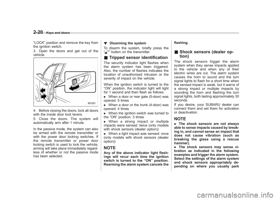
3. Open the doors and get out of the
vehicle.4. Before closing the doors, lock all doors
with the inside door lock levers.
5. Close the doors. The system will
automatically arm after 1 minute.
In the passive mode, the system can also
be armed with the remote transmitter or
with the power door locking switches. If
the remote transmitter or power door
locking switch is used to lock the vehicle,
arming will take place immediately regard-
less of whether or not the passive mode
has been selected. !
Disarming the system
To disarm the system, briefly press the
“
” button on the transmitter.
& Tripped sensor identificationThe security indicator light flashes when
the alarm system has been triggered.
Also, the number of flashes indicates the
location of unauthorized intrusion or the
severity of impact on the vehicle.
When the ignition switch is turned to the
“ON ”position, the indicator light will light
for 1 second and then flash as follows.
. When a door or rear gate (5-door) was
opened: 5 times
. When a door or the trunk (4-door) was
opened: 4 times
. When the ignition switch was turned to
the “ON ”position: 3 times
. When a strong impact or multiple
impacts were sensed: twice (only models
with shock sensors (dealer option))
. When a light impact was sensed: once
(only models with shock sensors (dealer
option))NOTEAny of the above indicator light flash-
ings will recur each time the ignition
switch is turned to the “ON ”position.
Rearming the alarm system cancels the flashing.
&
Shock sensors (dealer op-
tion)The shock sensors trigger the alarm
system when they sense impacts applied
to the vehicle and when any of their
electric wires are cut. The alarm system
causes the horn to sound and the turn
signal lights to flash for a short time when
the sensed impact is weak, but it warns of
a strong impact or multiple impacts by
sounding the horn and flashing the turn
signal lights, both lasting approximately 30
seconds.
If you desire, your SUBARU dealer can
connect them and set them for activation
or deactivation.NOTE. The shock sensors are not always
able to sense impacts caused by break-
ing in, and cannot sense an impact that
does not cause vibration (such as
breaking the glass using a rescue
hammer).
. The shock sensors may sense vi-
bration as indicated in the following
examples and trigger the alarm system.
Select the settings of the alarm system
and shock sensors appropriately de-
pending on where you usually park
Page 111 of 459
Black plate (111,1)
北米Model "A1110BE-C" EDITED: 2010/ 12/ 17
your vehicle.
Examples:
–Vibration from a construction site
– Vibration in a multistory car park
– Vibration from trains
. You can have the sensitivity of the
shock sensors adjusted to your pre-
ference by your SUBARU dealer.
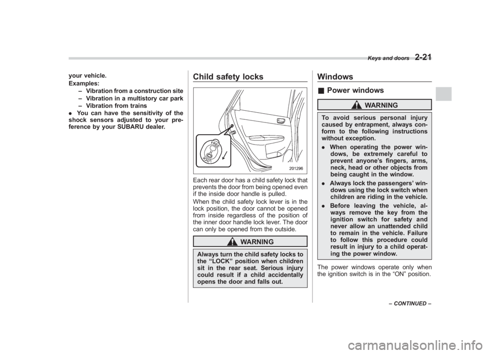
Child safety locksEach rear door has a child safety lock that
prevents the door from being opened even
if the inside door handle is pulled.
When the child safety lock lever is in the
lock position, the door cannot be opened
from inside regardless of the position of
the inner door handle lock lever. The door
can only be opened from the outside.
WARNING
Always turn the child safety locks to
the “LOCK ”position when children
sit in the rear seat. Serious injury
could result if a child accidentally
opens the door and falls out.
Windows& Power windows
WARNING
To avoid serious personal injury
caused by entrapment, always con-
form to the following instructions
without exception.
. When operating the power win-
dows, be extremely careful to
prevent anyone ’s fingers, arms,
neck, head or other objects from
being caught in the window.
. Always lock the passengers ’win-
dows using the lock switch when
children are riding in the vehicle.
. Before leaving the vehicle, al-
ways remove the key from the
ignition switch for safety and
never allow an unattended child
to remain in the vehicle. Failure
to follow this procedure could
result in injury to a child operat-
ing the power window.
The power windows operate only when
the ignition switch is in the “ON”position.
Keys and doors
2-21
– CONTINUED –
2
Page 140 of 459

Black plate (142,1)
北米Model "A1110BE-C" EDITED: 2010/ 12/ 17
3-20
Instruments and controls
the telltale will flash for approximately one
minute and then remain continuously
illuminated. This sequence will continue
upon subsequent vehicle start-ups as long
as the malfunction exists. When the
malfunction indicator is illuminated, the
system may not be able to detect or signal
low tire pressure as intended. TPMS
malfunctions may occur for a variety of
reasons, including the installation of re-
placement or alternate tires or wheels on
the vehicle that prevent the TPMS from
functioning properly. Always check the
TPMS malfunction telltale after replacing
one or more tires or wheels on your
vehicle to ensure that the replacement or
alternate tires and wheels allow the TPMS
to continue to function properly.
Should the warning light illuminate stea-
dily after blinking for approximately one
minute, have the system inspected by
your nearest SUBARU dealer as soon as
possible.
WARNING
If this light does not illuminate
briefly after the ignition switch is
turned ON or the light illuminates
steadily after blinking for approxi-
mately one minute, you should have
your Tire Pressure Monitoring Sys-
tem checked at a SUBARU dealer as soon as possible.
If this light illuminates while driving,
never brake suddenly and keep
driving straight ahead while gradu-
ally reducing speed. Then slowly
pull off the road to a safe place.
Otherwise an accident involving
serious vehicle damage and serious
personal injury could occur.
If this light still illuminates while
driving after adjusting the tire pres-
sure, a tire may have significant
damage and a fast leak that causes
the tire to lose air rapidly. If you have
a flat tire, replace it with a spare tire
as soon as possible.
When a spare tire is mounted or a
wheel rim is replaced without the
original pressure sensor/transmitter
being transferred, the Low tire pres-
sure warning light will illuminate
steadily after blinking for approxi-
mately one minute. This indicates
the TPMS is unable to monitor all
four road wheels. Contact your
SUBARU dealer as soon as possible
for tire and sensor replacement and/
or system resetting.
If the light illuminates steadily after
blinking for approximately one min-
ute, promptly contact a SUBARU
dealer to have the system inspected.
CAUTION
The tire pressure monitoring system
is NOT a substitute for manually
checking tire pressure. The tire
pressure should be checked peri-
odically (at least monthly) using a
tire gauge. After any change to tire
pressure(s), the tire pressure mon-
itoring system will not re-check tire
inflation pressures until the vehicle
is first driven more than 20 mph (32
km/h). After adjusting the tire pres-
sures, increase the vehicle speed to
at least 20 mph (32 km/h) to start the
TPMS re-checking of the tire infla-
tion pressures. If the tire pressures
are now above the severe low
pressure threshold, the low tire
pressure warning light should turn
off a few minutes later. Therefore, be
sure to install the specified size for
the front and rear tires.
Page 160 of 459
Black plate (162,1)
北米Model "A1110BE-C" EDITED: 2010/ 12/ 17
3-40
Instruments and controls
MirrorsAlways check that the inside and outside
mirrors are properly adjusted before you
start driving.& Inside mirrorThe inside mirror has a day and night
position. Pull the tab at the bottom of the
mirror toward you for the night position.
Push it away for the day position. The
night position reduces glare from head-
lights.
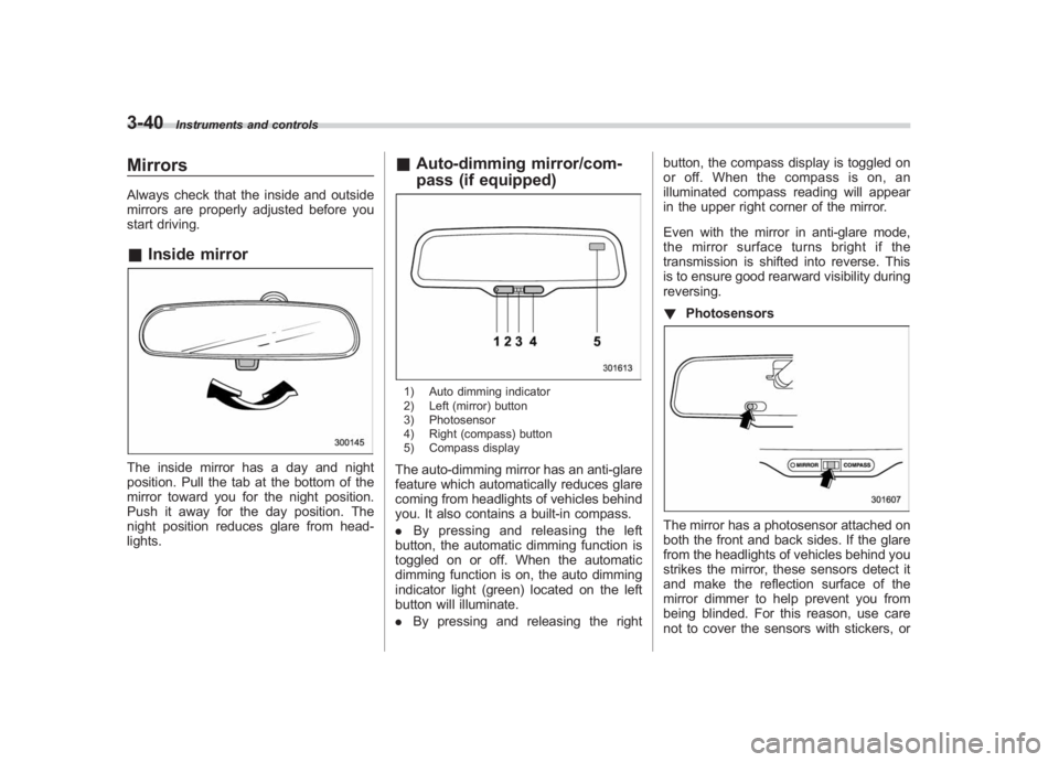
&Auto-dimming mirror/com-
pass (if equipped)1) Auto dimming indicator
2) Left (mirror) button
3) Photosensor
4) Right (compass) button
5) Compass displayThe auto-dimming mirror has an anti-glare
feature which automatically reduces glare
coming from headlights of vehicles behind
you. It also contains a built-in compass.
. By pressing and releasing the left
button, the automatic dimming function is
toggled on or off. When the automatic
dimming function is on, the auto dimming
indicator light (green) located on the left
button will illuminate.
. By pressing and releasing the right button, the compass display is toggled on
or off. When the compass is on, an
illuminated compass reading will appear
in the upper right corner of the mirror.
Even with the mirror in anti-glare mode,
the mirror surface turns bright if the
transmission is shifted into reverse. This
is to ensure good rearward visibility during
reversing.
!
Photosensors
The mirror has a photosensor attached on
both the front and back sides. If the glare
from the headlights of vehicles behind you
strikes the mirror, these sensors detect it
and make the reflection surface of the
mirror dimmer to help prevent you from
being blinded. For this reason, use care
not to cover the sensors with stickers, or
Page 161 of 459
Black plate (163,1)
北米Model "A1110BE-C" EDITED: 2010/ 12/ 17
other similar items. Periodically wipe the
sensors clean using a piece of dry soft
cotton cloth or an applicator.
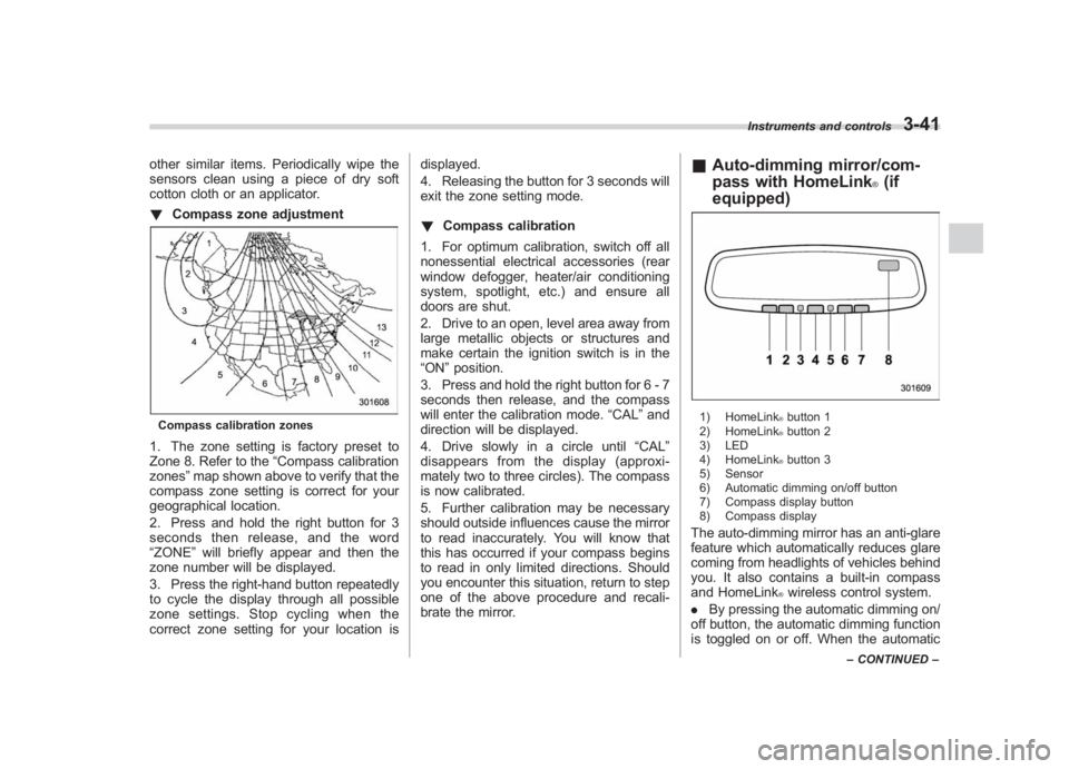
! Compass zone adjustmentCompass calibration zones1. The zone setting is factory preset to
Zone 8. Refer to the “Compass calibration
zones” map shown above to verify that the
compass zone setting is correct for your
geographical location.
2. Press and hold the right button for 3
seconds then release, and the word
“ZONE ”will briefly appear and then the
zone number will be displayed.
3. Press the right-hand button repeatedly
to cycle the display through all possible
zone settings. Stop cycling when the
correct zone setting for your location is displayed.
4. Releasing the button for 3 seconds will
exit the zone setting mode.
!
Compass calibration
1. For optimum calibration, switch off all
nonessential electrical accessories (rear
window defogger, heater/air conditioning
system, spotlight, etc.) and ensure all
doors are shut.
2. Drive to an open, level area away from
large metallic objects or structures and
make certain the ignition switch is in the
“ON ”position.
3. Press and hold the right button for 6 - 7
seconds then release, and the compass
will enter the calibration mode. “CAL”and
direction will be displayed.
4. Drive slowly in a circle until “CAL”
disappears from the display (approxi-
mately two to three circles). The compass
is now calibrated.
5. Further calibration may be necessary
should outside influences cause the mirror
to read inaccurately. You will know that
this has occurred if your compass begins
to read in only limited directions. Should
you encounter this situation, return to step
one of the above procedure and recali-
brate the mirror.
& Auto-dimming mirror/com-
pass with HomeLink
®(if
equipped)
1) HomeLink
®button 1
2) HomeLink®button 2
3) LED
4) HomeLink®button 3
5) Sensor
6) Automatic dimming on/off button
7) Compass display button
8) Compass display
The auto-dimming mirror has an anti-glare
feature which automatically reduces glare
coming from headlights of vehicles behind
you. It also contains a built-in compass
and HomeLink
®wireless control system.
. By pressing the automatic dimming on/
off button, the automatic dimming function
is toggled on or off. When the automatic
Instruments and controls
3-41
– CONTINUED –
3